Chrysler Le Baron, Dodge Dynasty, Plymouth Acclaim. Manual - part 43


  Index      Chrysler     Chrysler Le Baron, Dodge Dynasty, Plymouth Acclaim - service repair manual 1993 year


Search            


Content   ..  41  42  43  44   ..


Chrysler Le Baron, Dodge Dynasty, Plymouth Acclaim. Manual - part 43


resenting throttle blade position. As the position of
the throttle blade changes, the resistance of the TPS
changes.

The PCM supplies approximately 5 volts to the

TPS. The TPS output voltage (input signal to the
PCM) represents the throttle blade position. The TPS
output voltage to the PCM varies from approxi-
mately 0.5 volt at minimum throttle opening (idle) to
4 volts at wide open throttle. Along with inputs from
other sensors, the PCM uses the TPS input to deter-
mine current engine operating conditions and adjust
fuel injector pulse width and ignition timing.

VEHICLE SPEED SENSOR—PCM INPUT

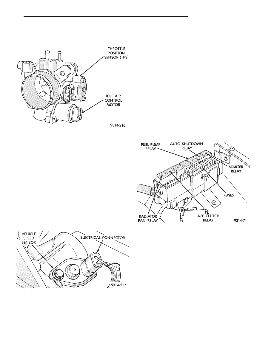
The vehicle speed sensor (Fig. 15) is located on the

transaxle extension housing. The sensor input is
used by the PCM to determine vehicle speed and dis-
tance traveled.

The speed sensor generates 8 pulses per sensor rev-

olution. These signals, along with a closed throttle
signal from the TPS, determine if a closed throttle
deceleration

or

normal

idle

condition

(vehicle

stopped) exists. Under deceleration conditions, the
PCM adjusts the idle air control motor to maintain a

desired MAP value. Under idle conditions, the PCM
adjusts the idle air control motor to maintain desired
engine speed.

AIR CONDITIONING CLUTCH RELAY—PCM
OUTPUT

The PCM operates the air conditioning clutch relay

ground circuit. The radiator fan relay supplies bat-
tery power to the solenoid side of the A/C clutch re-
lay. The air conditioning clutch relay will not
energize unless the radiator fan relay energizes. The
PCM energizes the radiator fan relay when the air
conditioning or defrost switch is put in the ON posi-
tion and the low pressure and high pressure switches
close. When the PCM senses wide open throttle
through the throttle position sensor, or low engine
RPM it will de-energize the A/C clutch relay, open
it’s contacts and prevent air conditioning clutch en-
gagement.

On AG Body vehicles, the relay is located in the

power distribution center (Fig. 16).

GENERATOR FIELD—PCM OUTPUT

The PCM regulates the charging system voltage

within a range of 12.9 to 15.0 volts. Refer to Group
8A for charging system information.

AUTO SHUTDOWN (ASD) RELAY AND FUEL PUMP
RELAY—PCM OUTPUT

The PCM operates the auto shutdown (ASD) relay

and fuel pump relay through one ground path. The
PCM operates the relays by switching the ground
path on and off. Both relays turn on and off at the
same time.

The ASD relay connects battery voltage to the fuel

injector and ignition coil. The fuel pump relay con-
nects battery voltage to the fuel pump and oxygen
sensor heating element.

The PCM turns the ground path off when the igni-

tion switch is in the Off position. Both relays are off.
When the ignition switch is in the On or Crank po-

Fig. 14 Throttle Position Sensor and Idle Air Control

Motor

Fig. 15 Vehicle Speed Sensor

Fig. 16 Power Distribution Center—AG Body

Ä

FUEL SYSTEMS

14 - 89

sition, the PCM monitors the crankshaft position and
camshaft position sensor signals to determine engine
speed and ignition timing (coil dwell). If the PCM
does not receive the crankshaft position sensor and
camshaft position sensor signals when the ignition
switch is in the Run position, it de-energizes both re-
lays. When the relays are de-energized, battery volt-
age is not supplied to the fuel injector, ignition coil,
fuel pump and oxygen sensor heating element.

The ASD relay and fuel pump relay are located in

the power distribution center (Fig. 16).

IDLE AIR CONTROL MOTOR—PCM OUTPUT

The idle air control motor is mounted on the throt-

tle body (Fig. 14). The PCM operates the motor. The
PCM adjusts engine idle speed through the idle air
control motor to compensate for engine load or ambi-
ent conditions.

The throttle body has an air bypass passage that

provides air for the engine at idle (the throttle blade
is closed). The idle air control motor pintle protrudes
into the air bypass passage and regulates air flow
through it.

The PCM adjusts engine idle speed by moving the

idle air control motor pintle in and out of the bypass
passage. The adjustments are based on inputs the
PCM receives. The inputs are from the throttle posi-
tion sensor, camshaft position sensor, crankshaft po-
sition

sensor,

coolant

temperature

sensor,

and

various switch operations (brake and air condition-
ing). Deceleration die out is also prevented by in-
creasing airflow when the throttle is closed quickly
after a driving (speed) condition.

BAROMETRIC READ SOLENOID—PCM OUTPUT

The barometric pressure read solenoid is spliced

into the manifold absolute pressure (MAP) sensor
vacuum hose (Fig. 12). The barometric read solenoid
switches the pressure supply to the MAP sensor from
either barometric pressure (atmospheric) or manifold
vacuum. The PCM operates the solenoid.

Atmospheric pressure is periodically supplied to

the MAP sensor to measure barometric pressure.
This occurs at closed throttle, once per throttle clo-
sure but no more often than once every 3 minutes
and within a specified RPM band. Barometric infor-
mation is used primarily for boost control and start
fuel enrichment at various altitudes.

CANISTER PURGE SOLENOID—PCM OUTPUT

Vacuum for the Evaporative Canister is controlled

by the Canister Purge Solenoid (Fig. 17). The sole-
noid is controlled by the PCM.

The PCM operates the solenoid by switching the

ground circuit on and off. When grounded, the sole-
noid energizes and prevents vacuum from reaching
the evaporative canister. When not energized the so-
lenoid allows vacuum to flow to the canister.

During warm-up and for a specified time period after

hot starts the PCM grounds the purge solenoid.
Vacuum does not operate the evaporative canister
valve.

The PCM removes the ground to the solenoid when

the engine reaches a specified temperature and the
time delay interval has occurred. When the solenoid is
de-energized, vacuum flows to the canister purge
valve. Vapors are purged from the canister and flow to
the throttle body.

The purge solenoid will also be energized during

certain idle conditions, in order to update the fuel
delivery calibration.

MALFUNCTION INDICATOR LAMP (CHECK
ENGINE)—PCM OUTPUT

The malfunction indicator lamp (instrument panel

Check Engine lamp) comes on each time the ignition
key is turned ON and stays on for 3 seconds as a bulb
test. The malfunction indicator lamp warns the opera-
tor that the PCM has entered a Limp-in mode. During
Limp-in-Mode, the PCM attempts to keep the system
operational. The malfunction indicator lamp signals
the need for immediate service. In limp-in mode, the
PCM compensates for the failure of certain components
that send incorrect signals. The PCM substitutes for
the incorrect signals with inputs from other sensors.

Signals that can trigger the malfunction indi-

cator lamp (Check Engine Lamp).
• Engine Coolant Temperature Sensor

• Manifold Absolute Pressure Sensor

• Throttle Position Sensor

• Battery Voltage Input

• An Emissions Related System

• Charging system

The malfunction indicator lamp can also be used to

display diagnostic trouble codes. Cycle the ignition
switch on, off, on, off, on, within five seconds and any

Fig. 17 EVAP Canister Purge Solenoid and Waste-

gate Control Solenoid

14 - 90

FUEL SYSTEMS

Ä

diagnostic trouble codes stored in the PCM will be
displayed. Refer to the 2.2L Turbo III Multi-port Fuel
Injection—On-Board

Diagnostics

section

of

this

Group for Diagnostic trouble code Descriptions.

DATA LINK CONNECTOR—PCM OUTPUT

The data link connector provides the technician

with the means to connect the DRBII scan tool to di-
agnosis the vehicle.

FUEL INJECTOR—PCM OUTPUT

The Fuel Injectors are electric solenoids driven by

the PCM (Fig. 18).

Based on sensor inputs, the PCM determines when

and how long the fuel injector should operate. The
amount of time an injector fires is referred to as in-
jector pulse width. The auto shutdown (ASD) relay
supplies battery voltage to the injector. The PCM
supplies the ground path. By switching the ground
path on and off, the PCM adjusts injector pulse
width.

When the PCM supplies a ground path, a spring

loaded needle or armature lifts from its seat and fuel
flows through the injector orifice.

Fuel is constantly supplied to the injector at regu-

lated 380 Kpa (55 psi). Unused fuel returns to the
fuel tank.

IGNITION COIL—PCM OUTPUT

The Direct Ignition System (DIS) uses a molded

coil (Fig. 19). The coil is mounted on the front of the
engine. High tension leads route to each cylinder
from the coil. The coil fires two spark plugs every
power stroke. One plug is the cylinder under com-
pression, the other cylinder fires on the exhaust
stroke. The PCM determines which of the coils to
charge and fire at the correct time.

The auto shutdown (ASD) relay provides battery

voltage to the ignition coil. The PCM provides a
ground contact (circuit) for energizing the coil. When

the PCM breaks the contact, the energy in the coil
primary transfers to the secondary causing the
spark. The PCM will de-energize the ASD relay if it
does not receive the crankshaft position sensor and
camshaft position sensor inputs. Refer to Auto Shut-
down (ASD) Relay/Fuel Pump Relay—PCM Output
in this section for relay operation.

RADIATOR FAN RELAY—PCM OUTPUT

The radiator fan is energized by the PCM through

the radiator fan relay. The PCM grounds the radia-
tor fan relay when engine coolant reaches a predeter-
mined temperature. For more information, refer to
Group 7, Cooling Systems.

The radiator fan relay is located in the power dis-

tribution center (Fig. 16). Refer to the Wiring and
Component Identification section of Group 8W.

SPEED CONTROL SOLENOIDS—PCM OUTPUT

The speed control vacuum and vent solenoids are

operated by the PCM. When the PCM supplies a
ground to the vacuum and vent solenoids, the speed
control system opens the throttle blade. When the
PCM supplies a ground only to the vent solenoid, the
throttle blade holds position. When the PCM removes
the ground from both the vacuum and vent solenoids,
the throttle blade closes. The PCM balances the two
solenoids to maintain the set speed. Refer to Group
8H for speed control information.

TACHOMETER—PCM OUTPUT

The PCM supplies engine RPM to the instrument

panel tachometer. Refer to Group 8 for tachometer
information.

WASTEGATE CONTROL SOLENOID—PCM OUTPUT

The PCM operates the wastegate control solenoid.

The PCM adjusts maximum boost to varying engine
conditions by changing the amount of time the sole-

Fig. 18 Fuel Injector

Fig. 19 Ignition Coil

Ä

FUEL SYSTEMS

14 - 91

noid is energized. The solenoid mounts to the passen-
ger side inner fender panel, next to the strut tower
(Fig. 17).

MODES OF OPERATION

As input signals to the PCM change, the PCM

adjusts its response to the output devices. For example,
the PCM must calculate a different injector pulse
width and ignition timing for idle than it does for wide
open throttle (WOT). There are several different modes
of operation that determine how the PCM responds to
the various input signals.

There are two different areas of operation, OPEN

LOOP and CLOSED LOOP.

During OPEN LOOP modes, the PCM receives input

signals and responds according to preset PCM pro-
gramming. Input from the oxygen (O

2

) sensor is not

monitored during OPEN LOOP modes.

During CLOSED LOOP modes, the PCM does moni-

tor the oxygen (O

2

) sensor input. This input indicates

to the PCM whether or not the calculated injector pulse
width results in the ideal air-fuel ratio of 14.7 parts air
to 1 part fuel. By monitoring the exhaust oxygen
content through the O

2

sensor, the PCM can fine tune

the injector pulse width to achieve optimum fuel
economy combined with low emissions.

The 2.2L Turbo III multi-port fuel injection system

has the following modes of operation:
• Ignition switch ON - Zero RPM

• Engine start-up

• Engine warm-up

• Cruise (Idle)

• Acceleration

• Deceleration

• Wide Open Throttle

• Ignition switch OFF

The engine start-up (crank), engine warm-up, and

wide open throttle modes are OPEN LOOP modes. The
acceleration, deceleration, and cruise modes, with the
engine at operating temperature 
are CLOSED
LOOP modes (under most operating conditions).

IGNITION SWITCH ON (ZERO RPM) MODE

When the ignition switch activates the fuel injection

system the following actions occur:
• The PCM calculates basic fuel strategy by determining
atmospheric air pressure from the MAP sensor input.
• The PCM monitors the coolant temperature sensor
and throttle position sensor input. The PCM modifies
fuel strategy based on this input.

When the key is in the ON position and the engine is

not running, the auto shutdown (ASD) relay and fuel
pump relay are not energized. Therefore battery volt-
age is not supplied to the fuel pump, ignition coil, fuel
injector or oxygen sensor heating element.

ENGINE START-UP MODE

This is an OPEN LOOP mode. The following actions

occur when the starter motor is engaged.

If the PCM receives the camshaft position and crank-

shaft position sensor signals, it energizes the auto
shutdown (ASD) relay and fuel pump relay. These
relays supply battery voltage to the fuel pump, fuel
injectors, ignition coil, and oxygen sensor heating ele-
ment. If the PCM does not receive the camshaft posi-
tion sensor and crankshaft position sensor signals
within approximately one second, it de-energizes the
ASD relay and fuel pump relay.

The PCM energizes all injectors until it determines

crankshaft position from the camshaft position sensor
and crankshaft position sensor signals. The PCM de-
termines crankshaft position within 1 engine revolu-
tion.

After determining crankshaft position, the PCM be-

gins energizing the injectors in sequence. The PCM
adjusts injector pulse width and controls injector syn-
chronization by turning the individual ground paths to
the injectors On and Off.

When the engine idles within

664 RPM of its target

RPM, the PCM compares current MAP sensor value
with the atmospheric pressure value received during
the Ignition Switch On (zero RPM) mode. If the PCM
does not detect a minimum difference between the two
values, it sets a MAP fault into memory.

Once the ASD and fuel pump relays have been

energized, the PCM:
• Determines injector pulse width based on coolant
temperature, manifold absolute pressure (MAP) and
the number of engine revolutions since cranking was
initiated.
• Monitors the coolant temperature sensor, camshaft
position sensor, crankshaft position sensor, MAP sen-
sor, and throttle position sensor to determine correct
ignition timing.

ENGINE WARM-UP MODE

This is a OPEN LOOP mode. The following inputs

are received by the PCM:
• engine coolant temperature

• knock sensor

• manifold absolute pressure (MAP)

• engine speed (crankshaft position sensor)

• throttle position

• A/C switch

• battery voltage

The PCM provides a ground path for the injectors to

precisely control injector pulse width (by switching the
ground on and off). The PCM adjusts engine idle speed
through the idle air control motor. Also, the PCM
regulates ignition timing.

14 - 92

FUEL SYSTEMS

Ä


Content   ..  41  42  43  44   ..