Chrysler Le Baron, Dodge Dynasty, Plymouth Acclaim. Manual - part 30
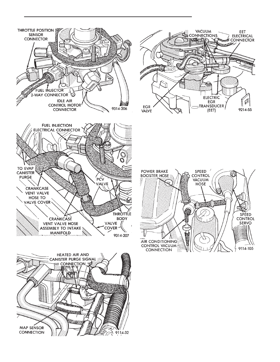
(16) Verify hoses are attached to back pressure
transducer or electric EGR transducer (EET) (Fig.
11).
(17) Verify heated air door vacuum connection is
connected and not leaking.
(18) Verify power brake and speed control vacuum
connectors are tight (Fig. 12).
(19) Verify all ignition cables are in correct order
and seated into place (Fig. 13).
(20) Verify the electrical connector is attached to
coolant temperature sensor (Fig. 14).
(21) Verify
battery
negative
ground
eyelet
is
mounted to the cylinder head (Figs. 14).
(22) Verify electrical connector is attached to dis-
tributor (Fig. 15).
(23) Verify radiator fan electrical connector is at-
tached to the harness (Fig. 15).
(24) Verify oil pressure switch electrical connector
is attached to the switch (Fig. 15).
Fig. 9 Vacuum Hose from Intake Manifold to PCV
Valve
Fig. 10 Throttle Body Vacuum Ports—Front
Fig. 8 Throttle Body Wiring Connections
Fig. 11 Throttle Body Vacuum Ports—Rear
Fig. 12 Power Brake and Speed Control Vacuum
Connection
Ä
FUEL SYSTEMS
14 - 37