Chrysler Le Baron, Dodge Dynasty, Plymouth Acclaim. Manual - part 10


  Index      Chrysler     Chrysler Le Baron, Dodge Dynasty, Plymouth Acclaim - service repair manual 1993 year


Search            


Content   ..  8  9  10  11   ..


Chrysler Le Baron, Dodge Dynasty, Plymouth Acclaim. Manual - part 10


EXHAUST SYSTEM AND INTAKE MANIFOLD

CONTENTS

page

page

GENERAL INFORMATION . . . . . . . . . . . . . . . . . . 1
SERVICE PROCEDURES

. . . . . . . . . . . . . . . . . . . 4

TORQUE SPECIFICATION

. . . . . . . . . . . . . . . . . 25

GENERAL INFORMATION

Throughout this group, references may be made to

a particular vehicle by letter or number designation.
A chart showing the breakdown of these designations
is included in the Introduction Section at the front of
this service manual.
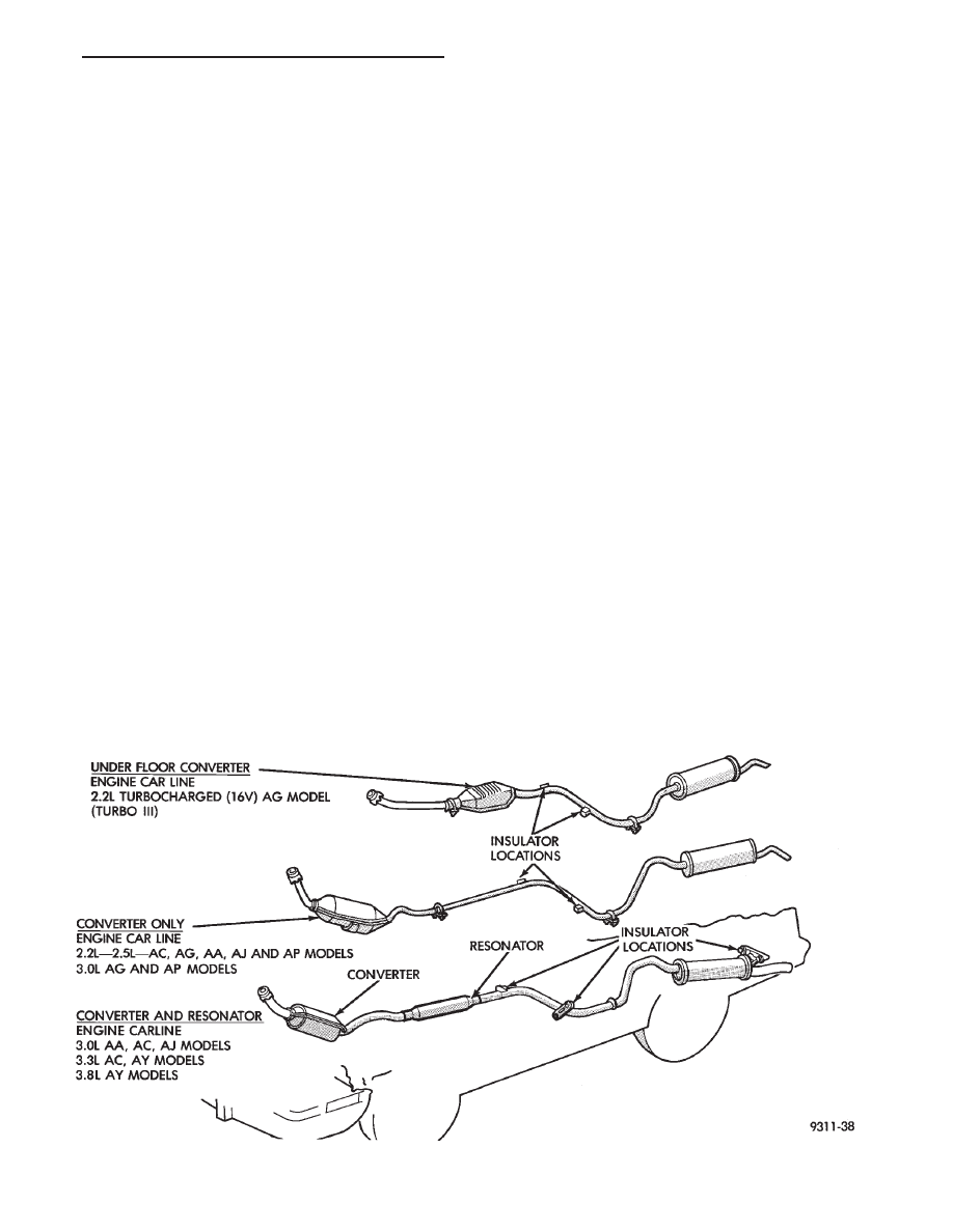
EXHAUST SYSTEMS

The exhaust systems are produced in several con-

figurations, depending on engine and car line (Fig.
1). One system has an underfloor catalytic converter,
other systems require front mounted catalytic con-
verters. The Turbo III engine requires, a underfloor
converter/resonator assembly. Tail pipes, mufflers,
and resonators are sized and tuned to each vehicle/
powertrain combination (Fig. 2).

EXHAUST BALL JOINT COUPLING

A exhaust ball joint coupling (Fig. 3) is used to se-

cure the exhaust pipe to the engine manifold. This
living joint actually moves back and forth as the en-

gine moves, preventing breakage that could occur
from the back-and-forth motion of a transverse
mounted engine.

The exhaust ball joint consists of two bolts, two

springs, and a ball joint seal ring which is a separate
part from the exhaust pipe.

CATALYTIC CONVERTER

There is no regularly scheduled maintenance on

any Chrysler catalytic converter. If damaged, the
converter must be replaced.

CAUTION: Due to exterior physical similarities of some
catalytic converters with pipe assemblies, extreme
care should be taken with replacement parts. There is
internal converter differences required in some parts
of the country (particularly California vehicles). 
The
2.2/2.5L engines equipped with a manual transmission will
have an adaptor for a air injection tube.

Fig. 1 Exhaust System

Ä

EXHAUST SYSTEM AND INTAKE MANIFOLD

11 - 1

HEAT SHIELDS

Heat shields (Fig. 4) are needed to protect both the

car and the environment from the high temperatures
developed in the vicinity of the catalytic converters.
2.2/2.5L engines equipped with manual transmission

where air is injected into the catalytic converter’s, a
heat shield is welded on the lower bottom of the front
converter.

Refer to Body and Sheet Metal, Group 23 for ser-

vice procedures.

Fig. 3 Ball Joint Connection

Fig. 4 Heat Shield Installation

Fig. 2 Exhaust System Components

11 - 2

EXHAUST SYSTEM AND INTAKE MANIFOLD

Ä

CAUTION: Avoid application of rust prevention
compounds or undercoating materials to exhaust
system floor pan heat shields on cars if equipped.
Light overspray near the edges is permitted. Appli-
cation of coating will greatly reduce the efficiency
of the heat shields resulting in excessive floor pan
temperatures and objectionable fumes.

The combustion reaction caused by the catalyst re-

leases additional heat in the exhaust system. Caus-
ing temperature increases in the area of the reactor
under severe operating conditions. Such conditions
can exist when the engine misfires or otherwise does
not operate at peak efficiency. Do not remove spark
plug wires from plugs or by any other means short
out cylinders if exhaust system is equipped with cat-
alytic converter. Failure of the catalytic converter
can occur due to temperature increases caused by un-
burned fuel passing through the converter.

The use of the catalysts also involves some non-au-

tomotive problems. Unleaded gasoline must be used
to avoid poisoning the catalyst core. Do not allow en-

gine to operate above 1200 RPM in neutral for ex-
tended periods over 5 minutes. This condition may
result in excessive exhaust system/floor pan temper-
atures because of no air movement under the vehicle.

EXHAUST GAS RECIRCULATION (EGR)
SYSTEM

To assist in the control of oxides of nitrogen (NOx)

in engine exhaust, some engines are equipped with
an exhaust gas recirculation system. The use of ex-
haust gas to dilute incoming air/fuel mixtures lowers
peak flame temperatures during combustion, thus
limiting the formation of NOx.

Exhaust gases are taken from openings in the ex-

haust gas crossover passage in the intake manifold.
REFER TO SECTION 25 EMISSION SYSTEMS
FOR A COMPLETE DESCRIPTION, DIAGNOSIS
AND SERVICE PROCEDURES ON THE EXHAUST
GAS RECIRCULATION SYSTEM AND COMPO-
NENTS.

EXHAUST SYSTEM DIAGNOSIS

Ä

EXHAUST SYSTEM AND INTAKE MANIFOLD

11 - 3

SERVICE PROCEDURES

INDEX

page

page

Exhaust Pipes, Mufflers and Tailpipes

. . . . . . . . . . 4

Intake and Exhaust Manifolds Service—TBI Engine

. 6

Intake and Exhaust Manifolds—Flexible Fuel Engine

. 7

Intake and Exhaust Manifolds—TBI Engine

. . . . . . 5

Intake/Exhaust Manifold Service—3.0L Engine

. . . 13

Intake/Exhaust Manifold Service—3.3/3.8L Engines

. 19

Intake/Exhaust Manifolds and Turbocharger

Service—Turbo III Engine

. . . . . . . . . . . . . . . . . . 9

Intake/Exhaust Manifolds Service—Flexible Fuel

Engines

. . . . . . . . . . . . . . . . . . . . . . . . . . . . . . . 7

EXHAUST PIPES, MUFFLERS AND TAILPIPES

REMOVAL

(1) Raise vehicle on hoist and apply penetrating oil

to clamp bolts and nuts of component being removed.

(2) Tail pipes are integral with the muffler (Fig. 5).

Remove clamp at slip joint. Separate at slip joint.

(3) Remove clamps and supports (Figs. 6, 7, 8, and 9)

from exhaust system to permit alignment of parts
during assembly.

(4) When removing tailpipe, raise rear of vehicle to

relieve body weight from rear springs to provide clear-
ance between pipe and rear axle parts.

(5) Clean ends of pipes and/or muffler to assure

mating of all parts. Discard broken or worn insulators,
rusted clamps, supports and attaching parts.

When replacement is required on any compo-

nent of the exhaust system, it is most important
that original equipment parts (or their equiva-
lent) be used;
• To insure proper alignment with other parts in the
system.
• Provide acceptable exhaust noise levels and does not
change exhaust system back pressure that could affect
emissions and performance.

INSTALLATION

(1) Assemble ball joint connection pipes, supports

and clamps loosely to permit alignment of all parts.

Fig. 6 Insulator Tail Pipe and Muffler Support

Fig. 7 Underfloor Converter or Extension Pipe

Support—2 Places

Fig. 5 Tail Pipe with Muffler—Typical

11 - 4

EXHAUST SYSTEM AND INTAKE MANIFOLD

Ä


Content   ..  8  9  10  11   ..