Chery B14. Manual - part 6
S
ervice Manual for Chery V525 Car Chassis
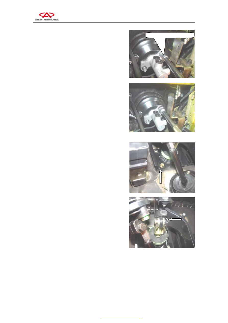
4.2.2 Remove two stay bolts that secure vacuum booster
via 13# sleeve.
Note: there are two nuts behind the brake pedal in the
driver's cabin connect with these stay bolts.
Torque: 25±2.5Nm
4.2.3 Loosen the two nuts securing brake master
cylinder and vacuum booster via 22# sleeve, and then
take out brake master cylinder.
4.3 Disassembly of vacuum booster
4.3.1 Loosen the two fixing bolts of vacuum booster
behind the brake pedal inside the driver's cabin via 13#
sleeve.
Torque: 25±2.5N.m
4.3.2 Remove the circlip of vacuum booster and brake
pedal joint pin via pincers, and then take out the pin.
Loosen the clamp clip, and then pull out the vacuum
tube of vacuum booster and intake pipe. Take out the
vacuum booster from front compartment. If the vacuum
booster assembly is out of service, please replace
accordingly.
4.4 Assembly procedures
Assembly sequence is reverse to that of disassembly.
4.5 Ventilation of brake system
4.5.1 After disassembly and assembly of brake system, it is
required to carry out system ventilation to ensure satisfactory
braking effect.