Bobcat S150. Manual - part 17
S150 Bobcat Loader
53
Operation & Maintenance Manual
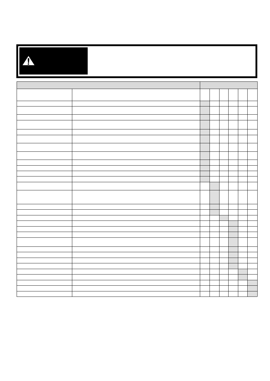
SERVICE SCHEDULE
Chart
Maintenance work must be done at regular intervals. Failure to do so will result in excessive wear and early failures. The
service schedule is a guide for correct maintenance of the Bobcat loader.
WARNING
Instructions are necessary before operating or servicing machine. Read
and understand the Operation & Maintenance Manual, Handbook and signs
(decals) on machine. Follow warnings and instructions in the manuals
when making repairs, adjustments or servicing. Check for correct function
after adjustments, repairs or service. Untrained operators and failure to
follow instructions can cause injury or death.
W-2003-0903
SERVICE SCHEDULE
HOURS
ITEM
SERVICE REQUIRED
8-10
50
100
■
250
■
500
■
1000
Engine Oil
Check the oil level and add as needed.
Engine Air Filter and Air System
Check display panel. Service only when required. Check for leaks and
damaged components.
Engine Cooling System
Clean debris from oil cooler, radiator & grill.
Lift Arms, Cylinders, Bob-Tach
Pivot Pins and Wedges
Lubricate with multi-purpose lithium based grease.
Tires
Check for damaged tires and correct air pressure.
Seat Belt, Seat Bar, Control
Interlocks
Check the condition of seat belt. Check the sear bar and control interlocks for
correct operation. Clean dirt and debris from moving parts.
Bobcat Interlock Control Systems
(BICS™)
Check that four (4) BICS™ indicator lights and functions are activated. See
details in this Manual.
Safety Signs and Safety Treads
Check for damaged signs (decals) and safety treads. Replace any signs or
safety treads that are damaged or worn.
Operator Cab
Check the fastening bolts, washers and nuts. Check the condition of the cab.
Indicators and Lights
Check for correct operation of all indicators and lights.
Fuel Filter
Remove the trapped water.
Heater Filters
Clean or replace filters as needed during heating season.
Hydraulic Fluid, Hoses and
Tubelines
Check fluid level and add as needed. Check for damage and leaks. Repair or
replace as needed.
Final Drive Trans. (Chaincase),
Foot Pedals, Hand Controls or
Steering Levers
Check oil level. Check for correct operation. Repair or adjust as needed.
Wheel Nuts
Check for loose wheel nuts and tighten to 142-156 Nm torque.
❏
Parking Brake
Check operation.
Battery
Check cables, connections and electrolyte level. Add distilled water as needed.
Engine/Hydro. Drive Belt
Check for wear or damage. Check idler arm stop.
*
Alternator Belt
Check tension and adjust as needed.
Air Condition Belt
Check belt for wear. Adjust or replace as needed.
Bobcat Interlock Control System
(BICS™)
Check the function of the lift arm by-pass control.
Fuel Filter
Replace filter element.
Steering Shaft
Grease fittings.
Fan Drive Gearbox
Check gear lube level.
Engine Oil and Filter
Replace oil and filter. Use CD or better grade oil and Bobcat filter.
^
Hydraulic Reservoir Breather Cap Replace the reservoir breather cap.
Hyd./Hydro. Filter
●
Replace the filter element.
Final Drive Trans. (Chaincase)
Replace the fluid.
Hydraulic Reservoir
Replace the fluid.
Case Drain Filters
Replace the filters.
❏
Check wheel nut torque every 8 hours for the first 24 hours.
*
Inspect the new belt after first 50 hours.
●
Also replace hydraulic/hydrostatic filter element when the transmission warning light comes ON.
^ First oil and filter change must occur at 50 hours; 500 hours thereafter.
■
Or every 12 months.