Bobcat S150. Manual - part 18


  Index      Bobcat     Bobcat S150 Skid Steer Loader - service manual 2005 year


Search            


Content   ..  16  17  18  19   ..


Bobcat S150. Manual - part 18


S150 Bobcat Loader

57

Operation & Maintenance Manual

OPERATOR CAB (CONT’D)

Lowering The Operator Cab

Always stop the engine before raising or lowering the cab.

NOTE: Make sure the seat bar is fully raised or

lowered when lowering the cab. Always use
the grab handles to lower the cab.
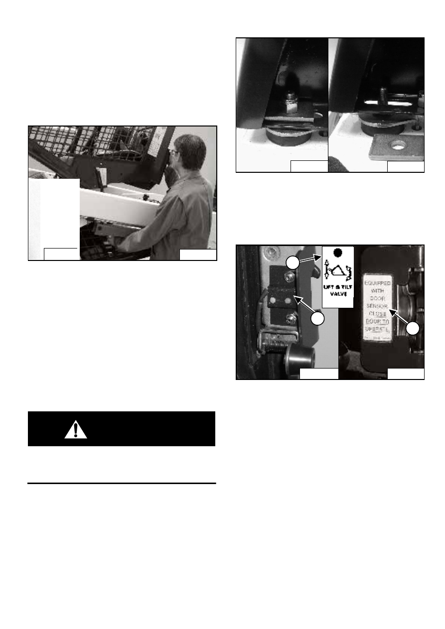
Figure 109

Pull down on the bottom of the operator cab until it stops
at the latching mechanism [Figure 109].

NOTE: The weight of the cab increases when

equipped with options and accessories such
cab door, heater, air conditioning, etc. In
these cases, the cab may need to be raised
slightly from the latch to be able to release the
latch.

Support the cab and release the latching mechanism
(Inset)  [Figure 109]. Remove your hand from latching
mechanism when the cab is past the latch stop. Use both
hands to lower the cab all the way.

WARNING

PINCH POINT CAN CAUSE INJURY

Remove your hand from the latching mechanism
when the cab is past the latch stop.

W-2458-0103

Figure 110

Install the plates and nuts (both sides) [Figure 110].

Tighten the nuts to 54-68 Nm torque.

Cab Door Sensor

Figure 111

The cab door (option) has a sensor (1[Figure 111]
installed which deactivates the lift and tilt valves when the
door is open.

A decal is located on the latch mechanism (2)
[Figure 111].

The LIFT & TILT VALVE light (3) [Figure 111] will be ON
when the door is closed and the PRESS TO OPERATE
LOADER Button is pressed.

P-45262

N-20120

P-31289

P-31288

P-34171

1

P-31202

3

2

B-15551j

S150 Bobcat Loader
Operation & Maintenance Manual

58

OPERATOR CAB (CONT’D)

Emergency Exit

The front opening on the operator cab and rear window
provide exits.

Rear Window (If Equipped)

Figure 112

Pull on the tag [Figure 112] on the top of the rear window
to remove the rubber cord.

Push the rear window out of the rear of the operator cab.

Figure 113

Exit through the rear of the operator cab [Figure 113].

WARNING

Never modify operator cab by welding, grinding,
drilling holes or adding attachments unless
instructed to do so by Bobcat. Changes to the cab
can cause loss of operator protection from rollover
and falling objects, and result in injury or death.

W-2069-1299

Front Door (If Equipped)

Figure 114

NOTE: When an Operator Cab Enclosure Kit is

installed, the window of the front door can be
used as an emergency exit [Figure 115].

Pull the plastic loop at the top of the window in the front
door to remove the rubber cord (1) [Figure 114].

Figure 115

Push the window out with your foot [Figure 115] at any
corner (X) of the window.

Exit through the front door.

N-19386

P-45260

N-20171

1

P-30254

X

X

X

X

6707852

S150 Bobcat Loader

59

Operation & Maintenance Manual

SEAT BELT

Inspection and Maintenance

WARNING

Failure to properly inspect and maintain the seat belt
can cause lack of operator restraint resulting in
serious injury or death.

W-2466-0703

Check the seat belt daily for correct function.

Inspect the seat belt system thoroughly yearly or more
often if the machine is exposed to severe environmental
conditions or applications.

The seat belt system should be repaired or replaced if it
shows cuts, fraying, extreme or unusual wear, significant
discolorations due to ultraviolet (UV) rays from the sun,
dusty/dirty conditions, abrasion to the seat belt webbing,
or damage to the buckle, latch plate, retractor
(if equipped), hardware.

The items below are referenced in [Figure 116].

1.

Check the webbing. If the system is equipped with a
retractor, pull the webbing completely out and inspect
the full length of the webbing. Look for cuts, wear,
fraying, dirt and stiffness.

2.

Check the buckle and latch for proper function. Make
sure latch plate is not excessively worn, deformed or
buckle is not damaged.

3.

Check the retractor web storage device (if equipped)
by extending the seat belt webbing to determine if it
extends and retracts the webbing correctly.

4.

Check webbing in areas exposed to ultraviolet (UV)
rays from the sun or extreme dust or dirt. If the original
color of the webbing in these areas is extremely faded
and/or the webbing is packed with dirt, the webbing
strength may have weakened.

See your Bobcat dealer for approved seat belt system
replacement parts for your machine.

Figure 116

B-22283

S150 Bobcat Loader
Operation & Maintenance Manual

60

SEAT BAR RESTRAINT SYSTEM

The seat bar restraint system has a pivoting seat bar with
arm rests.

The operator controls the use of the seat bar. The seat
bar in the down position helps to keep the operator in the
seat.

Models with foot pedals have hydraulic valve spool
interlocks for the lift and tilt functions. The spool
interlocks require the operator to lower the seat bar in
order to operate the foot pedal controls.

When the seat bar is down, the PRESS TO OPERATE
LOADER Button is activated and the engine is running,
the lift, tilt and traction drive functions can be operated.

When the seat bar is up, the lift and tilt control pedals are
locked when returned to the NEUTRAL position.

Models with the Advanced Control System (ACS)
have mechanical interlocks for the handles and pedals.
The interlocks for the handles and pedals require the
operator to lower the seat bar in order to operate the
controls.

When the seat bar is down, the PRESS TO OPERATE
LOADER button is activated and the engine is running,
the lift, tilt and traction drive functions can be operated.

When the seat bar is up, the handles and pedals are
locked when returned to the NEUTRAL position.

Models with Selectable Joystick Control (SJC) have
electrical deactivation of joystick functions. Activation of
functions require the operator to lower the seat bar.

When the seat bar is down, the PRESS TO OPERATE
LOADER button is activated and the engine is running,
the lift, tilt and traction drive functions can be operated.

When the seat bar is up, the joystick functions are
deactivated even though the joystick does not
mechanically lock.

Inspecting The Seat Bar

Sit in the seat and fasten the seat belt. Engage the
parking brake. Pull the seat bar all the way down. Start
the engine. Press the PRESS TO OPERATE LOADER
Button.

Operate the hydraulic controls to check that both the lift
and tilt functions operate correctly. Raise the lift arms
until the attachment is about 600 mm off the ground.

Raise the seat bar. Move the hydraulic controls. Pedals
and handles (if equipped) must be firmly locked in the
NEUTRAL position. There must be no motion of the lift
arms or tilt (attachment) when the controls are moved.

Lower the seat bar, press the PRESS TO OPERATE
LOADER Button, lower the lift arms. Operate the lift
control. While the lift arms are going up, raise the seat
bar. The lift arms must stop.

Lower the seat bar, press the PRESS TO OPERATE
LOADER Button, lower the lift arms and put the
attachment flat on the ground. Stop the engine. Raise the
seat bar. Operate the foot pedals and handles (if
equipped) to be sure that the pedals are firmly locked in
the NEUTRAL position. Unfasten the seat belt.

Maintaining The Seat Bar

Check the SERVICE SCHEDULE Decal on the loader for
correct service interval. (See SERVICE SCHEDULE on
Page 53.)

Figure 117

Use compressed air to clean any debris or dirt from the
pivot parts (1[Figure 117]. Do not lubricate. Inspect all
mounting hardware. The correct bolt torque is 35 Nm.

If the seat bar system does not function correctly, replace
parts that are worn or damaged. Use only genuine
Bobcat replacement parts.

WARNING

The seat bar system must deactivate the lift and tilt
control functions when the seat bar is up. Service the
system if hydraulic controls do not deactivate.

W-2465-0703

N-19225

1


Content   ..  16  17  18  19   ..