Loader Bobcat 773. Manual - part 77


  Index      Bobcat     Bobcat 773 - service manual 1997 year


Search            


Content   ..  75  76  77  78   ..


Loader Bobcat 773. Manual - part 77


STARTER (DENSO) (Cont’d)

Disassembly (Cont’d)

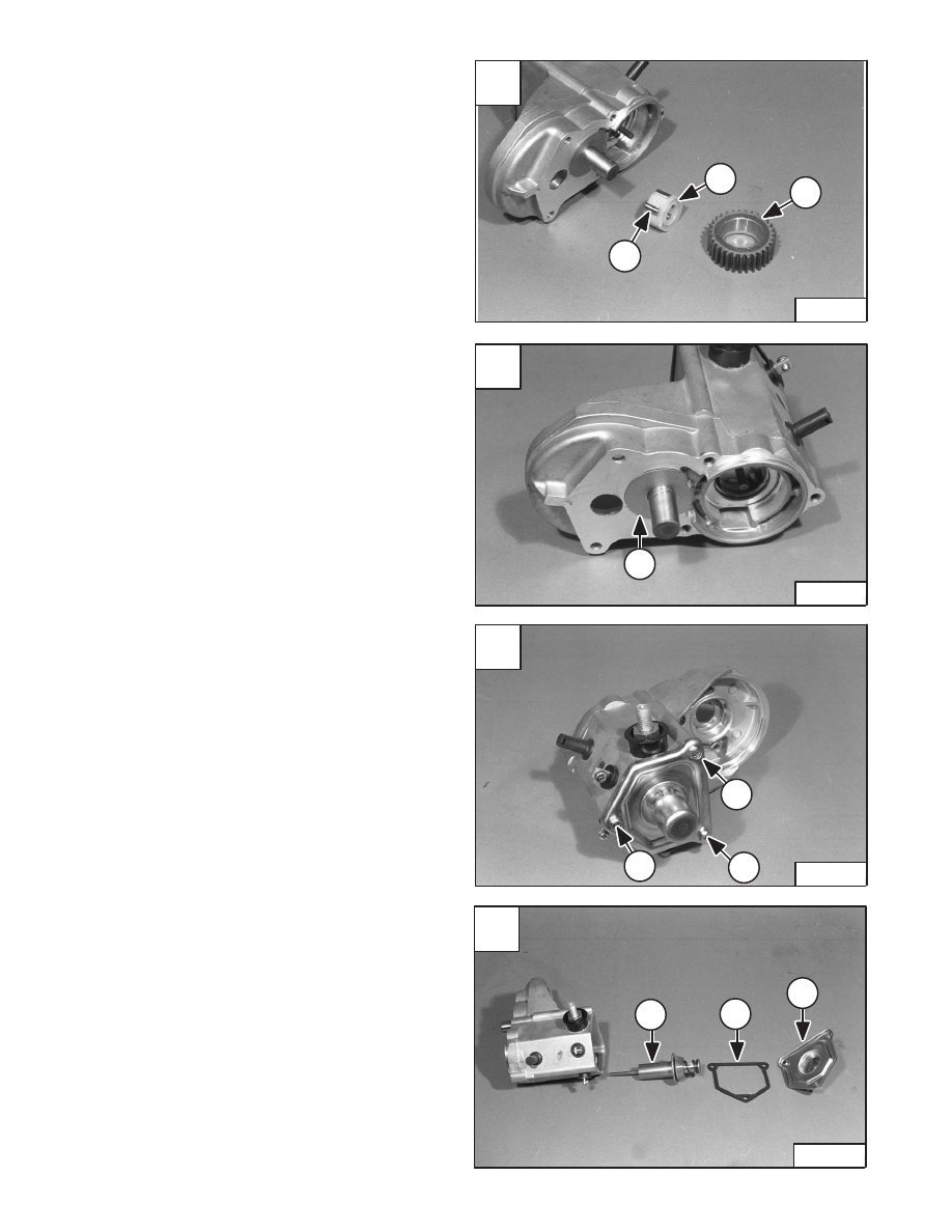
Remove the idler gear (Item 1) [A], retainer (Item 2) [A]
and rollers (Item 3) [A] from the magnetic switch housing.

Remove the washer (Item 1) [B] from the idler gear shaft.

Remove the bolts (Item 1) [C] from the magnetic switch.

Remove the cover (Item 1) [D], gasket (Item 2) [D] and
switch (Item 3) [D].

A

N–15168

2

3

1

C

N–15150

1

1

1

D

N–15151

3

2

1

–6–24–

773 BICS Loader

Service Manual

B

N–15169

1

STARTER (DENSO) (Cont’d)

Inspection And Repair

Inspect the brush cover for discoloration, indication the
starter has been overheated.

Inspect the pinion teeth for wear and damage.

Armature Short–Circuit Test: Use a growler tester, put the
armature on the growler and hold a hack saw blade
against the armature core while slowly rotating the
armature [A]. A short circuited armature causes the blade
to vibrate and be attracted to the core. An armature which
is short–circuited must be replaced.

Armature Winding Ground Test: Use a circuit tester, touch
one probe to a commutator segment and the other probe
to the armature core [B]. There should be no continuity.
If there is continuity, the armature is grounded and must
be replaced.

Armature Winding Continuity Test: Use a circuit tester,
touch the probes to two commutator segments [C]. There
should be continuity at any point. If there is no continuity,
the winding is open–circuited, replace the armature.

Commutator Run–Out Test: check the commutator
run–out as shown in [D].

Service Limit – 0.020 inch (0,4 mm)

If the commutator exceeds the service limit, repair as
needed.

A

B–14455

C

N–00997

D

B–14458

773 BICS Loader

–6–25–

Service Manual

773 Service Manual #6900092–Electrical System Section Part 1 of 2

B

N–00996

STARTER (DENSO) (Cont’d)

Inspection And Repair (Cont’d)

Measure the segment mica depth (Item 1) [A].

Service Limit – 0.008 inch (0,2 mm)

If it is worn, replace the armature.

Check the commutator surface for burned spots which
usually indicates an open–circuit, and correct it using
#400 sand paper.

Check the field windings for wear and damage.

Check all the connections for clean and tight solder joints.

Field Winding Ground Test: Use a circuit tester, touch one
probe to the field winding end of the brush and the other
probe to the surface of the frame [B]. There should be no
continuity. If there is continuity, the field windings are
grounded.

Replace the frame.

Field Windings Continuity Test: Use a circuit tester, touch
one probe to the wire and the other probe to the brush [C].
There should be continuity. If there is no continuity, the
field windings are open–circuited.

Replace the frame.

Inspect the brushes for wear and damage.

Replace the brush holder and yoke if the brushes need
replacement.

Check brush spring, for damage or rust. Replace as
needed.

Brush Holder Insulation Test: Use a circuit tester, touch
one probe to the positive brush holder plate and the other
probe to the holder plate [D]. There should be no
continuity. If there is continuity, replace or repair.

A

B–14460

1

C

N–15005

D

N–15006

–6–26–

773 BICS Loader

Service Manual

B

N–00999

STARTER (DENSO) (Cont’d)

Inspection and Repair (Cont’d)

NOTE: Assemble the over running clutch, pinion

shaft, springs, and pinion for this test.

Inspect the pinion, it must rotate freely in the direction of
the starter rotation and locked in the opposite rotation.

Pull the pinion out (to the engaged position) [A] and allow
it to snap back to the retracted position. The pinion must
fully return to the retracted position.

The following tests should be done without the armature
assembly. Install the magnetic switch in the switch
housing.

NOTE: Each test should be performed a short time

(3 to 5 seconds) to prevent the magnetic
switch winding from burning. Each test
should be performed with 12 volts.

Pull–In Test: Connect the wires as shown in [B]. When
connecting Terminal C and M.T. are closed, the pinion
should engage.

Hold–In Test: With the same conditions as in the pull–in
test, open the connecting Terminal C [C]. The pinion
should remain in the engaged position.

Return Test: With the same conditions as in the hold–in
test, open the connecting Terminal 50 [D]. The pinion
should return immediately.

M.T.

Main Terminal to which the main cable from the

. . . 

battery is connected.

C

C–Terminal to  which  the wire  from  the  field

. . . . . . 

windings is connected.

50

50–Terminal to which the wire from the starting

. . . . . 

switch or stator relay is connected.

A

N–15012

C

B–14470

C

50

M.T.

D

B–14469

C

50

M.T.

773 BICS Loader

–6–27–

Service Manual

B

B–14471

C

50

M.T.


Content   ..  75  76  77  78   ..