Volvo V70 (2016 year). Instruction - part 22
||
10 Maintenance and service
10
376
1. Insert the remote control key in the igni-
tion switch
11
and briefly press the
START/STOP ENGINE button to set the
car's electrical system to key position I.
For detailed information on key positions,
see Key positions - functions at different
2. Briefly press the START/STOP ENGINE
button again to set the car’s electrical
system in key position 0.
3. Within 3 seconds, move the right stalk
switch up and hold it in position for
approx. 1 second.
> The wipers then move to standing
straight up.
The wipers return to their starting position
when you briefly press the START/STOP
ENGINE button to set the car’s electrical sys-
tem to key position I (or when the car is
started).
If the wiper arms in service position have
been folded up from the windscreen, they
must be folded back down onto the wind-
screen before the wipers are allowed to
return to their starting position. This is to
avoid scraping the paint on the bonnet.
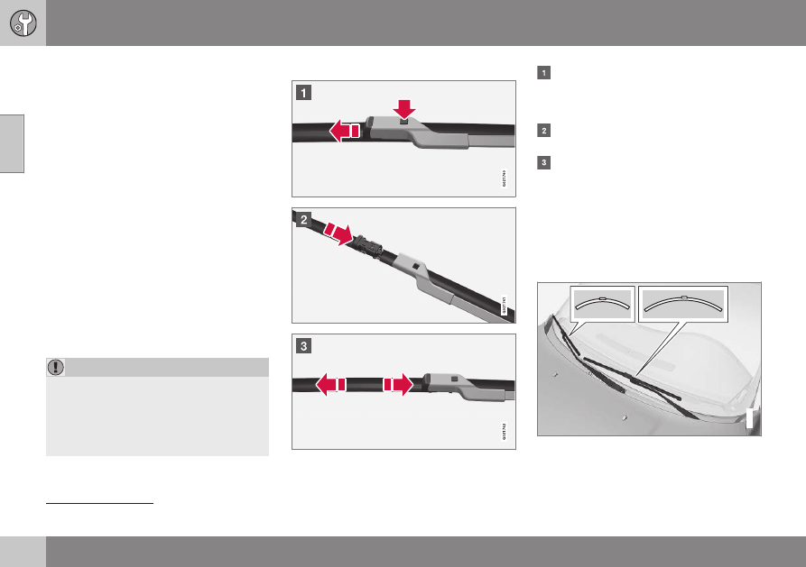
Replacing the wiper blades
Fold up the wiper arm when it is in serv-
ice position. Press the button located on
the wiper blade mounting and pull
straight out parallel with the wiper arm.
Slide in the new wiper blade until a "click"
is heard.
Check that the blade is firmly installed.
4. Fold the wiper arm back towards the
windscreen.
The wipers return from service position to
their starting position when you briefly press
the START/STOP ENGINE button to set the
car’s electrical system to key position I (or
when the car is started).
G021763
11
Not necessary in cars with the Keyless function.