Volvo V70 (2016 year). Instruction - part 21
10 Maintenance and service
10
360
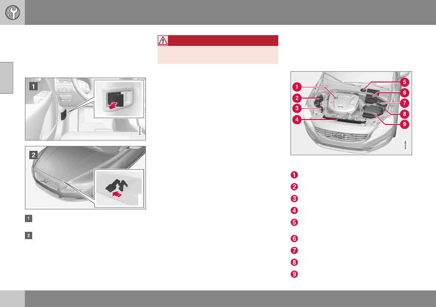
Bonnet - opening and closing
The bonnet can be opened when the handle
by the pedals has been pulled backward and
the lock by the radiator grille has been moved
to the left.
G010951
Pull the handle by the pedals. You will
hear when the catch releases.
Move the catch to the left and open the
bonnet. (The catch hook is located
between the headlamp and radiator grille,
see illustration.)
WARNING
Check that the bonnet locks properly when
closed.
Related information
•
Engine compartment - checking (p. 361)
•
Engine compartment - overview (p. 360)
Engine compartment - overview
The overview shows some service-related
components.
Engine compartment 4-cyl.
The appearance of the engine compartment may
differ depending on engine variant.
Filling engine oil
Coolant expansion tank
Power steering fluid reservoir
Radiator
Reservoir for brake and clutch fluid
(located on the driver's side)
Starter battery
Relay and fuse box
Filling washer fluid
Air filter