Volvo XC70 (2016 year). Instruction - part 5


  Index      Volvo     Volvo XC70 - instruction 2016 year in english


Search            


Content   ..  3  4  5  6   ..


Volvo XC70 (2016 year). Instruction - part 5


03 Instruments and controls

03

*


Option/accessory, for more information, see Introduction.

77

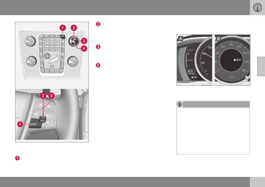
The center console control panel and the steer-

ing wheel keypad. The illustration is generic and

the appearance/location of the buttons may vary.

MY CAR: opens the MY CAR menu sys-

tem.

OK/MENU: Press the button on the cen-

ter console or the thumb wheel on the

steering wheel keypad to select a menu

alternative or to store a selected function

in the system's memory.
TUNE: Turn this control on the center

console or the thumb wheel on the steer-

ing wheel keypad to navigate up/down in

a menu.
EXIT

EXIT functions
Depending on which function the cursor is

pointing to and the menu level, briefly press-

ing EXIT will result in:

An in-coming phone call will be rejected

The current function will be cancelled

Characters entered will be erased

The most recent selection will be cancel-

led

Go back/up in the menu system

Pressing and holding EXIT takes you to the

normal view for MY CAR. If you are already in

normal view, this will take you to the main

source menu.

Menu selections and paths
Please consult your Sensus Infotainment sup-

plement for a description of the MY CAR

menu selections and paths.

Information displays – ambient

temperature sensor

Location of the ambient temperature sensor, A:

digital instrument panel*, B: analog instrument

panel

NOTE

When the ambient temperature is between

23° and 36 °F (–5° and +2 °C), a snowflake

symbol will be displayed next to the tem-

perature. This symbol serves as a warning

for possible slippery road surfaces. Please

note that this symbol does not indicate a

fault with your vehicle.
At low speeds or when the vehicle is not

moving, the temperature readings may be

slightly higher than the actual ambient

temperature.

Related information

Information displays – introduction (p. 68)

03 Instruments and controls

03

78

*


Option/accessory, for more information, see Introduction.

Information displays – trip odometer

and clock

The trip odometers 

T1

 and 

T2

 and clock are

displayed in the instrument panel.

Trip odometers

Trip odometer

4

Odometer display

Turn the thumb wheel on the left steering

wheel lever to display the desired trip odome-

ter.
Press and hold the RESET button on the left

steering wheel lever for at least 1 second to
reset the selected trip odometer

5

.

Clock

Clock, digital instrument panel*

Display

6

Setting the clock

The clock can be set in the MY CAR menu

system. See My Car – introduction (p. 76) for

additional information about these menus.

Go to 

Settings

System options

Time

settings

. Set 

Auto time

 to ON (check the

box) and select the correct time zone under

Location

.

Related information

Information displays – introduction (p. 68)

Inserting/removing remote key

The remote key is used to start the engine or

to use various electrical functions without

starting the engine.

Inserting and removing the remote key

Ignition slot with remote key and START/STOP

ENGINE button.

Inserting the remote key

7

Holding the end of the remote key with the

base of the key blade, insert the remote key

into the ignition slot as shown in the illustra-

tion and press it in as far as possible.

CAUTION

Foreign objects in the ignition slot can

impair function or cause damage.

4

The trip odometer will be displayed differently in analog and digital instrument panels

5

Models with a digital information panel: press and hold RESET for more than approximately 4 seconds to reset all trip computer information

6

Models with an analog instrument panel: the time will be displayed in the center of the instrument panel

7

Not necessary in vehicles with the optional keyless drive.

03 Instruments and controls

03

}}

*


Option/accessory, for more information, see Introduction.

79

Removing the remote key
The remote key can be removed from the

ignition slot by pulling it out.

Related information

Ignition modes (p. 79)

Ignition modes

The vehicle's ignition has 3 modes: 0I, and II

that can be used without starting the engine.

The following table shows examples of which

functions are available in the respective

modes.

NOTE

To access ignition modes I or II without

starting the engine, the brake pedal must

not be depressed.

Mode Function

0

The odometer, clock and tem-

perature gauge are illuminated.

Power seats* can be adjusted

and the infotainment system can

be used for a limited time (to min-

imize battery drain, see the Sen-

sus Infotainment Supplement).

I

The Moonroof*, power windows,

12-volt sockets in the passenger

compartment, navigation sys-

tem*, climate system blower,

windshield wipers can be used.

II

The headlights/taillights illumi-

nate. Warning/indicator lights illu-

minate for 5 seconds. Other sys-

tems are activated. However, the

heated seats* and heated rear

window function can only be acti-

vated when the engine is running.

Mode II should only be used for

very short periods to help avoid

draining the battery.

Ignition modes

Ignition mode 0

The vehicle is unlocked.

||

03 Instruments and controls

03

80

*


Option/accessory, for more information, see Introduction.

Ignition mode I

With the remote key fully pressed into the
ignition slot

8

, press START/STOP

ENGINE briefly.

Ignition mode II

With the remote key fully pressed into the
ignition slot

8

, press START/STOP

ENGINE for approximately 2 seconds.

Returning to mode 0

To return to mode 0 from mode II or I, press

START/STOP ENGINE briefly.

Starting and stopping the engine
See Starting the engine (p. 246) and Switch-

ing off the engine (p. 248) for information on

starting the engine and switching it off.

Emergency towing
See Towing the vehicle (p. 284) for important

information about the remote key when the

vehicle is being towed.

Related information

Inserting/removing remote key (p. 78)

Front seats

The front seats can be adjusted in a number

of ways to help provide the most comfortable

seating position.

Raise/lower the seat, pump up/down.

Front-rear adjustment: lift the bar and

move the seat to the position of your

choice.
Raise/lower front edge of seat cushion,

pump up/down.
Backrest tilt: turn the control to adjust the

angle of the backrest.
Electronic lumbar support*. Press the

button to adjust.
Control panel for power seat*, see Front

seats – power seat (p. 81).

WARNING

Do not adjust the seat while driving.

The seat should be adjusted so that

the brake pedal can be depressed

fully. In addition, position the seat as

far rearward as comfort and control

allow.

Check that the seat is securely locked

into position after adjusting.

Related information

Front seats – power seat (p. 81)

Rear seats – folding backrest (p. 86)

Rear seats – head restraints (p. 84)

8

Not necessary in vehicles with the optional keyless drive.

03 Instruments and controls

03

}}

*


Option/accessory, for more information, see Introduction.

81

Front seats – folding backrest*

The front passenger's seat backrest can be

folded down to make it easier to transport

long objects.

The front passenger seat backrest can be

folded to a horizontal position to make room

for a long load. Fold the backrest as follows:

Move the seat as far back and down as

possible.
Adjust the backrest to an upright position.

Lift the catches on the rear of the back-

rest.
Without releasing the catches, push the

backrest forward.
Move the seat as far forward as possible

so that the head restraint slides under the

glove compartment.

Return the seat to its upright position in the

reverse order.

WARNING

When transporting long objects, cover

sharp edges on the load to help pre-

vent injury to occupants. Secure the

load to help prevent shifting during

sudden stops.

When the seat's backrest is returned

to the upright position, push and pull it

to be sure that it is securely locked in

this position.

Related information

Front seats (p. 80)

Front seats – power seat (p. 81)

Rear seats – folding backrest (p. 86)

Rear seats – head restraints (p. 84)

Front seats – power seat

11

The power seat(s) can be adjusted for a short

period after unlocking the door with the

remote control without the key in the ignition

slot. Seat adjustment is normally made when

the ignition is on and can always be made

when the engine is running.

Power seat

Power seat adjustment controls

Front edge of seat cushion up/down

Raise/lower the seat

Seat forward/rearward

Backrest tilt

Electronic lumbar support*

||

03 Instruments and controls

03

82

*


Option/accessory, for more information, see Introduction.

Operation

NOTE

Only one of the power seat's controls

can be used at the same time.

The power seats have an overload

protector that activates if a seat is

blocked by any object. If this occurs,

switch off the ignition (key in posi-

tion 0) and wait for a short period

before operating the seat again.

Power seat memory function

Power seat memory buttons

Button for storing a position

Button for storing a position

Button for storing a position

M (memory) button

Programming the seat's memory

Three different seating and door mirror posi-

tions can be stored in the driver seat's mem-

ory.
The following example explains how button

(1) can be programmed. Buttons (2) and (3)

are programmed in the same way.
To program (store) a seat and door mirror

position in button (1):
1. Move the seat (and door mirrors) to the

desired positions using the seat and mir-

ror adjustment controls.

2. Press and hold down the M (memory)

button (4).

3. With the memory button depressed,

press button (1) briefly to store the cur-

rent position for the seat/mirrors.

To move the seat and mirrors to the posi-

tion that they were in when a button was

programmed:

Press and hold down button (1) until the

seat and mirrors stop moving.

NOTE

As a safety precaution, the seat will stop

automatically if the button is released

before the seat has reached the preset

position.

Ventilated seats*
See Ventilated seats (p. 130).

Heated seats*
See Heated seats (p. 129).

Related information

Front seats (p. 80)

Rear seats – folding backrest (p. 86)

Rear seats – head restraints (p. 84)

11

Optional on certain models

03 Instruments and controls

03

}}

*


Option/accessory, for more information, see Introduction.

83

Key memory – power driver's seat*

and door mirrors

Each remote key has a memory that enables it

to store (remember) the position of the power

driver's seat and door mirrors when the vehi-

cle is locked with that remote key.

Remote key memory and the power
driver's seat* and door mirrors

12

The key memory has to be activated for each

of the remote keys used in the vehicle as

follows:
1. Insert a remote key in the ignition slot.
2. Go into the MY CAR menu and go to

Settings

Car settings

Car key

memory

3. To activate the remote key memory fea-

ture, press ENTER (check the box).
> The remote key is now ready to store

the position of the power driver's seat

and door mirrors.

Repeat this procedure for each of the vehi-

cle's remote keys.
See My Car – introduction (p. 76) for a

description of the menu system.

Storing the positions of the power
driver's seat/mirrors in the remote key

1. Move the seat and door mirrors to the

desired position using the seat and mirror

adjustment controls.

2. Exit the vehicle and lock the doors with

the remote key (or close the driver's door

and press the lock button on the door

handle with the remote key in your pos-

session on vehicles with the optional key-

less drive).
> The positions of the power driver's

seat and door mirrors are now stored

in the remote key's memory.

NOTE

The remote key's memory feature and the

power driver's seat memory function (the

settings made using the buttons on the

side of the seat, see the section "Power

seat memory function" in Front seats –

power seat (p. 81)) work independently of

each other.

12

This information also applies to vehicles with the optional keyless drive.

||

03 Instruments and controls

03

84

Returning the seat/mirrors to the stored
positions

To move the seat and door mirrors to the

position stored in the remote key:
1. Unlock the driver's door with the same

remote key (the one used to lock the

doors). For models equipped with the

optional keyless drive, you must have the

same remote key in your possession.

2. Open the driver's door within 2 minutes.
The driver's seat and door mirrors will auto-

matically move to the position in which you

left them (if the vehicle has been unlocked

with one of the other keys and new seat/

mirror adjustments have been made).

NOTE

The seat will move to this position

even if someone else has moved it to a

different position and locked the vehi-

cle with a different remote key.

This feature will work in the same way

with all of the remote keys that you

use with your vehicle.

Emergency stop

WARNING

Because the driver's seat can be

adjusted with the ignition off, children

should never be left unattended in the

vehicle.

Movement of the seat can be STOP-

PED at any time by pressing any but-

ton on the power seat control panel.

Do not adjust the seat while driving.

The seat should be adjusted so that

the brake pedal can be depressed

fully. In addition, position the seat as

far rearward as comfort and control

allow.

The seat rails on the floor must not be

obstructed in any way when the seat is

in motion.

Related information

Remote key – functions (p. 155)

Rear seats – head restraints

The rear seat head restraints can be folded

down. The center head restraint can be

raised/lowered according to the passenger's

height.

Rear center head restraint

03 Instruments and controls

03

}}

85

The center head restraint should be adjusted

according to the passenger's height. The

restraint should be carefully adjusted to sup-

port the occupant's head.

Pull the head restraint up as required.

To lower, press and hold the button

(located at the center, between the back-

rest and the head restraint) while pressing

the head restrain down carefully.

WARNING

The center rear seat head restraint should

only be in its lowest position when this

seat is NOT occupied. When the center

position is occupied, the head restraint

should be correctly adjusted to the pas-

senger’s height. The upper edge of the

head restraint should be at least on a level

with the upper-most point of the seat

occupant's ear.

Manually folding down the rear seat's
outboard head restraints

Pull the handle closest to the head

restraint to fold it down.

To return the head restraint to the upright

position, push it up until it clicks into

place.

NOTE

The head restraint must be returned to

the upright position manually.

The outboard head restraints cannot

be folded down on models that are not

equipped with this button.

CAUTION

The rear head restraints should not be

kept folded down for prolonged periods.

This could result in pressure marks in

leather upholstery.

WARNING

For safety reasons, no one should be

allowed to sit in the outboard rear seat

positions if the head restraints are folded

down. If these positions are occupied, the

head restraints should be in the upright

(fixed) position.

Automatically folding down the rear
seat’s outboard head restraints

1. The ignition must be in mode II.
2. Press the button to lower the rear head

restraints for improved visibility.

||

03 Instruments and controls

03

86

NOTE

The head restraint must be returned to

the upright position manually.

The outboard head restraints cannot

be folded down on models that are not

equipped with this button.

CAUTION

The rear head restraints should not be

kept folded down for prolonged periods.

This could result in pressure marks in

leather upholstery.

WARNING

For safety reasons, no one should be

allowed to sit in the outboard rear seat

positions if the head restraints are folded

down. If these positions are occupied, the

head restraints should be in the upright

(fixed) position.

Related information

Front seats (p. 80)

Front seats – power seat (p. 81)

Rear seats – head restraints (p. 84)

Rear seats – folding backrest

The rear seat head restraints and backrests

can be folded down. The center head

restraint can be raised/lowered according to

the passenger's height.

Folding down the rear seat backrests
The three sections of the rear seat backrest

can be folded down in different combinations

to make it easier to transport long objects.

The left (driver's side) section can be

folded down separately.

The center section can be folded down

separately.

The right (passenger's side) section can

only be folded down together with the

center section.

All three sections can be folded down

together.

CAUTION

To help avoid damage to the upholstery,

there should be no objects on the rear seat

and the seat belt should not be buckled

when the backrest is folded down.

G017903

Release and lower the center head

restraint (see Rear seats – head restraints

(p. 84)) if the center and/or right section of

the backrest is to be lowered. The out-

board head restraints fold down automat-

ically.
Pull up the backrest release control on
the respective section(s) (

) and fold the

section(s) down. A red indicator (

)

shows that the backrest is not locked in

the upright position.

03 Instruments and controls

03

}}

*


Option/accessory, for more information, see Introduction.

87

NOTE

It may be necessary to move the front

seats forward or put their backrests in a

more upright position before folding down

the rear seat backrests.

WARNING

When one or more sections of the

backrest is returned to the upright

position, check that it is properly

locked in place by pushing and pulling

it. The red indicators should also not

be visible.

Return the outboard head restraints to

the upright position.

Long loads should always be securely

anchored to help avoid injury in the

event of a sudden stop.

Always turn the engine off and apply

the parking brake when loading/

unloading the vehicle.

Place the transmission in the Park (P)

position to help prevent inadvertent

movement of the gear selector.

On hot days, the temperature in the

vehicle interior can rise very quickly.

Exposure of people to these high tem-

peratures for even a short period of

time can cause heat-related injury or

death. Small children are particularly at

risk.

Related information

Front seats (p. 80)

Front seats – power seat (p. 81)

Rear seats – head restraints (p. 84)

Steering wheel

The steering wheel can be adjusted to various

positions and has controls for the horn, cruise

control*, menus, the infotainment system and
Bluetooth

®

-connected cell phone.

Adjusting

G021138

Adjusting the steering wheel

Lever for releasing/locking the steering

wheel
Possible positions

To adjust the steering wheel's height and

reach:
1. Pull the lever toward you to release the

steering wheel.

2. Adjust the steering wheel to the position

that suits you.

||

03 Instruments and controls

03

88

*


Option/accessory, for more information, see Introduction.

3. Push back the lever to lock the steering

wheel in place. If the lever is difficult to

push into place, press the steering wheel

lightly at the same time as you push the

lever.

WARNING

Never adjust the steering wheel while driv-

ing.

With the optional speed-dependent power

steering the level of steering force can be

adjusted, see Active chassis* (Four C)

(p. 175).

Keypads and steering wheel paddles*

Steering wheel keypads and paddles*

Cruise control, see Cruise control (CC) –

introduction (p. 181). Adaptive cruise

control*, see Adaptive Cruise Control –

introduction (p. 184).
Paddles for manually shifting gears (Gear-

tronic), see Transmission – Geartronic

(p. 253).
Infotainment system controls, see Sensus

Infotainment supplement.

Horn

Horn

Press the steering wheel hub to sound

the horn.

Related information

Electrically heated* steering wheel

(p. 88)

Electrically heated* steering wheel

The steering wheel can be heated electrically.

Button for steering wheel heating

With the engine running, press this button

once to begin warming the steering wheel

(press again to switch off). The indicator light

in the button will illuminate when the function

is active.
This function can also be started automati-

cally (the setting can be activated/deactivated

in the MY CAR menu) if the vehicle is cold

and the ambient temperature is below

approximately 50° F (10° C).

03 Instruments and controls

03

89

Lighting panel

The lighting panel is used to control the day-

time running lights, parking lights, etc., and to

adjust the instrument panel lighting and "the-

ater" lighting (p. 93).

Lighting panel overview

Thumb wheel for adjusting display, instru-

ment and "theater" lighting (see Instru-

ment and "theater" lighting (p. 93))
Rear fog lights (see Rear fog lights

(p. 94))
Headlight switch

Volvo recommends using the 

 posi-

tion whenever possible.

Headlight switch positions
Daytime running lights function as follows:

With the headlight switch in the 
position:

In the US: the daytime running lights will

be off

In Canada: the daytime running lights will

be on

With the headlight switch in the 

15

position and the ignition in mode II or if the

engine is running (see Ignition modes (p. 79))

In the US: the daytime running lights will

be off

In Canada: the daytime running lights will

be on

With the headlight switch in the 

 posi-

tion:

The daytime running lights will be on (the

low beam headlights will automatically

switch on in dark conditions)

US models only: The daytime running lights
in 

 mode can be switched on or off in

the MY CAR menu system under 

Settings

Car settings

Light settings

Daytime

running lights

.

NOTE

The use of Daytime Running Lights is rec-

ommended in the United States and is

mandatory in Canada.

With the headlight switch in the 

 posi-

tion:

The daytime running lights will be off and

the low beam headlights will be on

15

The parking lights will be on in this position, even if the ignition is switched off.

03 Instruments and controls

03

90

*


Option/accessory, for more information, see Introduction.

High/low beam headlights

When the engine is started, the low beams

are activated automatically if the headlight
control is in position 

.

Headlight switch and steering wheel lever

High beam flash

Toggle between high and low beams

Continuous high beam headlights
With the headlight switch in the 

 (in dark

conditions only, when the daytime running

lights have automatically switched off and the

low beam headlights have switched on) or

 position:

Pull the lever toward the steering wheel to

position 2 and release it to toggle

between low and high beams.

High beam flash
Pull the lever toward the steering wheel to

position 1. The high beams come on until the

lever is released.

Related information

Active Bending Lights (ABL)* (p. 92)

Active high beams (AHB)* (p. 90)

Lighting panel (p. 89)

Tunnel detection (models with the rain

sensor* only) (p. 92)

Active high beams (AHB)*

AHB uses a camera at the upper edge of the

windshield to detect the headlights of oncom-

ing vehicles or the taillights of a vehicle

directly ahead. When this happens, the head-

lights will automatically switch from high

beams to low beams. When the camera no

longer detects the headlights/taillights of

other vehicles, your headlights will switch

back to high beams after several seconds.

To activate AHB:

Turn the headlight control to the 

position.

The feature will begin functioning if the engine

has been running for at least 20 seconds and

the vehicle's speed is at least 12 mph

(20 km/h).

Headlight switch in the AUTO position

03 Instruments and controls

03

91

Switch AHB on or off by pulling the left steer-

ing wheel lever rearward (toward the steering

wheel) as far as possible and releasing it. If

AHB is switched off while the high beams are

on, the headlights will change to low beams.

Models with an analog instrument panel

When AHB is activated, the 

 symbol will

illuminate in the instrument panel. The high
beam indicator (

) in the instrument panel

will also illuminate when the high beams are

on.

Models with a digital instrument panel

When AHB is activated, 

 will illuminate

as a white symbol in the instrument panel.

When the high beams are on, the symbol will

change to blue.

NOTE

Keep the windshield in front of the

camera free of ice, snow, dirt, etc.

Do not mount or in any way attach

anything on the windshield that could

obstruct the camera.

If 

Active high beam Temporary

unavailable Switch manually

 is displayed in

the instrument panel, switching between high

and low beams will have to be done man-

ually. However, the light switch can remain in
the 

 position. The same applies if

Windscreen Sensors blocked

 is displayed

and the 

 symbol is displayed. The 

symbol will go out when these messages are

displayed.
AHB may be temporarily unavailable (e.g., in

heavy fog or rain). When AHB becomes active

again or if the sensors in the windshield are

no longer obscured, the messages will disap-
pear and the 

 symbol will illuminate.

CAUTION

In the following situations, it may be nec-

essary to switch between high and low

beams manually:

In heavy fog or rain

In blowing snow or slush

In bright moonlight

In freezing rain

In areas with dim street lighting

When oncoming vehicles have dim

front lighting

If there are pedestrians on or near the

road

If there are reflective objects, such as

signs, near the road

When oncoming vehicles' lights are

obscured by e.g., fences, bushes, etc.

When there are vehicles on connecting

roads

At the top of hills or in dips in the road

In sharp curves

See The camera’s limitations (p. 217) for

more information about the camera's limita-

tions.

Related information

High/low beam headlights (p. 90)

Lighting panel (p. 89)

03 Instruments and controls

03

92

*


Option/accessory, for more information, see Introduction.

Tunnel detection (models with the rain

sensor* only)

For models without automatic low beams,

tunnel detection activates the low beams

when the vehicle enters a tunnel. The low

beams are switched off approx. 20 seconds

after the vehicle leaves the tunnel.

The rain sensor reacts to the change in light-

ing conditions when, for example, the vehicle

enters a tunnel and the tunnel detection fea-

ture will then activate the low beam head-

lights. The low beams will be switched off

approx. 20 seconds after the vehicle leaves

the tunnel.
The rain sensor does not have to be activated

for tunnel detection to function.

Related information

Lighting panel (p. 89)

High/low beam headlights (p. 90)

Active Bending Lights (ABL)*

With ABL activated, the headlight beams

adjust laterally to help light up a curve

according to movements of the steering

wheel (see the right-pointing beam in the fol-

lowing illustration).

Headlight pattern with the Active Bending Light

function deactivated (left) and activated (right)

ABL is activated automatically

16

 when the

engine is started.
The function can be deactivated/reactivated

in the MY CAR menu system under 

My XC70

Active Bending Lights

 or under 

Settings

Car settings

Light settings

Active

Bending Lights

.

See My Car – introduction (p. 76) for a

description of the menu system.

NOTE

This function is only active in twilight or

dark conditions, and only when the vehicle

is in motion.

If a fault should occur in the system, the sym-

bol will illuminate and a message will be dis-

played as shown in the table.

Symbol Display

Explanation

Headlamp

failure

Service

required

The system is

not functioning

properly and

should be

inspected/

repaired by a

trained and

qualified Volvo

service techni-

cian.

Related information

Lighting panel (p. 89)

High/low beam headlights (p. 90)

Active high beams (AHB)* (p. 90)

16

The factory default setting is on.


Content   ..  3  4  5  6   ..