Volvo S60 Inscription (2016 year). Instruction - part 8


  Index      Volvo     Volvo S60 Inscription - instruction 2016 year in english


Search            


Content   ..  6  7  8  9   ..


Volvo S60 Inscription (2016 year). Instruction - part 8


06 Locks and alarm

06

134

*


Option/accessory, for more information, see Introduction.

Keyless drive* – antenna locations

The keyless drive system has a number of

antennas located at various points in the vehi-

cle.

WARNING

People with implanted pacemakers should

not allow the pacemaker to come closer

than 9 inches (22 cm) to any of the keyless

drive system's antennas. This is to help

prevent interference between the pace-

maker and the keyless drive system.

Related information

Keyless drive*– locking/unlocking (p. 131)

Locking/unlocking – from the outside

Related information

Locking/unlocking – from inside (p. 135)
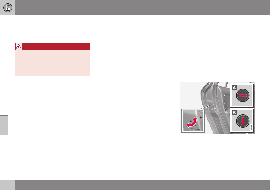
Manual locking

In certain situations (e.g., if there is no electri-

cal current in the vehicle), the doors can be

locked manually.

The detachable key blade (p. 128) can be

used in the lock cylinder in the driver's door

to lock that door.
The other doors do not have lock cylinders

and the slot on the rear edge of each door

has to be used to lock it. This will lock the

door from the outside but it can still be

opened from inside the vehicle. To do so:

Manually locking a door

Insert the key blade into the slot and turn

it 90 degrees to lock that door (the slot in

a particular door locks that door only).

06 Locks and alarm

06

135

In the horizontal position, the door cannot

be opened from the outside.
In the vertical position, the door can be

opened from the inside and the outside.

NOTE

If the manual child safety lock (p. 56) is

activated for a rear side door and that door

is also locked manually, the door cannot

be opened from the outside or inside. The

door can only be unlocked with the remote

key or the central locking button.

Related information

Remote key – replacing the battery

(p. 129)

Locking/unlocking – from inside

From inside the vehicle (central locking
button)

Unlocking

The vehicle can be unlocked from inside the

vehicle in two ways:

By pressing the unlock button 

.

Locking

Press the lock button 

 after the front

doors have been closed.

Each door can be locked individually with

the lock button on the respective doors.

The door must be closed first.

Alternative locking when parking

The central locking button on the driver's

door can also be used to lock the vehicle

when you leave it. To do so:
1. Open the door.
2. Press the lock section of the button.
3. Close the door. This will lock the vehicle

completely and arm the alarm.

NOTE

Please be aware that locking the vehicle in

this way makes it possible to lock the

remote key in the passenger compartment.

To help avoid this, lock the vehicle from

the outside by pressing the lock button on

the remote key.
If the vehicle is locked using the central

locking button, be sure that the remote key

is in your possession before closing the

door.

Automatic relocking

Automatic locking

Related information

Locking/unlocking – from the outside

(p. 134)

Alarm – general information (p. 136)

Remote key – functions (p. 127)

06 Locks and alarm

06

136

Locking/unlocking – glove

compartment

The glove compartment can only be locked

and unlocked using the detachable key blade

in the remote key. For information on remov-

ing the key blade from the remote key, see

Detachable key blade – detaching/reinserting

(p. 128).

Insert the key blade in the glove compart-

ment lock.
Turn the key blade 90 degrees clockwise.

Remove the key blade from the lock.

Alarm – general information

The alarm system provides a warning if an

attempt is made to break into the vehicle.
The alarm is automatically armed (p. 137)

whenever the vehicle is locked with the

remote key.
When armed, the alarm continuously monitors

a number of points on the vehicle. The follow-

ing conditions will trigger the alarm:

The hood is forced open.

A door is forced open.

The ignition slot is tampered with.

An attempt is made to start the vehicle

with a non-approved key (a key not

coded to the car's ignition).

The battery is disconnected (while the

alarm is armed).

The siren is disconnected when the alarm

is disarmed.

A message will appear in the information dis-

play if a fault should occur in the alarm sys-

tem. Contact a trained and qualified Volvo

service technician.

NOTE

Do not attempt to repair any of the compo-

nents in the alarm system yourself. This

could affect the insurance policy on the

vehicle.

Related information

Alarm – turning off (p. 138)

Alarm signal (p. 138)

Alarm indicator (p. 137)

06 Locks and alarm

06

137

Alarm indicator

The status of the alarm system is indicated by

the red indicator light on the dashboard (see

illustration):

Indicator light off: the alarm is not

armed (p. 137)

The indicator light flashes at one-second

intervals: the alarm is armed

The indicator light flashes rapidly before

the remote key is inserted in the ignition

slot and the ignition is put in mode I: the

alarm has been triggered.

Related information

Alarm – general information (p. 136)

Alarm – turning off (p. 138)

Alarm signal (p. 138)

Alarm – arming/disarming

The alarm system provides a warning if an

attempt is made to break into the vehicle.

Arming the alarm

Press the Lock button on the remote key.

One long flash of the turn signals will con-

firm that the alarm (p. 136) is armed.

Alarm confirmation settings can be changed
in MY CAR, under 

Car settings

Lock

settings

Keyless entry

. For a description

of the menu system, see My Car – introduc-

tion (p. 66).

USA FCC ID: MAYDA 5823(3)

This device complies with part 15 of the FCC

rules. Operation is subject to the following

conditions: (1) This device may not cause

harmful interference, and (2) this device must

accept any interference received, including

interference that may cause undesired opera-

tion.

 Canada IC: 4405A-DA 5823(3)

This device is subject to the following condi-

tions: (1) this device may not cause interfer-

ence, and (2) this device must accept any

interference, including interference that may

cause undesired operation of the device.

Disarming the alarm

Press the Unlock button on the remote

key.
> Two short flashes from the car's direc-

tion indicators confirm that the alarm

has been deactivated and that all

doors are unlocked.

Related information

Alarm indicator (p. 137)

Alarm signal (p. 138)

Alarm – turning off (p. 138)

Alarm-related functions (p. 138)

06 Locks and alarm

06

138

Alarm signal

An audible (p. 136) signal is given by a battery

powered siren. The alarm cycle lasts for

30 seconds.

The visual alarm signal is given by flashing all

turn signals for approximately 5 minutes or

until the alarm is turned off.

Related information

Alarm indicator (p. 137)

Alarm – arming/disarming (p. 137)

Alarm – turning off (p. 138)

Alarm – turning off

The alarm system provides a warning if an

attempt is made to break into the vehicle.

If the alarm is sounding, it can be stopped by

pressing the Unlock button on the remote key

or by inserting the remote key in the ignition

slot. Two short flashes from the car's turn sig-

nals confirm that the alarm has been turned

off.

Related information

Alarm indicator (p. 137)

Alarm – arming/disarming (p. 137)

Remote key – replacing the battery

(p. 129)

Alarm-related functions

The following is general information regarding

the alarm system in your vehicle.

Automatic re-arming

Remote key not functioning
If the remote key is not functioning properly,

the alarm can be turned off and the vehicle

can be started as follows:
1. Open the driver's door with the key blade.

This will trigger the alarm.

2. To turn off the alarm, insert the remote

key into the ignition slot (also on vehicles

with the optional keyless drive).

3. Start the engine.

07 Driver support

07

}}

*


Option/accessory, for more information, see Introduction.

141

Active chassis* (Four C)

Active chassis, Four-C (Continuously

Controlled Chassis Concept), regulates the

characteristics of the shock absorbers so that

the vehicle's driving characteristics can be

adjusted. There are three settings: Comfort,

Sport and Advanced.

Operation

Chassis settings

Use the buttons in the center console to

change setting. The setting in use when the

engine is switched off is activated the next

time the engine is started.

Comfort

Comfort mode offers a somewhat softer ride

and the transmission shifts gears at lower

rpm. This mode is particularly suitable for

long-distance highway driving. The indicator

light in the button will be on when this mode

is selected.

Sport

In this mode, the vehicle's body sway is

reduced during cornering and steering

response is more immediate. The transmis-

sion shifts up at higher rpm for sportier driv-

ing. The indicator light in the button will be on

to indicate that Sport mode has been

selected.

Advanced

In this mode, body sway in curves is minimal

and steering response is very direct. Gear

shifting is done at high rpm in each gear for

dynamic and active driving.

Related information

Adjustable steering force* (p. 145)

Stability system – introduction

The Electronic Stability Control (ESC) system

consists of a number of functions designed to

help reduce wheel spin, counteract skidding

and to generally help improve directional sta-

bility.

A pulsating sound will be audible

when the system is actively operat-

ing and is normal. Acceleration will

also be slightly slower than normal.

WARNING

ESC is a supplementary aid and cannot

deal with all situations or road conditions.
The driver is always responsible for oper-

ating the vehicle in a safe manner in

accordance with current traffic regulations.

ESC consists of the following functions:

Traction control

Spin control

Active Yaw Control

Traction Control (TC)

This function is designed to help reduce

wheel spin at low speeds by transferring

power from a drive wheel that begins to lose

traction to the wheel on the opposite side of

the vehicle (on the same axle).

||

07 Driver support

07

142

Spin Control (SC)

The SC function is designed to help prevent

the drive wheels from spinning while the vehi-

cle is accelerating.

Active Yaw Control (AYC)

This function helps maintain directional stabil-

ity, for example when cornering, by braking

one or more of the wheels if the vehicle

shows a tendency to skid or slide laterally.

Trailer Stability Assist (TSA)

The TSA helps stabilize a vehicle that is tow-

ing a trailer when the vehicle and trailer have

begun to sway. See Trailer Stability Assist

(TSA) (p. 245) for more information.
This system is automatically deactivated if the

driver selects Sport mode.

Related information

Stability system – operation (p. 142)

Stability system – symbols and messages

(p. 143)

Trailer Stability Assist (TSA) (p. 245)

Stability system – operation

Operation

Sport mode

The stability system is always activated and

cannot be switched off.

However, the driver can

select Sport mode, which

offers more active driving

characteristics.
Sport mode can be selected

in the MY CAR menus, see

My Car – introduction (p. 66).
In Sport mode, the engine management sys-

tem monitors movement of the accelerator

pedal and steering wheel for sportier driving

by allowing more lateral movement of the rear

wheels before ESC is activated.
Under certain circumstances, such as when

driving with snow chains, or driving in deep

snow or loose sand, it may be advisable to

temporarily use Sport mode for maximum

tractive force.
If the driver releases pressure on the acceler-

ator pedal, ETC will also activate to help sta-

bilize the vehicle.
To switch to Sport mode:
Sport mode remains active until the driver

switches it off in the menu or until the engine

is switched off. ETC will return to normal

mode when the engine is restarted.

Related information

Stability system – introduction (p. 141)

Stability system – symbols and messages

(p. 143)

07 Driver support

07

}}

143

Stability system – symbols and

messages

Symbols and messages in the main
instrument panel
A text message can be erased by pressing

briefly the OK button on the turn signal lever.

Symbol Message

Description

ESC Temporarily OFF

The ESC system function has been temporarily reduced due to high brake disc temperature. The function

reactivates automatically when the brakes have cooled.

ESC Service required

The ESC system is not functioning properly.

Stop the vehicle in a safe place, turn off the engine and restart it.

If the message is still displayed when the engine has restarted, drive to an authorized Volvo work-

shop to have the system inspected.

and

"Message"

Read the message in the instrument panel.

Steady glow for

2 seconds.

The system is performing a self-diagnostic test.

||

07 Driver support

07

144

Symbol Message

Description

Flashing symbol.

ESC is actively functioning to help counteract wheel spin and/or a skid.

Steady glow.

Sport mode has been activated.
Please note that ESC is not deactivated at this time but its functionality is reduced.

WARNING

The stability system is intended to help

improve driving safety. It supplements, but

can never replace, the driver's judgment

and responsibility when operating the vehi-

cle. Speed and driving style should always

be adapted to traffic and road conditions.

Related information

Stability system – introduction (p. 141)

Stability system – operation (p. 142)

07 Driver support

07

*


Option/accessory, for more information, see Introduction.

145

Adjustable steering force*

Steering force increases with the speed of the

vehicle to give the driver enhanced sense of

control and stability. At low speed the vehicle

is easy to steer in order to facilitate parking,

etc.

Adjustable steering force*
Steering force can be changed under 

MY

CAR

Car settings

Steering wheel

force

. Select 

Low

Medium

 or 

High

. For a

description of the menu system, My Car –

introduction (p. 66).

NOTE

This steering force level menu function

cannot be accessed when the vehicle is in

motion.

NOTE

In certain situations, the power steering

may become too warm and will have to be

temporarily cooled down. While this is

happening, the power steering effect will

be reduced slightly and somewhat more

effort may be required to turn the steering

wheel.
If this occurs, a message will be displayed

in the instrument panel.

Related information

Active chassis* (Four C) (p. 141)

Road Sign Information (RSI)* –

introduction

RSI is a feature that helps the driver see road

signs with the posted speed limit.

Introduction

Examples of readable road signs

If the vehicle passes a sign showing the

speed limit, this will be displayed in the center

console.

WARNING

RSI does not function in all situations and

is only intended to provide supplementary

information.
The driver is always responsible for oper-

ating the vehicle safely.

Related information

Road Sign Information (RSI) – operation

(p. 146)

Road Sign Information (RSI) – limitations

(p. 146)

07 Driver support

07

146

*


Option/accessory, for more information, see Introduction.

Road Sign Information (RSI) –

operation

Speed limit information

When RSI registers a road sign showing the

speed limit, this sign is displayed as a symbol

on the instrument panel.

Settings in MY CAR

Possible settings in MY CAR

Displaying the speed limit indication can be

deactivated. To do so:

Deselect the alternative in MY CAR

Settings

Car settings

Road Sign

Information

 or cancel by pressing EXIT.

Speed alert

The driver can opt to be alerted if the vehicle

exceeds the posted speed limit by more than

3 mph (5 km/h). The alert is given when the

symbol with the posted speed limit in the

instrument panel begins to flash.
To activate speed alert:

Check the Speed alert box in MY CAR

Settings

Car settings

Speed alert

or cancel by pressing EXIT.

Related information

Road Sign Information (RSI)* – introduc-

tion (p. 145)

Road Sign Information (RSI) – limitations

(p. 146)

My Car – introduction (p. 66)

Road Sign Information (RSI) –

limitations

RSI's camera has the same limitations as the

human eye. See The camera’s limitations

(p. 183) for more information about the cam-

era's limitations.
Signs that indirectly indicate the speed limit

(such as a sign with a town's name and the

permitted speed limit) will not be registered

by RSI.
Other factors that may interfere with RSI

include:

Faded signs

Signs located in a curve

Twisted or damaged signs

Obstructed signs

Signs that are partially covered by snow,

ice, etc.

Related information

Road Sign Information (RSI)* – introduc-

tion (p. 145)

Road Sign Information (RSI) – operation

(p. 146)

The camera’s limitations (p. 183)

07 Driver support

07

}}

147

Cruise control (CC) – introduction

Cruise control is designed to assist the driver

by maintaining a set speed. It is primarily

intended for use on long straight roads in

steady traffic, such as on highways and other

main roads.

Operation

Steering wheel-mounted controls and display

Standby mode

Resume set speed

Deactivating

Activate/set speed

Selected speed (gray symbol indicates

standby mode)
Cruise control active: white symbol (gray

symbol indicates standby mode)

Related information

Cruise control (CC) – engaging and set-

ting speed (p. 147)

Cruise control (CC) – deactivating

(p. 149)

Cruise control (CC) – engaging and

setting speed

Cruise control is designed to assist the driver

by maintaining a set speed. It is primarily

intended for use on long straight roads in

steady traffic, such as on highways and other

main roads.

Engaging the cruise control function

Steering wheel-mounted controls and display

Standby mode

Resume set speed

Deactivating

Activate/set speed

Selected speed (gray symbol indicates

standby mode)
Cruise control active: white symbol (gray

symbol indicates standby mode)

||

07 Driver support

07

148

Before a speed can be set, the cruise control

system must be engaged (put in standby

mode).

Press the CRUISE button (1).
> The symbol   illuminates and the text

(---) mph

 (5) indicates that cruise con-

trol is in standby mode.

NOTE

Putting cruise control in standby mode

does not set a cruising speed.

Setting a speed
Use the 

 or 

 buttons set the vehicle's

current speed. The set speed is shown in the

display.

NOTE

Cruise control cannot be engaged at

speeds below 20 mph (30 km/h).

Adjusting the set speed
After a speed has been set, it can be
increased or decreased by using the 

 or 

buttons.
1. Press   or   briefly and release the

button to increase or decrease vehicle

speed by approximately 1 mph or 1 km/h.
> This will become the set speed when

the button is released.

2. Press and hold one of these buttons to

increase/decrease the speed in 1-mph or

1-km/h increments. Release the button

when you have reached the desired

speed.

NOTE

A temporary increase in speed by

pressing the accelerator pedal, for less

than 1 minute (e.g. when passing

another car), does not affect the cur-

rent cruise control setting. The vehicle

will automatically return to the previ-

ously set speed when the accelerator

pedal is released.

If one of the cruise control buttons is

kept depressed for more than approx.

1 minute cruise control is disengaged.

The engine must then be switched off

in order to reset cruise control.

Related information

Cruise control (CC) – introduction (p. 147)

Cruise control (CC) – deactivating

(p. 149)

07 Driver support

07

}}

149

Toggling between ACC and CC

(standard Cruise Control)

Adaptive Cruise Control (ACC) helps the

driver maintain a safe distance/time interval to

the vehicle ahead.

Switching from ACC to CC
This may be useful if, for example, the radar

sensor is obstructed in some way. See

Adaptive Cruise Control – limitations (p. 159)

for additional information.

Press and hold the 

 button; the symbol

in the instrument panel will switch from

 to 

.

> This activates the standard cruise control

function (see Cruise control (CC) – intro-

duction (p. 147)).

WARNING

Switching from ACC to CC means that:

Your vehicle will no longer automati-

cally maintain a set distance to a vehi-

cle ahead.

Only the set speed will be maintained

and the driver will have to apply the

brakes when needed.

Switching from CC to ACC
Switch off cruise control by pressing 

 once

or twice as needed according to the instruc-

tions in the previous section "Turning ACC off

completely." The next time the system is

switched on, ACC will be reactivated.

Related information

Adaptive Cruise Control – introduction

(p. 150)

Adaptive Cruise Control – function

(p. 151)

Cruise control (CC) – deactivating

Cruise control is designed to assist the driver

by maintaining a set speed. It is primarily

intended for use on long straight roads in

steady traffic, such as on highways and other

main roads.

Automatic deactivation
The cruise control is automatically deacti-

vated temporarily if one of the following

occurs:

If the speed drops below approximately

20 mph (30 km/h).

When the brake pedal is depressed.

If the gear selector is moved to position

N.

During wheel spin or wheel lock-up.

If the vehicle's speed is increased by

using the accelerator pedal for more than

1 minute.

Engine speed (rpm) is too high or too low.

The currently set speed will be saved in the

system's memory.

Temporary deactivation
The driver can temporarily deactivate the

cruise control by pressing 0. The saved

speed is shown in brackets in the information

display.

||

07 Driver support

07

150

Resume set speed
If the cruise control has been deactivated

temporarily, it can be reactivated by pressing

. The vehicle's speed returns to the most

recently set speed.

WARNING

There may be a significant increase in
speed after the 

 button has been

pressed.

Deactivation
The Cruise control is disengaged by pressing

 or by switching off the engine. The set

speed is cleared.

WARNING

Cruise control should not be used in heavy

traffic or when driving on wet or slippery

roads. Cruise control may not maintain set

speed on steep downgrades.

Related information

Cruise control (CC) – introduction (p. 147)

Cruise control (CC) – engaging and set-

ting speed (p. 147)

Adaptive Cruise Control – introduction

ACC is an optional system designed to assist

the driver by maintaining a set speed or a set

time interval to the vehicle ahead. It is primar-

ily intended for use on long straight roads in

steady traffic, such as on highways and other

main roads.

When the driver has set the desired speed

and the time interval to the vehicle ahead,

ACC functions as follows:

If there are no other vehicles in the lane

ahead of you, your vehicle will travel at

the set speed.

If ACC's radar sensor detects a slower

moving vehicle in the lane ahead, the sys-

tem will adapt your vehicle's speed to

help maintain the set time interval to the

vehicle ahead. When there are no longer

slower moving vehicles ahead, your vehi-

cle will accelerate to resume the set

speed.

If ACC is switched off completely or in

standby mode and your vehicle comes too

close to another vehicle ahead, the driver will

be warned by the Distance Alert system (see

Distance Alert – introduction (p. 164)).

WARNING

Adaptive Cruise Control cannot cover

all driving situations and traffic,

weather and road conditions. The

"Function" section provides informa-

tion about limitations that the driver

must be aware of before using this

feature.

This system is designed to be a sup-

plementary driving aid. It is not, how-

ever, intended to replace the driver's

attention and judgement. The driver is

responsible for maintaining a safe dis-

tance and speed and must intervene if

Adaptive Cruise Control does not

maintain a suitable speed or suitable

distance to the vehicle ahead.

Maintenance of ACC components may

only be performed by a trained and

qualified Volvo technician.

07 Driver support

07

}}

151

Operation

Controls and display

Resume previous settings.

Off/On/Standby mode

Decrease/increase time interval

Put in active mode and set a speed (each

additional press increases/decreases

speed by 1 mph (approximately 2 km/h))
Set speed (shown in green when active,

shown in white when in standby mode)
Time interval

ACC active (green symbol) or in standby

mode (white symbol)

Related information

Toggling between ACC and CC (standard

Cruise Control) (p. 149)

Cruise control (CC) – introduction (p. 147)

Adaptive Cruise Control – troubleshooting

(p. 163)

Adaptive Cruise Control – symbols and

messages (p. 161)

Adaptive Cruise Control – setting time

interval (p. 155)

Adaptive Cruise Control – setting speed

(p. 154)

Radar sensor (p. 159)

Adaptive Cruise Control (ACC) – Queue

Assist (p. 157)

Adaptive Cruise Control – passing

another vehicle (p. 157)

Adaptive Cruise Control – limitations

(p. 159)

Adaptive Cruise Control – function

(p. 151)

Adaptive Cruise Control – engaging

(p. 153)

Adaptive Cruise Control – deactivating

(p. 155)

Adaptive Cruise Control – function

Function

Function overview

1

Warning light, braking by driver required

Controls in steering wheel

Radar sensor in front grille

Adaptive Cruise Control consists of:

A cruise control system to maintain a set

speed

A system to maintain a set distance to the

vehicle ahead, which is expressed as a

time interval. For example, you can

choose to remain approximately 2 sec-

onds behind the vehicle ahead. The

actual distance required to maintain a

2-second interval will vary according the

speed of the vehicles.


Content   ..  6  7  8  9   ..