Volvo S60 Cross Country (2018 year). Instruction - part 4
INSTRUMENTS AND CONTROLS
* Option/accessory.
75
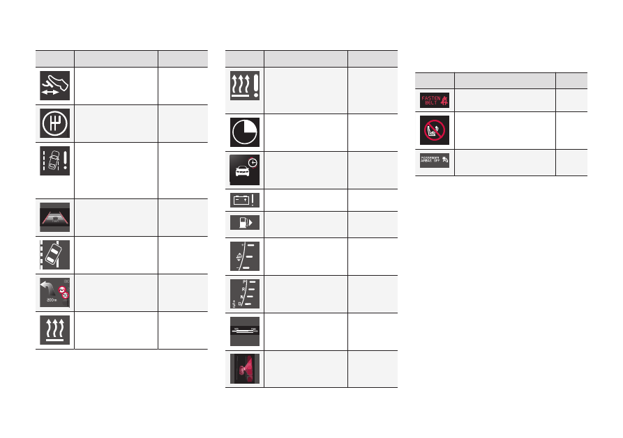
Symbol
Specification
See
Start/Stop
*
Start/Stop
*
Driver Alert System
*,
Lane Departure
Warning (LDW),
Lane Keeping Aid
(LKA)
Driver Alert System
*,
Lane Departure
Warning
*
Driver Alert System
*,
Lane Departure
Warning
*
Recorded speed
information
*
Engine block and
passenger compart-
ment heater
*
Symbol
Specification
See
Engine block heater
and passenger com-
partment heater
*
Service required
Activated timer
*
Activated timer
*
Low battery
Fuel filler flap, right-
hand side
Gear shift indicator
Gear positions
Measuring the oil
level
Park Assist Pilot -
PAP
*
Information symbols in the roof console
display
Symbol
Specification
See
Seatbelt reminder
Airbag, passenger seat,
activated
Airbag, passenger seat,
deactivated
Related information
•
Combined instrument panel - meaning of
indicator symbols (p. 67)
•
Combined instrument cluster - meaning of
warning symbols (p. 69)
•