Volkswagen Golf / Golf GTI / Jetta. Manual - part 551
 

  Index      Volkswagen     Volkswagen Golf / Golf GTI / Jetta - service repair manual 1999-2005 year


Search            copyright infringement  


Content   ..  549  550  551  552   ..


Volkswagen Golf / Golf GTI / Jetta. Manual - part 551


n

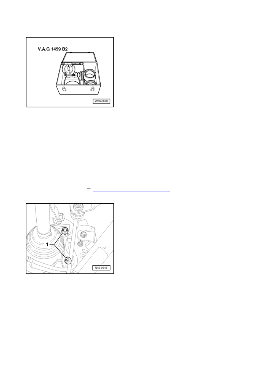
Supplementary set V.A.G 1459 B/2  


n

Bell E-40  


n

Press piece E-6-1  


n

Press piece E-13-1  


n

Thrust pad E-39  


- Remove wheel. 

- First remove drive axle 


42-7, Rear drive axle, removing 

and installing

 . 

- Remove bolts - 1 - from brake caliper and take off brake 
caliper. 

- Secure brake caliper to body. 

- Remove phillips-head screw for brake disc and take out 
brake disc. 

- Disconnect ABS vehicle speed sensor from trail arm 
housing. 

Pressing out hub


Trailing arm and transverse links (all-wheel drive vehicles), assembly overview


- Install thrust disc - 1 - as shown in illustration. 

1 - Thrust disc E-39 ; Position thrust disc so that it lies 
completely on bolt heads 2 .  

- Center assembly with clip E-76-2 . 

1 - Piston cylinder HKZ-15 with hydraulic press piece E-0-
204-T  

2 - Centering with clip E-76-2  

Note

n

Place engine/transmission jack V.A.G1383/A , or 
similar, underneath to ensure safety (danger of 
accident through falling parts when pressing out the 
wheel hub).  


Trailing arm and transverse links (all-wheel drive vehicles), assembly overview


- Install support - 1 - , piston cylinder - 2 - with pull rod - 3 - 
and special nut - 4 - 

1 - Bell E-40  

2 - Piston cylinder HKZ-15  

3 - Removal rods E-0-217  

4 - Special nut E-8-214  

5 - High pressure hose with quick release coupling 

6 - Thrust pad E-39  

- Build-up pressure with foot pump. 

- Check that all tools are correctly centered. 

- Press wheel hub out through wheel bearing by operating 
pump. 

Pressing out wheel bearing


- Remove circlip - 1 - 

Trailing arm and transverse links (all-wheel drive vehicles), assembly overview


- Position thrust piece - 1 - on back of wheel bearing. 

- Install piston cylinder - 2 - with pull rod - 3 - and special 
tool - 4 - 

1 - Press piece E-5  

2 - Piston cylinder HKZ-15  

3 - Removal rods E-0-217  

4 - Special nut E-8-214  

5 - Bell E-44  

- Build-up pressure with foot pump. 

- Check that all tools are correctly centered. 

- Press out wheel bearing by operating pump. 

- Pull bearing inner race off from wheel hub.  

Pressing in wheel bearing 

- Position wheel bearing on wheel bearing housing. 

Trailing arm and transverse links (all-wheel drive vehicles), assembly overview


Content   ..  549  550  551  552   ..