Volkswagen Golf / Golf GTI / Jetta. Manual - part 503
 

  Index      Volkswagen     Volkswagen Golf / Golf GTI / Jetta - service repair manual 1999-2005 year


Search            copyright infringement  


Content   ..  501  502  503  504   ..


Volkswagen Golf / Golf GTI / Jetta. Manual - part 503


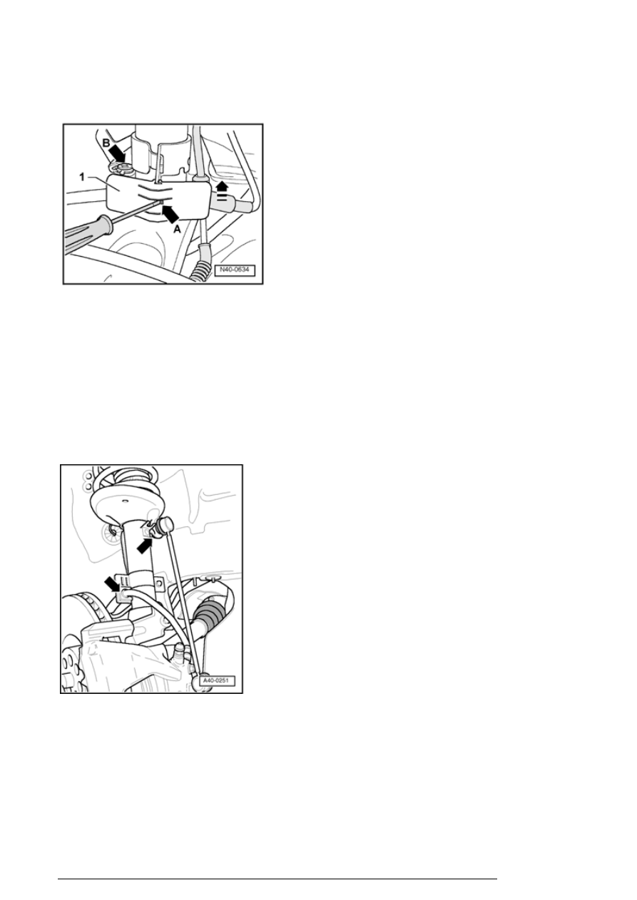
- For vehicles with brake wear pad indicator, disconnect 
connector - 1 - 

- Remove heat shield - 1 - 

- To do this push lip - arrowA - with a screwdriver in and 
push at the same time the heat shield  - 1 - upward in 
direction of arrow. 

- For vehicles with brake wear pad indicator remove bolt  
arrowB - 
to remove support for brake wear pad indicator. 

The following three steps are necessary only for 
vehicles with modified stabilizer bar mounting. 

- Remove upper hex nuts of connecting links from left and 
right suspension strut. 

- Pull out clamp on brake hose bracket and release brake 
hose. 

- Release speed sensor wiring from front suspension strut.  

Continued for all vehicles

Front suspension, servicing


- Remove securing bolts - 2 - from brake caliper. 

- Remove brake caliper and hang up on structure.  

- Remove connecting link from control arm. 

- Release speed sensor wiring from suspension strut. 

Right suspension strut 

Additional work is required if right suspension strut is to be 
removed 

- Remove noise insulation. 

- Disconnect drive axle from transmission axle flange. 

The following work sequence is valid for both sides

- Separate wheel bearing housing/suspension strut bolted 
connection. 

Front suspension, servicing


- Insert Spreader 3424 into slot - arrow - 

- Turn ratchet handle through 90   and pull off 3424 . 

- Press brake disc in direction of suspension strut by hand. 

Otherwise the shock absorber tube could catch in wheel 
bearing housing hole. 

- Pull wheel bearing housing off shock absorber downward. 

Remove hex nut from upper shock absorber mount 

1 - Ratchet (commercially available) 

2 - T10001/8  

3 - T10001/11  

4 - T10001/5  

- Remove strut. 

Installing


- Install suspension strut. 

- Remove spreader 3424 . 

- Tighten bolted union wheel bearing housing/suspension 
strut. 

Front suspension, servicing


Further installation of suspension strut is performed in 
reverse order 

Tightening torques:


12-point nut for upper spring plate 

60 Nm

Hex. nut for wheel bearing housing 

60 Nm plus an additional 

1

 / 

4

 turn (90   ) 

Coupling rod to suspension strut 

50 Nm plus an additional 

1

 / 

4

 turn (90   ) 

Front suspension strut, servicing


Special tools, testers and auxiliary items 
required
 

n

Torque wrench V.A.G1332  


n

Spring compressor V.A.G1752/1  


n

Spring holder V.A.G1752/4  


n

Shock absorber set T10001  

Front suspension, servicing


Content   ..  501  502  503  504   ..