Volkswagen Golf / Golf GTI / Jetta. Manual - part 31
 

  Index      Volkswagen     Volkswagen Golf / Golf GTI / Jetta - service repair manual 1999-2005 year


Search            copyright infringement  


Content   ..  29  30  31  32   ..


Volkswagen Golf / Golf GTI / Jetta. Manual - part 31


15-19


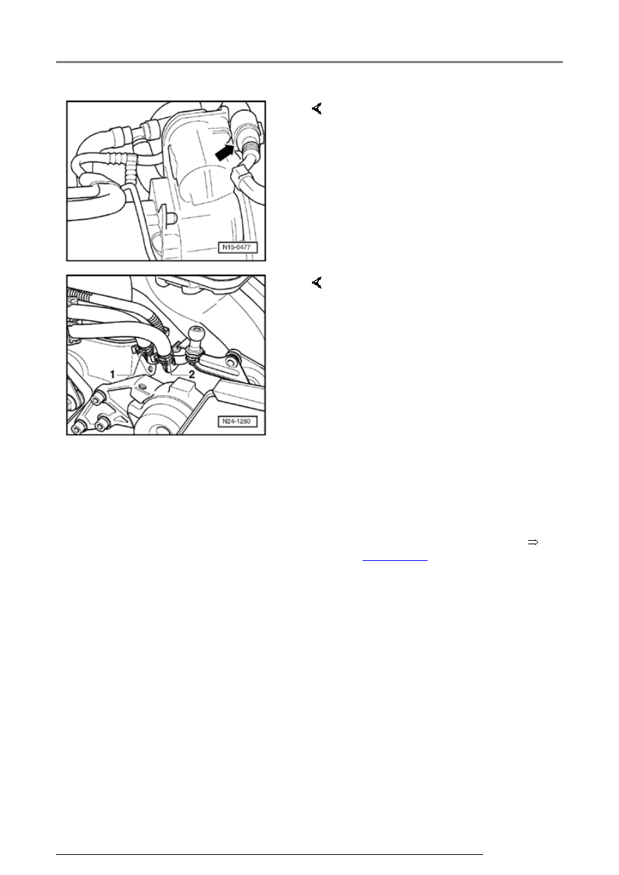
-  Disconnect 6-pin connector from 

throttle valve control module 
(arrow). 

-  Open and close expansion tank 

cap to release pressure in cooling 
system. 

-  Pull coolant hoses off throttle 

valve control module and seal 
hose ends. 


WARNING!


Fuel system is under pressure! 
Before opening the system place 
a cloth around the connection. 
Then release pressure by 
carefully loosening the 
connection.


-  Pull fuel supply hose -1- (with 

white marking) and fuel return 
hose -2- (with blue marking) off 
fuel rail and collect fuel that may 
leak out with a cloth. 

-  Seal lines to avoid contamination 

of fuel system. 

-  Observe rules for cleanliness 


Page 20-14

 . 

Cylinder head, servicing

15-20


-  Remove retaining frame on 

cylinder head for fuel lines and 
wiring harness (arrows). 


Note:  

Press buttons on hose couplings to 
do so.
 

-  Disconnect vacuum hoses 

(arrows) from intake manifold. 

-  Remove rearmost bolt -1- for 

intake manifold support. 

-  Unclip pressure hose (between 

combi-valve and secondary air 
pump motor) and all other lines 
from retainers on intake manifold 
and cylinder head cover. 

-  Remove guide on cover for 

coolant hoses and wiring harness 


Page 15-11

 , item - 1 -. 

Cylinder head, servicing

15-21


-  Remove Ground connection on support of 

combi-valve 


Page 26-25

 , item - 9 -. 


-  Disconnect vacuum hose from variable intake 

manifold change-over vacuum actuator. 


-  Remove two lateral intake manifold support 

bolts. 


-  Remove center, left and right insulation trays:  


Repair Manual, Body Exterior, Repair Group 

50


-  Disconnect connectors from thermal switch and 

coolant fan. 


-  Removing front bumper: 


Repair Manual, Body Exterior, Repair Group 

63


-  Bring lock carrier into service position: 


Repair Manual, Body Exterior, Repair Group 

50


-  Unscrew dipstick guide tube from intake 

manifold. 


-  Remove intake manifold securing bolts and 

remove intake manifold together with throttle 
valve control module. 

Cylinder head, servicing

15-22


-  Remove intake manifold and place on a suitable 

surface so that vacuum actuator is not 
damaged. 


   Note:  


   Seal the intake ports in the intake manifold or in 

the cylinder head with a clean cloth. 


-  Remove cylinder head cover. 


   Installing  


   Install in reverse sequence ; note the following 

points:  


   Note:  


 Replace cylinder head cover if damaged or 

leaking. 


 First bolt intake manifold to cylinder head. Then 

tighten both bolts of the manifold support.  


 Ensure tight fit of fuel hoses. 


-  If necessary replenish coolant 


Page 19-15

 . 


-  Check DTC memory: 


Repair Manual, 2.8 Liter VR6 4V Fuel Injection 

& Ignition, Engine Code(s): BDF, Repair Group 
01


Cylinder head, servicing


Content   ..  29  30  31  32   ..