Volkswagen 01M Transmission. Manual - part 114
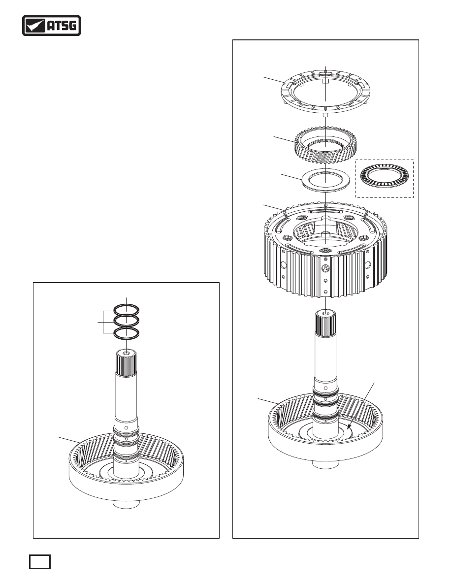
115
118
118
113
116
REAR VIEW
112
111
117
115 INPUT SHAFT SEALING RINGS (3 REQUIRED).
118 FRONT PLANETARY RING GEAR AND INPUT SHAFT ASSEMBLY.
Figure 142
Figure 143
86
Copyright © 2010 ATSG
AUTOMATIC TRANSMISSION SERVICE GROUP
Technical Service Information
FRONT PLANETARY ASSEMBLY (CONT'D)
COMPONENT REBUILD (CONT'D)
8. Install three new sealing rings in the grooves
of input shaft, as shown in Figure 142.
9. Install the front planetary carrier assembly into
planetary ring gear, as shown in Figure 143, by
rotating into position.
Note: Ensure number 4 thrust washer and
number 3 thrust bearing race are in place.
10. Install the number 3 thrust bearing, as shown
in Figure 143, with needles facing down.
11. Install the front planetary sun gear, as shown
in Figure 143, by rotating into position.
12. Install the number 2 thrust washer, as shown
in Figure 143, and retain with Trans-Jel®.
13. Set the completed front planetary assembly
aside for the final assembly process, as shown
in Figure 144.
111 NUMBER 2 THRUST WASHER.
112 FRONT PLANETARY SUN GEAR.
113 FRONT PLANETARY CARRIER ASSEMBLY.
116 NUMBER 3 THRUST BEARING.
117 NUMBER 3 THRUST BEARING RACE.
118 FRONT PLANETARY RING GEAR AND INPUT SHAFT ASSEMBLY.
Componet Rebuild
Continued on Page 87
WWW.ALL-TRANS.BY