Toyota Corolla Cross (2024 year). Manual in english - page 8
 

  Index      Toyota     Toyota Corolla Cross (2024 year). Manual in english


Search            copyright infringement  


Content      ..     6      7      8      9     ..


Toyota Corolla Cross (2024 year). Manual in english - page 8


225

4-5. Using the driving support systems

4

Dr

iv

ing

The proactive driving assist 

can be enabled/disabled 

through a customize setting. 

(

P.459)

The following settings of the 

proactive driving assist can be 

changed through customize 

settings. (

P.459)

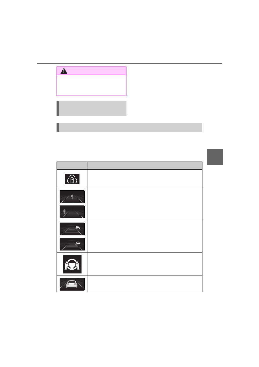
Depending on the situation, the following indicators or icons will be 

displayed.
Some icons cannot be displayed unless the display is changed to 

the driving safety support function information screen.

WARNING

When entering a curve, driving 

around a curve and a few sec-

onds after driving around a 

curve

Changing proactive driv-

ing assist settings

System operation display

Icon

Meaning

White: Monitoring for detectable objects

Green: Detectable object crossing the road or detectable 

object on the side of the road assistance operating

A pedestrian has been detected as crossing the road or on 

the side of the road and brake or steering assistance is 

operating

A vehicle has been detected on the side of the road and 

brake or steering operation assistance is being performed

Steering operation assistance is being performed to pre-

vent the vehicle from approaching too close to a detectable 

object on the side of the road

Preceding vehicle deceleration assistance is being per-

formed

226

4-5. Using the driving support systems

Hands off steering wheel warn-
ing operation

In the following situations, a mes-
sage urging the driver to grip the 
steering wheel and the icon shown 
in the illustration will be displayed on 
the display to warn the driver. If the 
system detects that the steering 
wheel is held, the warning will be 
canceled. When using the system, 
make sure to grip the steering wheel 
firmly, regardless of whether the 
warning is operating or not.

When assistance to a detectable 
object crossing the road or assis-
tance to a detectable object on the 
side of the road is performed and 
the system determines the driver 
is not holding the steering wheel

If no operations are detected for a 
certain amount of time, a buzzer will 
sound, the warning will operate. 
This warning may also operate if the 
driver only operates steering wheel 
a small amount continuously.

Warning operation after preced-
ing vehicle deceleration assis-
tance has ended

After preceding vehicle decelera-
tion assistance has ended, if the 

driver does not operate the brake 
pedal or accelerator pedal and the 
vehicle approaches the preceding 
vehicle, the display will flash and a 
buzzer will sound to urge the driver 
to decelerate. If the system deter-
mines that the driver is operating the 
brake pedal or accelerator pedal, 
the warning will be canceled.

Warning to maintain appropriate vehicle-to-vehicle dis-
tance

Curve deceleration assistance is being performed

Icon

Meaning

227

4-5. Using the driving support systems

4

Dr

iv

ing

*

: If equipped

When the front camera 

detects a sign or information 

of a sign is available from the 

navigation system, the sign 

will be displayed on the dis-

play.

Multiple signs can be dis-

played.

Depending on the specifications of 

the vehicle, the number of dis-

played signs may be limited.

Operating conditions of sign 

display

Signs will be displayed when the fol-

lowing conditions are met:

The system has detected a sign

In the following situations, a dis-

played sign may stop being dis-

played:

When a new sign has not been 

detected for a certain distance

When the system determines that 

the road being driven on has 

changed, such as after a left or 

right turn

Situations in which the display 

function may not operate prop-

erly

In the following situations, the RSA 

system may not operate properly 

and may not detect signs or may 

display the incorrect sign. However, 

this does not indicate a malfunction.

When a sign is dirty, faded, tilted 

or bent

When the contrast of an electronic 

sign is low

When all or part of a sign is hidden 

by a tree, utility pole, etc.

When a sign is detected by the 

front camera for a short amount of 

time

When the driving state (turning, 

changing lanes, etc.) is judged 

incorrectly

RSA (Road Sign 

Assist)

*

The RSA system detects 

specific road signs using 

the front camera and/or nav-

igation system (when speed 

limit information is avail-

able) and warns the driver 

via displays and buzzers.

WARNING

For safe use

Driving safely is solely the 

responsibility of the driver. Pay 

careful attention to the sur-

rounding conditions in order to 

ensure safe driving.

Do not rely solely upon the 

RSA. The RSA assists the 

driver by providing road sign 

information, but it is not a 

replacement for the driver’s own 

vision and awareness. Driving 

safely is solely the responsibility 

of the driver. Pay careful atten-

tion to the surrounding condi-

tions in order to ensure safe 

driving.

Situations in which the RSA 

should not be used

When it is necessary to disable 

the system: 

P.194

Situations in which the sys-

tem may not operate properly

Situations in which the sensors 

may not operate properly: 

P.198

Display Function

228

4-5. Using the driving support systems

When a sign is immediately after a 
freeway junction or in an adjacent 
lane just before merging

When stickers are attached to the 
rear of a preceding vehicle

When a sign similar to a system 
compatible sign is detected as a 
system compatible sign

When a speed limit sign for a 
frontage road is within detection 
range of the front camera

When driving around a round-
about

When a sign intended for trucks, 
etc. is detected

When a sign is with supplimental 
sign(End point, day of week, time 
etc.)

When a sign is within road works 
area

When the navigation system map 
data is out of date

When the navigation system can-
not be used

In this case, the speed limit signs 
displayed on the multi-information 
display and navigation system dis-
play may differ.

In the following situations, the 
RSA system will output a warn-
ing to notify the driver.

If the vehicle speed exceeds 
the speed warning threshold 
of the speed limit sign dis-
played on the display, the sign 
display will be emphasized 
and a buzzer will sound.

When the RSA system 
detects a do not enter sign 
and determines that the vehi-
cle has entered a no-entry 

area, the do not enter sign 
displayed on the display will 
flash and a buzzer will sound.

Operating conditions of the 
notification functions

Excess speed notification function

This function will operate when the 
following condition is met:
• A speed limit road sign is recog-

nized by the system.

No entry notification function

This function will operate when all of 
the following conditions are met:
• More than one no entry road signs 

are recognized by the system 
simultaneously.

• The vehicle is passing between no 

entry road signs recognized by the 
system.

The following types of road 
signs can be displayed.

However, non-standard or recently 
introduced traffic signs may not be 
displayed.

Notification function

Types of road signs sup-
ported

Speed limit

Do Not Enter

No U-turn

229

4-5. Using the driving support systems

4

Dr

iv

ing

Depending on the specifica-

tions of the vehicle, signs may 

be displayed overlapping.

The following settings of the 

RSA can be changed through 

customize settings. (

P.459)

No Turn On Red

Stop

Yield

Warning

Changing RSA settings

Dynamic radar cruise 

control

This dynamic radar cruise 

control detects the pres-

ence of vehicles ahead, 

determines the current vehi-

cle-to-vehicle distance, and 

operates to maintain a suit-

able distance from the vehi-

cle ahead. The desired 

vehicle-to-vehicle distance 

can be set by operating the 

vehicle-to-vehicle distance 

switch.
Use the dynamic radar 

cruise control only on high-

ways and expressways.

WARNING

For safe use

Driving safely is solely the 

responsibility of the driver. Do 

not overly rely on this system, 

and pay careful attention to the 

surrounding conditions in order 

to ensure safe driving.

The dynamic radar cruise con-

trol provides driving assistance 

to reduce the driver’s burden. 

However, there are limitations to 

the assistance provided.

Read the following items carefully. 

Do not overly rely on this system 

and always drive carefully.
Conditions under which the sys-

tem may not operate correctly: 

P.235

230

4-5. Using the driving support systems

WARNING

Set the speed appropriately 

according to the speed limit, 

traffic flow, road conditions, 

weather conditions, etc. The 

driver is responsible for confirm-

ing the set speed.

Even if the system is operating 

correctly, the condition of a pre-

ceding vehicle as recognized by 

the driver and detected by the 

system may differ. Therefore, it 

is necessary for the driver to 

pay attention, assess risks, and 

ensure safety. Over-reliance on 

this system to drive the vehicle 

safely may lead to an accident 

resulting in death or serious 

injury.

Precautions for the driving 

assist systems

Observe the following precau-

tions, as there are limitations to 

the assistance provided by the 

system. Over-reliance on this sys-

tem may lead to an accident 

resulting in death or serious injury.

Details of support provided for 

the driver’s vision

The dynamic radar cruise control 

is only intended to help the driver 

in determining the distance 

between the driver’s own vehicle 

and a designated preceding vehi-

cle. It is not a system which allows 

for careless or inattentive driving, 

and is not a system which assists 

in poor visibility conditions.
The driver must pay attention to 

their surroundings, even when the 

vehicle stops.

Details of support provided for 

the driver’s judgement

The dynamic radar cruise control 

determines whether the distance 

between the driver’s own vehicle 

and a designated preceding vehi-

cle is within a set range. It is not 

capable of making any other type 

of judgement. Therefore, it is 

absolutely necessary for the 

driver to remain vigilant and to 

determine whether or not there is 

a possibility of danger.

Details of support provided for 

the driver’s operation

The dynamic radar cruise control 

does not include functions which 

will prevent or avoid collisions 

with vehicles ahead of your vehi-

cle. Therefore, if there is ever any 

possibility of danger, the driver 

must take immediate and direct 

control of the vehicle and act 

appropriately in order to ensure 

safety.

Situations in which the 

dynamic radar cruise control 

should not be used

Do not use the dynamic radar 

cruise control in the following situ-

ations. As the system will not be 

able to provide appropriate con-

trol, using it may lead to an acci-

dent resulting in death or serious 

injury.

Roads where there are pedes-

trians, cyclists, etc.

When driving on a highway or 

expressway entrance or exit

When the approach warning 

sounds frequently

Situations in which the sensors 

may not operate properly: 

P.198

Situations in which the lane may 

not be detected: 

P.194

231

4-5. Using the driving support systems

4

Dr
iv

ing

Constant speed cruising:
When there are no vehicles ahead

The vehicle drives at the speed set by the driver.

If the set vehicle speed is exceeded while driving down a hill, the set vehicle 
speed display will blink and a buzzer will sound.

Deceleration and follow-up cruising:
When a preceding vehicle driving slower than the set vehicle 
speed is detected

When a vehicle is detected driving ahead of your vehicle, the vehicle auto-
matically decelerates and if a greater reduction in vehicle speed is neces-
sary, the brakes are applied (the stop lights will come on at this time). The 
vehicle is controlled to maintain the vehicle-to-vehicle distance set by the 
driver, in accordance with changes in the speed of the preceding vehicle. If 
vehicle deceleration is not sufficient and the vehicle approaches the vehicle 
ahead, the approach warning will sound.

Acceleration:
When there are no longer any preceding vehicles driving slower 
than the set vehicle speed

The vehicle accelerates until the set vehicle speed is reached and then 
resumes constant speed cruising.

Starting off:
If a preceding vehicle stops, the vehicle will also stop (controlled 
stop). After the preceding vehicle starts off, pressing the “RES” 
switch or depressing the accelerator pedal will resume follow-up 
cruising (start off operation). If a start off operation is not per-

Basic functions

232

4-5. Using the driving support systems

formed, the controlled stop will continue.

Meter display

Multi-information display

Set vehicle speed

Indicator

Switches

Driving assist mode select 
switch

Driving assist switch

“+” switch / “RES” switch

“-” switch

Cancel switch

Vehicle-to-vehicle distance 
switch

1

Press the driving assist mode 
select switch to select 
dynamic radar cruise control.

The dynamic radar cruise control 
indicator will illuminate.

2

Using the accelerator pedal, 
accelerate or decelerate to 
the desired vehicle speed 
(approximately 20 mph [30 
km/h] or more), and press the 
driving assist switch to set 
the set vehicle speed.

The set vehicle speed will be dis-
played on the multi-information dis-
play.

The vehicle speed at the moment 
the switch is released will be the set 

System Components

Using the dynamic radar 
cruise control

Setting the vehicle speed

233

4-5. Using the driving support systems

4

Dr
iv

ing

vehicle speed.

Adjusting the set vehicle 
speed using the switches

To change the set vehicle 
speed, press the “+” switch or “-” 
switch until the desired speed is 
displayed.

1

Increase set vehicle speed

2

Decrease set vehicle speed

Short press adjustment: Press the 
switch

Long press adjustment: Press and 
hold the switch until the desired set 
vehicle speed is reached.

The set vehicle speed will 
increase or decrease as follows:

For the U.S.A.

Short press adjustment: Increases 

or decreases by 1 mph (1.6 km/h) 
each time the switch is pressed

Long press adjustment: Increases 
or decreases in 1 mph (1.6 km/h) 
increments continuously while the 
switch is pressed and held

For Canada

Short press adjustment: By 1 km/h 
(0.6 mph) or 1 mph (1.6 km/h) each 
time the switch is pressed

Long press adjustment: Increases 
or decreases in 5 km/h (3.1 mph) or 
5 mph (8 km/h) increments continu-
ously while the switch is pressed 
and held

Increasing the set vehicle 
speed using the accelerator 
pedal

1

Depress the accelerator 
pedal to accelerate the vehi-
cle to the desired vehicle 
speed.

2

Press the “+” switch.

1

Press the cancel switch or 
driving assist switch to cancel 
control.

Control will also be canceled if the 

Adjusting the set vehicle 
speed

Canceling/resuming con-
trol

234

4-5. Using the driving support systems

brake pedal is depressed.

(If the vehicle has been stopped by 
system control, depressing the 
brake pedal will not cancel control.)

2

Press the “RES” switch to 
resume control.

Each time the switch is pressed, the vehicle-to-vehicle distance set-
ting will change as follows:

If a preceding vehicle is detected, the preceding vehicle mark will be dis-
played.

The actual vehicle-to-vehicle distance varies in accordance with the vehicle 
speed. Also, when the vehicle is stopped by system control, it will be 
stopped at a certain distance from the preceding vehicle, depending on the 
situation, regardless of the setting.

Operating conditions

The shift lever is in D.

The desired set speed can be set 
when the vehicle speed is approx-
imately 20 mph (30 km/h) or more.

• If the vehicle speed is set while 

driving at below approximately 20 
mph (30 km/h), the set vehicle 
speed will be approximately 20 
mph (30 km/h).

• If the vehicle speed is set while 

driving at a speed that exceeds 
the system’s upper limit, the set 
vehicle speed will be the system’s 
upper limit.

Accelerating after setting the 
vehicle speed

As with normal driving, acceleration 
can be performed by depressing the 
accelerator pedal. After accelerat-
ing, the vehicle will return to the set 

Changing the vehicle-to-vehicle distance

Illustration 

Number

Vehicle-to-vehicle 

distance

Approximate Distance (Vehicle 

Speed: 60 mph [100 km/h])

1

Short

Approximately 85 ft. (25 m)

2

Medium

Approximately 100 ft. (30 m)

3

Long

Approximately 145 ft. (45 m)

4

Extra long

Approximately 200 ft. (60 m)

235

4-5. Using the driving support systems

4

Dr
iv

ing

vehicle speed. However, while in 
vehicle-to-vehicle distance control 
mode, the vehicle speed may 
decrease to below the set vehicle 
speed in order to maintain the dis-
tance from the preceding vehicle.

When the vehicle is stopped by 
system control during follow-up 
cruising

When the “+RES” switch is 
pressed while the vehicle is 
stopped by system control, if the 
preceding vehicle starts off within 
approximately 3 seconds, fol-
low-up cruising will resume.

If the preceding vehicle starts off 
within approximately 3 seconds of 
the vehicle being stopped by sys-
tem control, follow-up cruising will 
resume.

Automatic cancellation of vehi-
cle-to-vehicle distance control 
mode

In the following situations, vehi-
cle-to-vehicle distance control mode 
will be canceled automatically:

When the brake control or output 
restriction control of a driving sup-
port system operates
(For example: Pre-Collision Sys-
tem, drive-start control)

When the parking brake has been 
operated

When the driver's seat belt is 
unfastened while driving

When the Pre-Collision System is 
disabled

When the vehicle is stopped by 
system control on a steep incline

When any of the following are 
detected while the vehicle is 
stopped by system control:

• The driver’s seat belt is unfas-

tened

• The driver’s door is opened
• Approximately 3 minutes have 

elapsed since the vehicle was 
stopped

The parking brake may be actived 

automatically.

Situations in which some or all of 
the functions of the system cannot 
operate: 

P.199

Dynamic radar cruise control 
system warning messages and 
buzzers

For safe use: 

P.194

Preceding vehicles that the sen-
sor may not detect correctly

In the following situations, depend-
ing on the conditions, if the system 
cannot provide sufficient decelera-
tion or acceleration is necessary, 
operate the brake pedal or accelera-
tor pedal.

As the sensor may not be able to 
correctly detect these types of vehi-
cles, the approach warning 
(

P.236) may not operate.

When a vehicle cuts in front of 
your vehicle or changes lanes 
away from your vehicle extremely 
slowly or quickly

When changing lanes

When a preceding vehicle is driv-
ing at a low speed

When a vehicle is stopped in the 
same lane as the vehicle

When a motorcycle is traveling in 
the same lane as the vehicle

Conditions under which the 
system may not operate cor-
rectly

In the following situations, operate 
the brake pedal (or accelerator 
pedal, depending on the situation) 
as necessary.

As the sensor may not be able to 
correctly detect a vehicle, the sys-
tem may not operate properly.

When a preceding vehicle brakes 
suddenly

When changing lanes at low 
speeds, such as in a traffic jam

236

4-5. Using the driving support systems

In situations where the vehicle 
approaches a preceding vehicle 
and the system cannot provide 
sufficient deceleration, such as 
if a vehicle cuts in front of the 
vehicle, a warning display will 
flash and a buzzer will sound to 
alert the driver. Depress the 
brake pedal to ensure appropri-
ate vehicle-to-vehicle distance.

Warnings may not occur 
when

In the following situations, the 
warning may not operate even 
though the vehicle-to-vehicle 
distance is short.

When the preceding vehicle is 
traveling at the same speed 
or faster than your vehicle

When the preceding vehicle is 
traveling at an extremely low 
speed

Immediately after the vehicle 
speed has been set

When the accelerator pedal is 
depressed

When a curve is detected, the 
vehicle speed will begin being 
reduced. When the curve ends, 
the vehicle speed reduction will 
end.

Depending on the situation, the 

vehicle speed will then return to the 
set vehicle speed.

In situations where vehicle-to-vehi-
cle distance control needs to oper-
ate, such as when a preceding 
vehicle cuts in front of your vehicle, 
the curve speed reduction function 
will be canceled.

Situations in which the curve 
speed reduction function may 
not operate

In situations such as the following, 
the curve speed reduction function 
may not operate:

When the vehicle is being driven 
around a gentle curve

When the accelerator pedal is 
being depressed

When the vehicle is being driven 
around an extremely short curve

If your vehicle is being driven at 
approximately 50 mph (80 km/h) 
or more and a lane change to 
the passing lane is performed, 
when the turn signal lever is 
operated and the lane is 
changed, the vehicle will accel-
erate up to the set speed to 
assist in overtaking.

The system’s recognition of which 

Approach warning

Curve speed reduction 
function

Support for lane change

237

4-5. Using the driving support systems

4

Dr
iv

ing

lane is the passing lane may be 
based solely on the location of the 
steering wheel in the vehicle 
(left-hand drive/right-hand drive). If 
the vehicle is driven in a location 
where the passing lane is on the 
opposite side of that where the 
vehicle was originally sold, the 
vehicle may accelerate when the 
turn signal lever is operated away 
from the passing lane. (e.g. The 
vehicle was manufactured for a 
right-hand traffic location, but is 
being driven in a left-hand traffic 
location. The vehicle may acceler-
ate when the turn signal lever is 
operated to the right.)

If your vehicle is being driven at 
approximately 50 mph (80 km/h) or 
more and the lane is changed to 
that with a vehicle traveling slower 
than your vehicle, when the turn 
signal lever is operated the vehicle 
will gradually decelerate to assist in 
changing lanes.

The settings of Dynamic radar 
cruise control can be changed 
through customize settings. 
(

P.459)

The operating state of Dynamic radar cruise control is indicated.

Changing Dynamic radar 
cruise control settings

Display and system operation state

Indicator

Multi-information display

Situation

White

Vehi-

cle-to-vehi-

cle distance 

setting: Gray

Dynamic 

radar cruise 

control being 

OFF

Green

Vehi-

cle-to-vehi-

cle distance 

setting: Blue

Set vehicle 

speed: 

Green

Constant 

speed cruis-

ing

238

4-5. Using the driving support systems

Green

Vehi-

cle-to-vehi-

cle distance 

setting: Blue

Set vehicle 

speed: 

Green

Preceding 

vehicle: 

White

Follow-up 

cruising

Green

Vehi-

cle-to-vehi-

cle distance 

setting: 

Orange 

flashing

Set vehicle 

speed: 

Green

Preceding 

vehicle: 

Orange 

flashing

Approach 

warning

Green

Vehi-

cle-to-vehi-

cle distance 

setting: Gray

Set vehicle 

speed: 

White

Preceding 

vehicle: 

Gray

Accelerat-

ing with the 

accelerator 

pedal

Indicator

Multi-information display

Situation

239

4-5. Using the driving support systems

4

Dr
iv

ing

Green

Set vehicle 

speed: 

Green in 

reverse dis-

play

Set vehicle 

speed being 

exceeded

Green

Vehi-

cle-to-vehi-

cle distance 

setting: Gray

Set vehicle 

speed: 

White

Preceding 

vehicle: 

Gray

Vehicle in 
controlled 

stop

Indicator

Multi-information display

Situation

240

4-5. Using the driving support systems

Meter display

Set vehicle speed
Cruise control indicator

Switches

Driving assist mode select 

switch
Driving assist switch
“+” switch / “RES” switch
“-” switch
Cancel switch

Cruise control

The vehicle can be driven at 

a set speed even if the 

accelerator pedal is not 

depressed.
Use the cruise control only 

on highways and express-

ways.

WARNING

For safe use

Driving safely is solely the 

responsibility of the driver. 

Therefore, do not overly rely on 

this system. The driver is solely 

responsible for paying attention 

to the vehicle’s surroundings 

and driving safely.

Set the speed appropriately 

according to the speed limit, 

traffic flow, road conditions, 

weather conditions, etc. The 

driver is responsible for confirm-

ing the set speed.

Situations in which cruise 

control should not be used

Do not use the cruise control in 

the following situations. As the 

system will not be able to provide 

appropriate control, using it may 

lead to an accident resulting in 

death or serious injury.

On roads with sharp bends

On winding roads

On slippery roads, such as 

those covered with rain, ice or 

snow

On steep downhills, or where 

there are sudden changes 

between sharp up and down 

gradients

Vehicle speed may exceed the set 

speed when driving down a steep 

hill.

When it is necessary to disable 

the system: 

P.194

System Components

241

4-5. Using the driving support systems

4

Dr
iv

ing

1

Press the driving assist mode 
select switch to select cruise 
control.

The cruise control indicator will illu-
minate.

2

Using the accelerator pedal, 
accelerate to the desired 
vehicle speed (approxi-
mately 20 mph [30 km/h] or 
more), and press the driving 
assist switch to set the set 
vehicle speed.

The vehicle speed at the moment 
the switch is released will be the set 
vehicle speed.

Adjusting the set vehicle 
speed using the switches

To change the set vehicle 
speed, press the “+” or “-” switch 
until the desired speed is dis-
played.

1

Increase set vehicle speed

2

Decrease set vehicle speed

The set vehicle speed will 
increase or decrease as follows:

Fine adjustment: By 0.6 mph (1 
km/h) or 1.6 km/h (1 mph) each 
time the switch is pressed

Large adjustment: Increases con-
tinuously while the switch is 
pressed and held

Increasing the set vehicle 
speed using the accelerator 
pedal

1

Depress the accelerator 
pedal to accelerate the vehi-
cle to the desired vehicle 
speed.

2

Press the “+” switch.

Using the cruise control

Setting the vehicle speed

Adjusting the set vehicle 
speed

242

4-5. Using the driving support systems

1

Press the cancel switch or 
driving assist switch to cancel 
control.

Control will also be canceled if the 
brake pedal is depressed.

2

Press the “RES” switch to 
resume control.

Automatic cancellation of the 
cruise control

In the following situations, the cruise 
control will be canceled automati-
cally:

When the vehicle speed drops 
approximately 10 mph (16 km/h) 
or more below the set vehicle 
speed

When the vehicle speed drops 
below approximately 20 mph (30 
km/h)

When the brake control or output 
restriction control of a driving sup-
port system operates (For exam-
ple: PCS, drive-start control)

When the parking brake has been 
operated

When the driver's seat belt is 
unfastened while driving

Situations in which some or all of 
the functions of the system cannot 
operate: 

P.199

The operating state of cruise control is indicated.

Canceling/resuming con-
trol

Display and system operation state

243

4-5. Using the driving support systems

4

Dr
iv

ing

Indicator

Multi-information display

Situation

White

Blank

Cruise con-

trol being 

OFF

Green

Set vehicle 

speed: 

Green

Constant 

speed cruis-

ing

Green

Set vehicle 

speed: 

Green in 

reverse dis-

play

Set vehicle 

speed being 

exceeded

244

4-5. Using the driving support systems

Operation of this system is sep-

arated into 4 control states. 

Emergency Driving 

Stop System

The emergency driving stop 

system is a system which 

automatically decelerates 

and stops the vehicle within 

its lane if the driver 

becomes unable to continue 

driving the vehicle, such as 

if they have suffered a medi-

cal emergency, etc.
During LTA (Lane Tracing 

Assist) control, if the sys-

tem does not detect driving 

operations, such as if the 

driver is not holding the 

steering wheel, and deter-

mines the driver is not 

responsive, the vehicle will 

be decelerated and stopped 

within its current lane to 

help avoid a collision or 

reduce the impact of a colli-

sion.

WARNING

For safe use

Driving safely is solely the 

responsibility of the driver. Pay 

careful attention to the sur-

rounding conditions in order to 

ensure safe driving. The emer-

gency driving stop system is 

designed to provide support in 

an emergency where it is diffi-

cult for the driver to continue 

driving, such as if they have had 

a medical emergency. It is not 

designed to support driving 

while drowsy or in poor physical 

health, or inattentive driving.

Although the emergency driv-

ing stop system is designed to 

decelerate the vehicle within its 

lane to help avoid or help 

reduce the impact of a collision 

if the system determines that it 

is difficult for the driver to con-

tinue driving, its effectiveness 

may change according to vari-

ous conditions. Therefore, it 

may not always be able to 

achieve the same level of per-

formance. Also, if the operating 

conditions are not met, this 

function will not operate.

After the emergency driving 

stop system operates, if driving 

becomes possible again, imme-

diately begin driving again or, if 

necessary, park the vehicle on 

the shoulder of the road and set 

a warning reflector and flare to 

warn other drivers of your 

stopped vehicle.

After this system operates, pas-

sengers should attend to the 

driver as necessary and take 

appropriate hazard prevention 

measures, such as moving to a 

place where safety can be 

ensured, such as the shoulder 

of the road or behind a guard-

rail.

This system detects the condi-

tion of the driver through the 

operation of the steering wheel. 

This system may operate if the 

driver is aware but intentionally 

and continuously does not oper-

ate the vehicle. Also, the system 

may not operate if it cannot 

determine that the driver is not 

responsive, such as if they are 

leaning on the steering wheel.

Summary of the system

245

4-5. Using the driving support systems

4

Dr
iv

ing

Through control state “Warning 
phase 1” and “Warning phase 
2”, the system determines if the 
driver is aware and responsive 
while outputting a warning and 
controlling the vehicle speed. If 
the system determines the 
driver is not responsive, it will 
operate in control state “Decel-
eration stop phase” and “Stop 
hold phase” and decelerate and 
stop the vehicle. It will then 
operate continuously in “Stop 
hold phase”.

Operating conditions

This system operates when all of 
the following conditions are met:

When the LTA is on

When the vehicle speed is 
approximately 30 mph (50 km/h) 
or more

Operation cancelation condi-
tions

In the following situations, system 
operation will be canceled:

When LTA control has been can-
celed (the LTA switch has been 
pressed, etc.)

When the dynamic radar cruise 
control has been canceled

When driver operations are 
detected (the steering wheel is 
held, the brake pedal, accelerator 
pedal, parking brake, hazard light 
switch, or turn signal lever is oper-
ated)

When the driving assist switch is 
pressed while in the stop and hold 
phase

When the engine switch has been 
turned from ON to off

Situations in which some or all of 
the functions of the system cannot 

operate: 

P.199

LTA control when operation is 
canceled

When emergency driving stop sys-
tem operation is canceled, LTA con-
trol may also be canceled.

If driving operations are not 
detected after the hands off 
steering wheel warning oper-
ates, a buzzer will sound inter-
mittently and a message will be 
displayed to warn the driver, and 
the system will judge if the driver 
is responsive or not. If driving 
operations, such as holding the 
steering wheel, are not per-
formed within a certain amount 
of time, the system will enter 
warning phase 2.

After entering warning phase 2, 
a buzzer will sound in short 
intervals and a message will be 
displayed to warn the driver, and 
the vehicle will slowly deceler-
ate. If driving operations, such 
as holding the steering wheel, 
are not performed within a cer-
tain amount of time, the system 
will determine that the driver is 
not responsive and enter the 
deceleration stop phase.

The audio system will be muted 
until the driver becomes respon-
sive.

When the vehicle is decelerating, 

Warning phase 1

Warning phase 2

246

4-5. Using the driving support systems

the brake lights may illuminate, 
depending on the road conditions, 
etc.

After entering the deceleration 
stop phase, a buzzer will sound 
continuously and a message will 
be displayed to warn the driver, 
and the vehicle will slowly decel-
erate and stop. After the vehicle 
stops, the system will enter the 
stop and hold phase.

After the vehicle is stopped, the 
parking brake will be applied 
automatically. After entering the 
stop and hold phase, the buzzer 
will continue sounding continu-
ously and the emergency flash-
ers (hazard lights) will flash to 
warn other drivers of the emer-
gency.

Restricted functions after the 
operation is canceled

After shifting to the deceleration 
stop phase, the following functions 
will not be available until the engine 
is re-started even though the emer-
gency driving stop system is can-
celed:

LTA

Stopping the engine

While driving with the D shift 
position selected, depress the 
brake pedal and stop the vehi-
cle. The engine will stop auto-
matically.

When the engine stops, the Stop & 
Start indicator will illuminate.

Restarting the engine

Release the brake pedal. The 
engine will start automatically.

When the engine starts, the Stop & 
Start indicator will turn off.

Deceleration stop phase

Stop hold phase

Stop & Start system

The Stop & Start system 
stops and starts the engine 
according to brake pedal or 
shift lever operation when 
the vehicle is stopped, such 
as at a stoplight, intersec-
tion, etc., in order to 
improve fuel economy and 
reduce noise pollution 
caused by the engine idling.

Stop & Start system oper-
ation

247

4-5. Using the driving support systems

4

Dr
iv

ing

When the brake hold sys-
tem is operating

When the engine is stopped 
by the Stop & Start system, if 
the brake pedal is released 
the engine will remain 
stopped.

If the accelerator pedal is 
depressed while the engine is 
stopped by the Stop & Start 
system, the engine will 
restart.

While the engine is stopped 
by the Stop & Start system, if 
the engine is restarted, the 
brake hold system will con-
tinue to apply the brakes, 
unless the operation condi-
tions of the brake hold system 
are no longer met. (

P.177)

When the dynamic radar 
cruise control with 
full-speed range is operat-
ing

When the vehicle is stopped 
by the dynamic radar cruise 
control with full-speed range, 
the engine will stop automati-
cally even though the brake 
pedal is not depressed.

When the preceding vehicle 
starts off, the engine will 
restart automatically.

If the engine is restarted by 
the Stop & Start system while 
the vehicle is stopped by the 
dynamic radar cruise control 
with full-speed range, the 

vehicle will remain stopped.

Press the Stop & Start cancel 
switch to disable the Stop & 
Start system.

The Stop & Start cancel indicator 
will illuminate.

Pressing the switch again will 
enable the Stop & Start system and 
the Stop & Start cancel indicator will 
turn off.

Automatic enabling of the Stop 
& Start system

If the Stop & Start system is dis-
abled using the Stop & Start cancel 
switch, it will be automatically 
re-enabled once the engine switch 
is turned off and then the engine is 
started.

When the engine is stopped by 
the Stop & Start system when 
the vehicle is on an incline, 
when the brake pedal is 
released, brake force is tempo-
rarily maintained to prevent the 
vehicle from rolling backwards 
before the engine is restarted 

Disabling the Stop & Start 
system

Hill-start assist control

248

4-5. Using the driving support systems

and drive force is generated. 
When drive force is generated, 
the maintained brake force is 
automatically canceled.

This function operates on flat 
surfaces as well as steep 
inclines.

Sound may be generated 
from the brake system, but 
this does not indicate a mal-
function.

Brake pedal response may 
change and vibration may 
occur, but this does not indi-
cate a malfunction.

Points for use

If the engine switch is pressed 
when the engine is stopped by the 
Stop & Start system, the engine 
will not be able to be restarted by 
the automatic engine start func-
tion. In this case, restart the 
engine using the normal engine 
starting procedure. (

P.164, 165)

When the engine is being 
restarted by the Stop & Start sys-
tem, the power outlets may be 
temporarily unusable, but this 
does not indicate a malfunction.

Installation and removal of electri-
cal components and wireless 
devices may affect the Stop & 
Start system. Contact your Toyota 
dealer for details.

When stopping the vehicle for a 
longer period of time, turn the 
engine switch off to stop the 
engine completely.

Operating conditions

The Stop & Start system is opera-
tional when all of the following 
conditions are met:

• The vehicle has been driven a cer-

tain amount of time.

• The brake pedal is being 

depressed firmly. (Except when 
the vehicle is stopped by the 
dynamic radar cruise control with 
full-speed range when in vehi-
cle-to-vehicle distance control 
mode)

• The D or P shift position is 

selected.

• The driver’s seat belt is fastened.
• The driver’s door is closed.
• The windshield defogger is off. 

(vehicles without a manual air 
conditioning system)

• The accelerator pedal is not being 

depressed.

• The engine is adequately warmed 

up.

• The hood is closed. (

P.249)

In the following situations the 
engine may not be stopped by the 
Stop & Start system. This is not a 
malfunction of the Stop & Start 
system.

• When the air conditioning system 

is being used.

• When the battery is undergoing a 

periodic recharge.

• When the battery is not sufficiently 

charged, such as if the vehicle 
has been parked for a long time 
and the battery charge has 
decreased, the electric load is 
large, the battery fluid tempera-
ture is excessively low or the bat-
tery has deteriorated.

*

• When the brake booster vacuum 

is low.

• When the elapsed time since the 

engine was restarted is short.

• When the vehicle is stopped fre-

quently, such as when in a traffic 
jam.

• When the engine coolant tem-

perature or transmission fluid tem-
perature is extremely low or high.

• When the vehicle is stopped on a 

steep incline.

• When the vehicle is being driven 

in a high altitude area.

• When the battery fluid tempera-

ture is extremely low or high.

• For a while after the battery termi-

249

4-5. Using the driving support systems

4

Dr
iv

ing

nals have been disconnected and 
reconnected.

*

: The state that the engine is not 

stopped may continue.

When the engine is stopped by 
the Stop & Start system, the 
engine will be restarted automati-
cally if any of the following condi-
tions are met: (To enable the 
engine to be stopped by the Stop 
& Start system again, drive the 
vehicle.)

• The air conditioning system is 

being used. (vehicles without a 
manual air conditioning system)

• The windshield defogger is turned 

on. (vehicles without a manual air 
conditioning system)

• The shift lever is shifted from D or 

P.

• The shift lever is shifted from P. 

(When the engine is stopped by 
the Stop & Start system when the 
shift lever is in P.)

• The driver’s seat belt is unfas-

tened.

• The driver’s door is opened.
• The Stop & Start cancel switch is 

pressed.

• The accelerator pedal is 

depressed.

• The vehicle starts to roll on an 

incline.

When the engine is stopped by 
the Stop & Start system, the 
engine may restart automatically 
in the following situations: (To 
enable the engine to be stopped 
by the Stop & Start system again, 
drive the vehicle.)

• When the brake pedal is pumped 

or strongly depressed.

• When the air conditioning system 

is being used.

• When a switch of the air condition-

ing system is operated (windshield 
defogger switch, etc.).

• If the battery charge becomes low.

When the hood is opened

If the hood is opened while the 
engine is stopped by the Stop & 

Start system, the engine will stall 
and will not be able to be restarted 
by the automatic engine start 
function. In this case, restart the 
engine using the normal engine 
starting procedure. (

P.164, 165)

If the hood is closed after the 
engine is started with the hood 
open, the Stop & Start system will 
not operate. Close the hood, turn 
the engine switch off, wait 30 sec-
onds or more, and then start the 
engine.

Air conditioning system opera-
tion while the engine is stopped 
by the Stop & Start system

Vehicles with an automatic air con-
ditioning system: When the air con-
ditioning is in automatic mode and 
the engine is stopped by the Stop & 
Start system, the fan may operate at 
a low speed in order to prevent the 
temperature in the cabin from 
increasing or decreasing or may be 
stopped.

To prioritize air conditioning system 
performance when the vehicle is 
stopped, disable the Stop & Start 
system by pressing the Stop & Start 
cancel switch.

If the windshield is fogged up

Turn the windshield defogger on. 
(

P.294, 300)

If the windshield fogs up frequently, 
press the Stop & Start cancel switch 
to disable the Stop & Start system.

If an odor is emitted from the air 
conditioning system

• Vehicles with a manual air condi-

tioning system

If the idling stop time setting is set to 
“Extended” change it to “Standard”. 
If an odor is emitted when the idling 
stop time setting is set to “Stan-
dard”, press the Stop & Start cancel 
switch to deactivate the Stop & Start 
system.
• Vehicles with an automatic air 

250

4-5. Using the driving support systems

conditioning system

Press the Stop & Start cancel switch 
to deactivate the Stop & Start sys-
tem.

Changing the idling stop time 
with the air conditioning system 
on

The length of time the Stop & Start 
system will operate when the air 
conditioning system is on can be 
changed in 

 or 

 of the 

multi-information display (

P.84, 

90). (The length of time the Stop & 
Start system will operate when the 
air conditioning system is off cannot 
be changed.)

Displaying the Stop & Start sys-
tem status

P.79, 83

Multi-information display mes-
sages

If the following situations, 

 and a 

message may be displayed on the 
multi-information display.

When the engine cannot be 
stopped by the Stop & Start sys-
tem

 “Press Brake More to Activate”

• The brake pedal is not sufficiently 

depressed.

 If the brake pedal is depressed 

further, the system will operate.

 “Non-Dedicated Battery”

• A battery not designed for use 

with a Stop & Start system may 
have been installed.

 Have the vehicle inspected by 

your Toyota dealer.

 “Battery Charging”

• The battery charge may be low.

 Stopping of the engine is tempo-

rarily prohibited to prioritize charging 
of the battery. After the engine runs 

for a certain amount of time, the sys-
tem will be enabled.

• A refresh charge may be occur-

ring

 After a refresh charge for up to 

an hour completes, the system can 
be operated.

• If displayed continuously for a 

long time (more than an hour)

 The battery may be deteriorated. 

Contact your Toyota dealer for 
details.

 “Stop & Start System Unavail-

able”

• The Stop & Start system is tempo-

rarily disabled.

 Allow the engine to run for some 

time.

• The engine may have been 

started with the hood open.

 Close the hood, turn the engine 

switch off, wait for 30 seconds or 
more, and then start the engine.

 “In Preparation”

• The vehicle is being driven in a 

high altitude area.

• The brake booster vacuum is low.

 When the brake booster vacuum 

reaches a predetermined level, the 
system will be enabled.

 “For Climate Control”

• The air conditioning system is 

being used when the ambient 
temperature is high or low.

 If the difference between the set 

temperature and cabin temperature 
becomes small, the system will be 
enabled.

• The windshield defogger is on.

When the engine automatically 
restarts while stopped by the Stop 

251

4-5. Using the driving support systems

4

Dr

iv

ing

& Start system

 “In Preparation”

• The brake pedal has been 

depressed further or pumped.

 The system will be enabled after 

the engine runs and the brake 

booster vacuum reaches a predeter-

mined level.

 “For Climate Control”

• The air conditioning system has 

been turned on or is being used.

• The windshield defogger has 

been turned on.

 “Battery Charging”

• The battery charge may be low.

 The system will be enabled after 

the engine runs to sufficiently 

charge the battery.

When the buzzer sounds

If the driver’s door is opened when 

the engine is stopped by the Stop & 

Start system and the shift lever is in 

D, a buzzer will sound and the Stop 

& Start system indicator will flash. To 

stop the buzzer, close the driver’s 

door.

The Stop & Start system protec-

tion function

When the volume of the audio 

system is excessively high, sound 

output from the audio system may 

suddenly be cut off in order to 

reduce battery consumption. To 

prevent the audio system from 

being cut off, keep the volume of 

audio system at a moderate level. 

If the audio system has been cut 

off, turn the engine switch off, wait 

for 3 seconds or more and then 

turn it to ACC or ON to re-enable 

the audio system.

The audio system may not be acti-

vated if the battery terminals are 

disconnected and then recon-

nected. If this occurs, turn the 

engine switch off and then repeat 

the following operation twice to 

activate the audio system nor-

mally.

• Turn the engine switch to ON and 

then to OFF.

Replacing the battery

P.430

If the malfunction indicator 

lamp comes on

The system may be malfunctioning. 

Have the vehicle inspected by your 

Toyota dealer.

If “Stop & Start System Mal-

function Visit Your Dealer” is 

displayed on the multi-informa-

tion display

The system may be malfunctioning. 

Have the vehicle inspected by your 

Toyota dealer.

WARNING

When the Stop & Start system 

is operating

Make sure to disable the Stop & 

Start system while the vehicle is in 

a poorly ventilated area. If not dis-

abled, the engine may be auto-

matically restarted unexpectedly, 

causing exhaust gases to collect 

and enter the vehicle, possibly 

resulting in death or a serious 

health hazard.

Do not leave the vehicle while 

the engine is stopped by the 

Stop & Start system (while the 

Stop & Start indicator is on). An 

accident may occur due to the 

automatic engine start function.

Depress the brake pedal and 

apply the parking brake when 

necessary while the engine is 

stopped by the Stop & Start sys-

tem (while the Stop & Start indi-

cator is on).

252

4-5. Using the driving support systems

*

: If equipped

NOTICE

To ensure the system oper-

ates correctly

If any of the following situations 

occur, the Stop & Start system 

may not operate correctly. Have 

your vehicle inspected by your 

Toyota dealer.

While the driver’s seat belt is 

fastened, the driver’s and front 

passenger’s seat belt reminder 

light flashes.

Even though the driver’s seat 

belt is not fastened, the driver’s 

and front passenger’s seat belt 

reminder light does not illumi-

nate.

Even though the driver’s door is 

closed, the open door warning 

light is illuminated or the interior 

light is illuminated when the 

interior light switch is in the door 

position.

Even though the driver’s door is 

open, the open door warning 

light does not illuminate or the 

interior light does not illuminate 

when the interior light switch is 

in the door position.

BSM (Blind Spot Moni-

tor)

*

The Blind Spot Monitor is a 

system that uses rear side 

radar sensors installed on 

the inner side of the rear 

bumper on the left and right 

side to assist the driver in 

confirming safety when 

changing lanes.

WARNING

Cautions regarding the use of 

the system

The driver is solely responsible 

for safe driving. Always drive 

safely, taking care to observe 

your surroundings.

The Blind Spot Monitor is a sup-

plementary function which alerts 

the driver that a vehicle is in a 

blind spot of the outside rear 

view mirrors or is approaching 

rapidly from behind into a blind 

spot. Do not overly rely on the 

Blind Spot Monitor. As the func-

tion cannot judge if it is safe to 

change lanes, over reliance 

could lead to an accident result-

ing in death or serious injury. As 

the system may not function 

correctly under certain condi-

tions, the driver’s own visual 

confirmation of safety is neces-

sary.

253

4-5. Using the driving support systems

4

Dr

iv

ing

Meter control switches

Turning the Blind Spot Monitor 

on/off.

Outside rear view mirror indi-

cators

When a vehicle is detected in a 

blind spot of the outside rear view 

mirrors or approaching rapidly from 

behind into a blind spot, the outside 

rear view mirror indicator on the 

detected side will illuminate. If the 

turn signal lever is operated toward 

the detected side, the outside rear 

view mirror indicator flashes.

Driving assist information 

indicator

Illuminates when the Blind Spot 

Monitor is turned off. At this time, 

“Blind Spot Monitor OFF” will be 

displayed on the multi-information 

display.

Outside rear view mirror indica-

tor visibility

In strong sunlight, the outside rear 

view mirror indicator may be difficult 

to see.

Customization

Some functions can be customized. 

(

P.459)

System components

WARNING

To ensure the system can 

operate properly

Blind Spot Monitor sensors are 

installed behind the left and right 

sides of the rear bumper respec-

tively. Observe the following to 

ensure the Blind Spot Monitor can 

operate correctly.

Keep the sensors and the sur-

rounding areas on the rear 

bumper clean at all times.

If a sensor or its surrounding area 

on the rear bumper is dirty or cov-

ered with snow, the Blind Spot 

Monitor may not operate and a 

warning message will be dis-

played. In this situation, clear off 

the dirt or snow and drive the 

vehicle with the operation condi-

tions of the BSM function 

(

P.256) satisfied for approxi-

mately 10 minutes. If the warning 

message does not disappear, 

have the vehicle inspected by 

your Toyota dealer.

Do not attach accessories, 

stickers (including transparent 

stickers), aluminum tape, etc. to 

a sensor or its surrounding area 

on the rear bumper.

254

4-5. Using the driving support systems

The Blind Spot Monitor can be 
enabled/disabled on 

 or 


of the multi-information display. 

(

P.459)

When the Blind Spot Monitor 

function is off, the driving assist 

information indicator (

P.76) 

will illuminate. At this time, 

“Blind Spot Monitor OFF” will be 

displayed on the multi-informa-

tion display.
Each time the engine switch is 

turned to ON, the Blind Spot 

Monitor is enabled.

Objects that can be detected while driving

The Blind Spot Monitor uses rear side radar sensors to detect the fol-

lowing vehicles traveling in adjacent lanes and advises the driver of 

the presence of such vehicles via the indicators on the outside rear 

view mirrors.

WARNING

Do not subject a sensor or its 

surrounding area on the rear 

bumper to a strong impact.

If a sensor is moved even 

slightly off position, the system 

may malfunction and vehicles 

may not be detected correctly.

In the following situations, have 

your vehicle inspected by your 

Toyota dealer.

• A sensor or its surrounding area 

is subject to a strong impact.

• If the surrounding area of a sen-

sor is scratched or dented, or 

part of them has become dis-

connected.

Do not disassemble the sensor.

Do not modify the sensor or sur-

rounding area on the rear 

bumper.

If a sensor or the rear bumper 

needs to be removed/installed 

or replaced, contact your Toyota 

dealer.

Do not paint the rear bumper 

any color other than an official 

Toyota color.

Turning the Blind Spot 

Monitor on/off

Blind Spot Monitor operation

255

4-5. Using the driving support systems

4

Dr
iv

ing

Vehicles that are traveling in areas that are not visible using the 
outside rear view mirrors (the blind spots)

Vehicles that are approaching rapidly from behind in areas that 
are not visible using the outside rear view mirrors (the blind spots)

Detection range while driving

The areas that vehicles can be detected in are outlined below.

The range of each detection area is:

Approximately 1.6 ft. (0.5 m) to 11.5 ft. (3.5 m) from either side of 

the vehicle

*1

Approximately 3.3 ft. (1 m) forward of the rear bumper

Approximately 9.8 ft. (3 m) from the rear bumper

Approximately 9.8 ft. (3 m) to 197 ft. (60 m) from the rear 

bumper

*2

*1

: The area between the side of the vehicle and 1.6 ft. (0.5 m) from the side 

of the vehicle cannot be detected.

*2

: The greater the difference in speed between your vehicle and the 

detected vehicle is, the farther away the vehicle will be detected, causing 
the outside rear view mirror indicator to illuminate or flash.

The Blind Spot Monitor is oper-

ational when

The Blind Spot Monitor is opera-

256

4-5. Using the driving support systems

tional when all of the following con-
ditions are met:

The engine switch is in ON.

The Blind Spot Monitor is on.

The shift lever is in a position 
other than R.

The vehicle speed is approxi-
mately 7 mph (10 km/h) or more.

The Blind Spot Monitor will 
detect a vehicle when

The Blind Spot Monitor will detect a 
vehicle present in the detection area 
in the following situations:

A vehicle in an adjacent lane over-
takes your vehicle.

You overtake a vehicle in adjacent 
lane slowly.

Another vehicle enters the detec-
tion area when it changes lanes.

Situations in which the Blind 
Spot Monitor cannot detect 
vehicles

The Blind Spot Monitor cannot 
detect the following vehicles and 
other objects:

Small motorcycles, bicycles, 
pedestrians, etc.

*

Vehicles traveling in the opposite 
direction

Guardrails, walls, signs, parked 
vehicles and similar stationary 
objects

*

Following vehicles that are in the 
same lane

*

Vehicles traveling 2 lanes away 
from your vehicle

*

Vehicles which are being over-
taken rapidly by your vehicle

*

*

: Depending on the conditions, 

detection of a vehicle and/or 
object may occur.

Conditions under which the 
system may not function cor-
rectly

The Blind Spot Monitor may not 
detect vehicles correctly in the fol-
lowing situations:

• When the sensor is misaligned 

due to a strong impact to the sen-
sor or its surrounding area

• When mud, snow, ice, a sticker, 

etc. is covering the sensor or sur-
rounding area on the rear bumper

• When driving on a road surface 

that is wet with standing water 
during bad weather, such as 
heavy rain, snow, or fog

• When multiple vehicles are 

approaching with only a small gap 
between each vehicle

• When the distance between your 

vehicle and a following vehicle is 
short

• When there is a significant differ-

ence in speed between your vehi-
cle and the vehicle that enters the 
detection area

• When the difference in speed 

between your vehicle and another 
vehicle is changing

• When a vehicle enters a detection 

area traveling at about the same 
speed as your vehicle

• As your vehicle starts from a stop, 

a vehicle remains in the detection 
area

• When driving up and down con-

secutive steep inclines, such as 
hills, dips in the road, etc.

• When driving on roads with sharp 

bends, consecutive curves, or 
uneven surfaces

• When vehicle lanes are wide, or 

when driving on the edge of a 
lane, and the vehicle in an adja-
cent lane is far away from your 
vehicle

• When an accessory (such as a 

bicycle carrier) is installed to the 
rear of the vehicle

• When there is a significant differ-

ence in height between your vehi-
cle and the vehicle that enters the 
detection area

• Immediately after the Blind Spot 


Content      ..     6      7      8      9     ..