Toyota Prius Plug-in Hybrid (2023 year). Manual in english - page 16
 

  Index      Toyota     Toyota Prius Plug-in Hybrid (2023 year). Manual in english


Search            copyright infringement  


Content      ..     14      15      16      17     ..


Toyota Prius Plug-in Hybrid (2023 year). Manual in english - page 16


257

3. Instrument cluster

3

In

st

rum

ent cl

ust
e

r

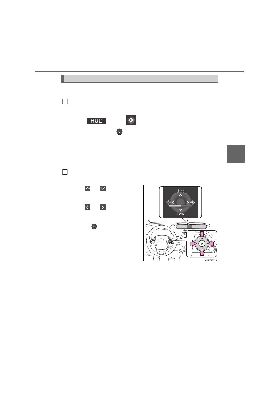
In order to improve the visibility of the head-up display, the display
position and brightness can be adjusted.

Displaying the adjustment screen on the multi-information display.
When the head-up display is on:

Select 

 on the 

 screen of the multi-information dis-

play, and then press 

. (

P. 247)

When the head-up display is off:
When the “HUD” switch is pressed, the adjustment screen for the
head-up display automatically displays.

*

1

If an adjustment operation is not performed for approximately 6 seconds

*

2

,

the multi-information display automatically returns to the previous screen.

Adjusting the display position and brightness by operating the
meter control switches.

When 

 or 

 is pressed, the

position of the head-up display
changes.

When 

 or 

 is pressed, the

brightness of the head-up display
changes.

When the 

 is pressed, the multi-

information display returns to the
previous screen.

*

1

: This function can be turned off. (

P. 250)

*

2

: The adjustment screen may suddenly be canceled if it is interrupted by a

warning message shown on the display.

Display position and brightness adjustment

1

2

258

3. Instrument cluster

Insert displays of the driving support systems

Insert displays are linked with the operation of the following sys-
tems and used to show some of the information shown on the multi-
information display on the head-up display.

*

: If equipped

Master warning light insert display

When the master warning light
(

P. 662) is illuminated or

flashing, an insert display is
shown on the head-up display
to inform the driver.

When the master warning light
is illuminated or flashing, check
the message displayed on the
multi-information display and
perform the corresponding trou-
bleshooting procedure. 
(

P. 667)

Right-hand drive vehicles: 
The master warning light display appears under the vehicle speed dis-
play.

Insert display

System

Displayed information

PCS (Pre-Collision System) (

P. 368)

Pre-collision warning

LTA (Lane Tracing Assist) (

P. 379)

Lane departure alert function
display

Hands off steering wheel warn-
ing

Vehicle sway warning function
display

Dynamic radar cruise control with full-
speed range (

P. 401)

Approach warning display

RSA (Road Sign Assist) (

P. 395)

Road signs, supplemental mark,
etc.

Parking Support Brake function

*


(

P. 462)

Operation display 
(symbol display)

259

3. Instrument cluster

3

In

st

rum

ent cl

ust
e

r

Enabling/disabling of the head-up display

When the head-up display is turned off with the “HUD” switch, it is not dis-
played until the “HUD” switch is used to turn the head-up display on again.
(Operation of the head-up display is not linked with the power switch.)

Display brightness

The brightness of the head-up display is automatically adjusted according to
the operation status of the headlights (on/off) and the brightness of the sur-
roundings.

When the brightness of the head-up display is adjusted to a certain level or
higher, the display automatically dims when the vehicle is stopped. Once the
vehicle starts off and the vehicle speed reaches approximately 5 km/h
(3.1 mph) or more, the display automatically returns to its previous bright-
ness.

Vehicle speed display

In extremely cold environments, the display of the speedometer and the vehi-
cle speed of the head-up display may slightly differ.

Head-up display

The head-up display may seem dark and hard to see when viewed through
sunglasses, especially polarized sunglasses.

When the 12-volt battery is disconnected

The customize settings of the head-up display will be reset.

260

3. Instrument cluster

WARNING

Before using the head-up display

Check that the position and brightness of the head-up display image does
not interfere with safe driving. Incorrect adjustment of the image’s position
or brightness may obstruct the driver’s view and lead to an accident,
resulting in death or serious injury.

Do not continuously look at the head-up display while driving as you may
fail to see pedestrians, objects on the road, etc. ahead of the vehicle.

NOTICE

To prevent damage to components

Do not place any drinks near the head-
up display projector. If the projector gets
wet, electrical malfunctions may result.

Do not place anything on or put stickers
onto the head-up display projector. 
Doing so could interrupt head-up dis-
play indications.

Do not touch the inside of the head-up
display projector or thrust sharp edges
or the like into the projector.
Doing so could cause mechanical mal-
functions.

Display projector

261

3. Instrument cluster

3

In

st

rum

ent cl

ust
e

r

Energy monitor/consumption screen

Navigation system screen
“MENU” button

The energy monitor can be used to check the vehicle drive status,
hybrid system operation status and energy regeneration status.

Display procedure

Press the “MENU” button.
Select “Info” on the “Menu” screen.

If a screen other than “Energy Monitor” is displayed, select
“Energy”.

The state of the hybrid system can be viewed on the navigation
system screen.
The energy monitor and fuel consumption screen can also be
displayed on the multi-information display and home screen of
the navigation system screen.

For information regarding the multi-information display, refer to 
P. 220.

System components

1
2

Energy monitor

1

2

262

3. Instrument cluster

Reading the display

The arrows will appear in accordance with the energy flow. When
there is no energy flow, arrows will not be displayed.
The color of the arrows will change as follows.
Green: When the hybrid battery (traction battery) is regenerated or
charged. 
Yellow: When the hybrid battery (traction battery) is in use. 
Red: When the gasoline engine is in use.

Navigation system screen

Gasoline engine
Electric motor (traction
motor)
Air conditioning system oper-
ation

*

1

Charging connector

*

2

Tires
Hybrid battery (traction bat-
tery)

The image shows all the arrows as an example. The actual display
will vary depending on conditions.

*

1

: The icon is displayed when the air conditioning system is operating.

*

2

: The icon is displayed when charging.

Navigation system screen (Home screen)

Gasoline engine
Hybrid battery (traction bat-
tery)
Tires

The image shows all the arrows as an example. The actual display
will vary depending on conditions.

1
2

3

4
5
6

1
2

3

263

3. Instrument cluster

3

In

st

rum

ent cl

ust
e

r

Remaining charge amount warning of hybrid battery (traction battery)

The buzzer sounds intermittently when the hybrid battery (traction battery)
remains without charging while the shift position is in N, or the remaining
charge amount drops below a certain level. If the remaining charge amount
drops further, the buzzer sounds continuously.

When a warning message is shown on the multi-information display and the
buzzer sounds, follow the instructions displayed on the screen to perform
troubleshooting.

Color of the hybrid battery (traction battery) on the navigation system
screen

It will be green when the hybrid battery (traction battery) is being charged,
and yellow when the hybrid battery (traction battery) is being used.

Color of the gasoline engine on the navigation system screen

It will be blue when the engine is warming up.

264

3. Instrument cluster

Display procedure

Press the “MENU” button.
Select “Info” on the “Menu” screen.

Trip information

If a screen other than “Trip information” is displayed, select “Trip
information”.

Fuel consumption in the past
15 minutes
Regenerated energy in the
past 15 minutes

One 

 symbol indicates 30 Wh.

Up to 5 symbols are shown.

Current fuel consumption
Resetting the consumption
data
Average vehicle speed since the hybrid system was started
Elapsed time since the hybrid system was started
Cruising range

Average fuel consumption for the past 15 minutes is divided by
color into past averages and averages attained since the power
switch was last turned to ON mode. 
Use the displayed average fuel consumption as a reference.
The image is an example only, and may vary slightly from actual
conditions.

Consumption screen

1

2

1

2

3
4

5
6
7

265

3. Instrument cluster

3

In

st

rum

ent cl

ust
e

r

History

If a screen other than “History” is displayed, select “History”.

Best recorded fuel consump-
tion
Latest fuel consumption
Previous fuel consumption
record

Displays the daily average fuel
consumption.

Updating the latest fuel con-
sumption data
Resetting the history data

The average fuel consumption history is divided by color into past
averages and the average fuel consumption since the last updated.
Use the displayed average fuel consumption as a reference.
The image is an example only, and may vary slightly from actual
conditions. 

Updating the history data

Update the latest fuel consumption by selecting “Update” to measure the cur-
rent fuel consumption again.

Resetting the data

The fuel consumption data can be deleted by selecting “Clear”.

Cruising range

Displays the estimated maximum distance that can be driven with the quan-
tity of fuel remaining.
This distance is computed based on your average fuel consumption. As a
result, the actual distance that can be driven may differ from that displayed.

Home screen

The average fuel consumption and distance to empty can be displayed on the
home screen of the navigation system screen.
For details of the home screen, refer to the “Navigation system Owner’s man-
ual”.

1

2
3

4

5

267

4

Operation of

each component

4-1. Key information

Keys...................................268

4-2. Opening, closing and 

locking the doors

Side doors..........................273
Back door...........................278
Smart entry & start 

system .............................283

4-3. Adjusting the seats

Front seats.........................290
Rear seats .........................292
Head restraints ..................294

4-4. Adjusting the steering 

wheel and mirrors

Steering wheel ...................297
Inside rear view mirror .......299
Outside rear view 

mirrors .............................301

4-5. Opening and closing the 

windows

Power windows..................303

268

4-1. Key information

Keys

The following keys are provided with the vehicle.

Electronic keys

• Operating the smart entry &

start system (

P. 283)

• Operating the wireless remote

control function

• Operating the Remote Air Con-

ditioning System (

P. 535)

Mechanical keys
Key number plate

Locks all the doors (

P. 273)

Closes the side windows

*


(

P. 273)

Unlocks all the doors (

P. 273)

Opens the side windows

*


(

P. 273)

Operates Remote Air Condi-
tioning System (

P. 535)

*

: These settings must be customized at any authorized Toyota retailer or

Toyota authorized repairer, or any reliable repairer.

The keys

1

2
3

Wireless remote control

1
2

3
4

5

269

4-1. Key information

4

O

p

er

ati

on 
of e
a

ch

 c

o

m

pon
ent

To take out the mechanical key,
slide the release lever and take
the key out. 

The mechanical key can only be
inserted in one direction, as the
key only has grooves on one side.
If the key cannot be inserted in a
lock cylinder, turn it over and re-
attempt to insert it.
After using the mechanical key, store it in the electronic key. Carry the
mechanical key together with the electronic key. If the electronic key bat-
tery is depleted or the entry function does not operate properly, you will
need the mechanical key. (

P. 695)

If you lose your mechanical keys

New genuine mechanical keys can be made by any authorized Toyota retailer
or Toyota authorized repairer, or any reliable repairer using another mechani-
cal key and the key number stamped on your key number plate. Keep the
plate in a safe place such as your wallet, not in the vehicle.

When riding in an aircraft

When bringing an electronic key onto an aircraft, make sure you do not press
any buttons on the electronic key while inside the aircraft cabin. If you are
carrying an electronic key in your bag etc., ensure that the buttons are not
likely to be pressed accidentally. Pressing a button may cause the electronic
key to emit radio waves that could interfere with the operation of the aircraft. 

Using the mechanical key

Release 
lever

270

4-1. Key information

Electronic key battery depletion

The standard battery life is 1 to 2 years.

If the battery becomes low, an alarm will sound in the cabin and a message
will be displayed on the multi-information display when the hybrid system
stops.

As the electronic key always receives radio waves, the battery will become
depleted even if the electronic key is not used. The following symptoms indi-
cate that the electronic key battery may be depleted. Replace the battery
when necessary. (

P. 632)

• The smart entry & start system or the wireless remote control does not

operate.

• The detection area becomes smaller.
• The LED indicator on the key surface does not turn on.
You can replace the battery by yourself (

P. 632). However, as there is a

danger that the electronic key may be damaged, it is recommended that
replacement is carried out by any authorized Toyota retailer or Toyota
authorized repairer, or any reliable repairer.

To avoid serious deterioration, do not leave the electronic key within 1 m
(3 ft.) of the following electrical appliances that produce a magnetic field:
• TVs
• Personal computers
• Cellular phones, cordless phones and battery chargers
• Table lamps
• Induction cookers

271

4-1. Key information

4

O

p

er

ati

on 
of e
a

ch

 c

o

m

pon
ent

If a message regarding the state of the electronic key or power switch
mode, etc. is shown

To prevent trapping the electronic key inside the vehicle, leaving the vehicle
without turning off the power switch or other passengers from unintentionally
taking the key out of the vehicle, etc., a message that prompts the user to
confirm the state of the electronic key or power switch mode may be shown
on the multi-information display. In those cases, follow the instructions on the
display immediately.

If “Key Battery Low Replace Key Battery” is displayed on the multi-infor-
mation display

The electronic key has a low battery. Replace the electronic key battery. 
(

P. 632)

Replacing the battery

P. 632

Confirmation of the registered key number

The number of keys already registered to the vehicle can be confirmed. Ask
any authorized Toyota retailer or Toyota authorized repairer, or any reliable
repairer.

If “A New Key has been Registered Contact Your Dealer for Details” is
displayed on the multi-information display

This message will be displayed each time the driver’s door is opened when
the doors are unlocked from the outside for approximately 10 days after a
new electronic key has been registered.
If this message is displayed but you have not had a new electronic key regis-
tered, ask any authorized Toyota retailer or Toyota authorized repairer, or any
reliable repairer to check if an unknown electronic key (other than those in
your possession) has been registered.

If a wrong key is used

The key cylinder rotates freely to isolate inside mechanism.

272

4-1. Key information

NOTICE

To prevent key damage

Do not drop the keys, subject them to strong shocks or bend them.

Do not expose the keys to high temperatures for long periods of time.

Do not get the keys wet or wash them in an ultrasonic washer etc.

Do not attach metallic or magnetic materials to the keys or place the keys
close to such materials.

Do not disassemble the keys.

Do not attach a sticker or anything else to the surface of the electronic key.

Do not place the keys near objects that produce magnetic fields, such as
TVs, audio systems and induction cookers.

Do not place the keys near medical electrical equipment such as low-fre-
quency therapy equipment or microwave therapy equipment, and do not
receive medical attention with the keys on your person.

Carrying the electronic key on your person

Carry the electronic key 10 cm (3.9 in.) or more away from electric appli-
ances that are turned on. Radio waves emitted from electric appliances
within 10 cm (3.9 in.) of the electronic key may interfere with the key, caus-
ing the key to not function properly.

In case of a smart entry & start system malfunction or other key-related
problems

Take your vehicle with all the electronic keys provided with your vehicle to
any authorized Toyota retailer or Toyota authorized repairer, or any reliable
repairer.

When an electronic key is lost

If the electronic key remains lost, the risk of vehicle theft increases signifi-
cantly. Visit any authorized Toyota retailer or Toyota authorized repairer, or
any reliable repairer immediately with all remaining electronic keys that
were provided with your vehicle.

273

4-2. Opening, closing and locking the doors

4

O

p

er

ati

on 
of e
a

ch

 c

o

m

pon
ent

Side doors

Smart entry & start system

Carry the electronic key to enable this function.

Grip the front door handle to
unlock all the doors.

Make sure to touch the sensor
on the back of the handle.
The doors cannot be unlocked
for 3 seconds after the doors are
locked.

Touch the lock sensor (the
indentation on the surface of
the front door handle) to lock
the doors.

Check that the door is securely locked.

Wireless remote control

Locks all the doors

Check that the door is securely
locked.
Press and hold to close the side
windows.

*

Unlocks all the doors

Press and hold to open the side
windows.

*

*

: These settings must be customized at any authorized Toyota retailer or

Toyota authorized repairer, or any reliable repairer.

The vehicle can be locked and unlocked using the entry func-
tion, wireless remote control or door lock switches. 

Unlocking and locking the doors from the outside

1

2

1

2


Content      ..     14      15      16      17     ..