Toyota Venza Hybrid (2023 year). Manual in english - page 5
 

  Index      Toyota     Toyota Venza Hybrid (2023 year). Manual in english


Search            copyright infringement  


Content      ..     3      4      5      6     ..


Toyota Venza Hybrid (2023 year). Manual in english - page 5


79

1-4. Hybrid system

1

For
 safety and secu

rity

mize the risk of electrocution 
and fuel leakage. If the emer-
gency shut off system activates, 
your vehicle will not restart. To 
restart the hybrid system, con-
tact your Toyota dealer.

A message is automatically dis-
played when a malfunction 
occurs in the hybrid system or 
an improper operation is 
attempted.
If a warning message is shown 
on the multi-information display, 
read the message and follow the 
instructions.

If a warning light comes on, a 

warning message is displayed, 

or the 12-volt battery is discon-

nected

The hybrid system may not start. In 

this case, try to start the system 

again. If the “READY” indicator does 

not come on, contact your Toyota 

dealer.

Hybrid warning message

80

1-5. Theft deterrent system

1-5.Theft deterrent system

The indicator light flashes after 
the power switch has been 
turned to off to indicate that the 
system is operating.
The indicator light stops flashing 
after the power switch has been 
turned to ACC or ON to indicate 
that the system has been can-
celed.

System maintenance

The vehicle has a maintenance-free 

type immobilizer system.

Conditions that may cause the 

system to malfunction

If the grip portion of the key is in 

contact with a metallic object

If the key is in close proximity to or 

touching a key to the security sys-

tem (key with a built-in transpon-

der chip) of another vehicle

Immobilizer system

The vehicle’s keys have 
built-in transponder chips 
that prevent the hybrid sys-
tem from starting if a key 
has not been previously 
registered in the vehicle’s 
on-board computer.
Never leave the keys inside 
the vehicle when you leave 
the vehicle.

This system is designed to 
help prevent vehicle theft but 
does not guarantee absolute 
security against all vehicle 
thefts.

Operating the system

NOTICE

To ensure the system oper-

ates correctly

Do not modify or remove the sys-

tem. If modified or removed, the 

proper operation of the system 

cannot be guaranteed.

81

1-5. Theft deterrent system

1

For
 safety and secu

rity

Items to check before lock-
ing the vehicle

To prevent unexpected trigger-
ing of the alarm and vehicle 
theft, make sure of the following:

Nobody is in the vehicle.

The side windows are closed 
before the alarm is set.

No valuables or other per-
sonal items are left in the 
vehicle.

Setting

Close the doors, hood, and lock 
all the doors. The system will be 
set automatically after 30 sec-
onds.
The security indicator changes 

from being on to flashing when 
the system is set.
If all doors are closed with hood 
open, alarm system can be set.

Canceling or stopping

Do one of the following to deac-
tivate or stop the alarm:

Unlock the doors using the 
entry function or wireless 
remote control.

Turn the power switch to ACC 
or ON, or start the hybrid sys-
tem. (The alarm will be deacti-
vated or stopped after a few 
seconds.)

System maintenance

The vehicle has a maintenance-free 

type alarm system.

Triggering of the alarm

The alarm may be triggered in the 

following situations:

(Stopping the alarm deactivates the 

alarm system.)
The doors are unlocked using the 

mechanical key.

Alarm

The alarm uses light and 
sound to give an alert when 
an intrusion is detected.
The alarm is triggered in the 
following situations when 
the alarm is set:

A locked door is unlocked or 
opened in any way other 
than using the entry func-
tion or wireless remote con-
trol. (The doors will lock 
again automatically.)

The hood is opened.

Setting/canceling/stop-
ping the alarm system

82

1-5. Theft deterrent system

If a door is unlocked using the 

mechanical key while the alarm is 

set, a warning will sound intermit-

tently for approximately 10 seconds. 

If the alarm is not canceled or 

stopped during this time, the warn-

ing pattern changes and the warn-

ing sounds for a certain period of 

time.

A person inside the vehicle opens 

a door or hood, or unlocks the 

vehicle using an inside lock but-

ton.

The 12-volt battery is recharged or 

replaced when the vehicle is 

locked. (

P.468)

Alarm-operated door lock

In the following cases, depending 

on the situation, the door may auto-

matically lock to prevent improper 

entry into the vehicle:

When a person remaining in the 

vehicle unlocks the door and the 

alarm is activated.

While the alarm is activated, a 

person remaining in the vehicle 

unlocks the door.

When recharging or replacing the 

12-volt battery.

NOTICE

To ensure the system oper-

ates correctly

Do not modify or remove the sys-

tem. If modified or removed, the 

proper operation of the system 

cannot be guaranteed.

83

2

2

Vehicle

 statu

s information an

d in
dicator

s

Vehicle status informa-

tion and indicators

2-1. Instrument cluster

Warning lights and indica-

tors ...............................

84

Gauges and meters (Vehi-

cles with 7-inch multi-infor-
mation display) .............

90

Gauges and meters (Vehi-

cles with 12.3-inch multi-
information display) ......

94

Multi-information display (7-

inch multi-information dis-
play) ..........................

100

Multi-information display 

(12.3-inch multi-informa-
tion display) ...............

111

Head-up display ..........

123

Energy monitor/consump-

tion screen.................

128

84

2-1. Instrument cluster

2-1.Instrument cluster

For the purpose of explanation, the following illustrations display all 
warning lights and indicators illuminated.

Vehicles with 7-inch multi-information display

The units used on the meters and some indicators may differ depending on 
the target region.

Warning lights and indicators

The warning lights and indicators on the instrument cluster, 
overhead console panel and outside rear view mirrors inform 
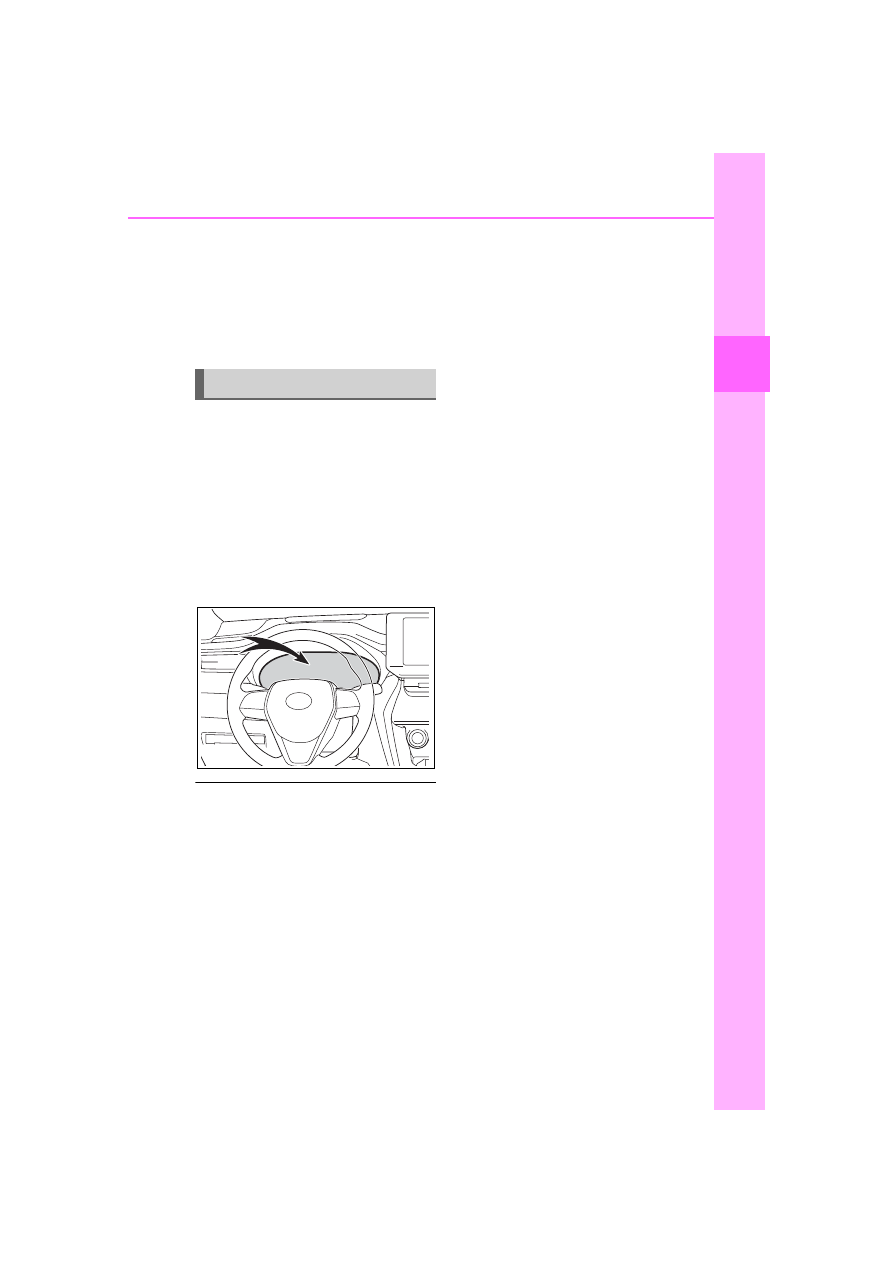
the driver of the status of the vehicle’s various systems.

Instrument cluster

85

2-1. Instrument cluster

2

Vehicle

 statu

s information an

d in
dicator

s

Vehicles with 12.3-inch multi-information display

Type 1

The units used on the meters and some indicators may differ depending on 
the target region.

Type 2

The units used on the meters and some indicators may differ depending on 
the target region.

86

2-1. Instrument cluster

Type 3

The units used on the meters and some indicators may differ depending on 
the target region.

Warning lights inform the driver 
of malfunctions in the indicated 
vehicle’s systems.

Warning lights

(U.S.A.)

Brake system warning 
light

*1

 (

P.441)

(Canada)

(Red)

Brake system warning 
light

*1

 (

P.441)

(Yellow)

Brake system warning 
light

*1

 (

P.441)

Charging system warning 
light

*2

 (

P.441)

High coolant temperature 
warning light

*2

 (

P.442)

Low engine oil pressure 
warning light

*2

 (

P.442)

(U.S.A.)

Malfunction indicator 
lamp

*1

 (

P.442)

(Canada)

Malfunction indicator 
lamp

*1

 (

P.442)

SRS warning light

*1


(

P.442)

(U.S.A.)

ABS warning light

*1


(

P.443)

(Canada)

ABS warning light

*1


(

P.443)

(Red)

Electric power steering 
system warning light

*1


(

P.443)

(Yellow)

Electric power steering 
system warning light

*1


(

P.443)

87

2-1. Instrument cluster

2

Vehicle

 s

ta

tu

s information an

d in
dicat

or

s

*1

:These lights turn on when the 

power switch is turned to ON to 
indicate that a system check is 
being performed. They will turn 
off after the hybrid system is on, 
or after a few seconds. There 
may be a malfunction in a sys-
tem if the light does not come on, 
or turn off. Have the vehicle 
inspected by your Toyota dealer.

*2

:This light illuminates on the 

multi-information display with a 
message.

*3

:Intuitive parking assist OFF indi-

cator turns on when the power 
switch is turned to ON while the 
Intuitive parking assist function is 
on. It will turn off after a few sec-
onds.

(Flashes 

or illumi-

nates)

PCS warning light

*1


(

P.443)

(Orange)

LTA indicator (

P.444)

Intuitive parking assist 
OFF indicator

*3

 (if 

equipped) (

P.444)

PKSB OFF indicator

*1

 (if 

equipped) (

P.444)

RCTA OFF indicator

*1


(

P.445)

Slip indicator light

*1


(

P.445)

Inappropriate pedal opera-
tion warning light

*2


(

P.445)

(Flashes)

Brake hold operated indi-
cator

*1

 (

P.446)

(U.S.A.)

(Flashes)

Parking brake indicator 
(

P.446)

(Canada)
(Flashes)

Parking brake indicator 
(

P.446)

Tire pressure warning 
light

*1

 (

P.446)

Low fuel level warning 
light (

P.446)

Driver’s and front passen-
ger’s seat belt reminder 
light (

P.447)

Rear 

passengers’

seat  belt  reminder
light (

P.447)

WARNING

If a safety system warning 

light does not come on

Should a safety system light such 

as the ABS and SRS warning light 

not come on when you start the 

hybrid system, this could mean 

that these systems are not avail-

able to help protect you in an acci-

dent, which could result in death 

or serious injury. Have the vehicle 

inspected by your Toyota dealer 

immediately if this occurs.

88

2-1. Instrument cluster

The indicators inform the driver 
of the operating state of the 
vehicle’s various systems.

Indicators

Turn signal indicator 
(

P.212)

(U.S.A.)

Headlight indicator 
(

P.219)

(Canada)

Tail light indicator 
(

P.219)

Headlight high beam indi-
cator (

P.221)

Automatic High Beam indi-
cator (

P.222)

Fog light indicator (if 
equipped) (

P.225)

Smart key system indica-
tor

*1

 (

P.201)

Cruise control indicator 
(

P.265)

Dynamic radar cruise con-
trol indicator (

P.265)

Cruise control “SET” indi-
cator (

P.265)

(White)

LTA indicator

*2

 (

P.256)

(Green)

LTA indicator

*2

 (

P.239, 

256)

(Orange)

(Flashes)

LTA indicator

*2

 (

P.256)

Intuitive parking assist 
OFF indicator

*3, 4

 (if 

equipped) (

P.288)

PKSB OFF indicator

*3, 5

 (if 

equipped) (

P.296)

(Flashes)

Slip indicator light

*5


(

P.306)

VSC OFF indicator

*3, 5


(

P.307)

PCS warning light

*3, 5


(

P.239)

BSM outside rear view 
mirror indicators

*5, 6


(

P.278)

BSM OFF indicator

*3, 5


(

P.278)

RCTA OFF indicator

*3, 5


(

P.278)

Brake hold standby indica-
tor

*5

 (

P.217)

Brake hold operated indi-
cator

*5

 (

P.217)

Security indicator

*7


(

P.80, 81)

“READY” indicator 
(

P.201)

Low outside temperature 
indicator

*8

 (

P.98, 91)

EV indicator (

P.71)

(U.S.A.)

Parking brake indicator 
(

P.213)

(Canada)

Parking brake indicator 
(

P.213)

89

2-1. Instrument cluster

2

Vehicle

 statu

s information an

d in
dicator

s

*1

:This light illuminates on the 

multi-information display with a 
message.

*2

:Depending on the operating con-

dition, the color and illuminat-
ing/flashing state of the light 
change.

*3

:The light comes on when the 

system is turned off.

*4

:Intuitive parking assist OFF indi-

cator turns on when the power 
switch is turned to ON while the 
Intuitive parking assist function is 
on. It will turn off after a few sec-
onds.

*5

:These lights turn on when the 

power switch is turned to ON to 
indicate that a system check is 
being performed. They will turn 
off after the hybrid system is on, 
or after a few seconds. There 
may be a malfunction in a sys-
tem if the lights do not turn on, or 
turn off. Have the vehicle 
inspected by your Toyota dealer.

*6

:This light illuminates on the out-

side rear view mirrors.

*7

:This light illuminates on the over-

head console panel.

*8

:When the outside temperature is 

approximately 37°F (3°C) or 
lower, the indicator will flash for 

approximately 10 seconds, then 
stay on.

BSM (Blind Spot Monitor) out-

side rear view mirror indicators

In order to confirm operation, the 

BSM outside rear view mirror indica-

tors illuminate in the turning the 

BSM function/RCTA function on 

(

P.278).

If the system is functioning correctly, 

the BSM outside rear view mirror 

indicators will turn off after a few 

seconds.
If the BSM outside rear view mirror 

indicators do not illuminate or do not 

turn off, there may be a malfunction 

in the system. If this occurs, have 

the vehicle inspected by your 

Toyota dealer.

EV drive mode indicator 
(

P.206)

Eco drive mode indicator 
(

P.304)

Sport mode indicator 
(

P.304)

“AIR BAG ON/OFF” 
indicator

*5, 7

 (

P.43)

90

2-1. Instrument cluster

The units used on the meter and display may differ depending on the target 
region.

Hybrid System Indicator

Displays hybrid system output or regeneration level (

P.91)

Multi-information display

Presents the driver with a variety of driving-related data (

P.111)

Displays warning messages if a malfunction occurs (

P.451)

Clock

The GPS clock’s time is automatically adjusted by utilizing GPS time infor-
mation.
For details, refer to the “MULTIMEDIA OWNER’S MANUAL”.

Speedometer

Displays the vehicle speed

Fuel gauge

Displays the quantity of fuel remaining in the tank

Odometer, trip meter and oil maintenance

Odometer:
Displays the total distance that the vehicle has been driven

Gauges and meters (Vehicles with 7-inch multi-

information display)

The meters display various drive information.

Meter display

A

B

C

D

E

F

91

2-1. Instrument cluster

2

Vehicle

 statu

s information an

d in
dicator

s

Trip meter:
Displays the distance the vehicle has been driven since the meter was last 
reset. Trip meters “A” and “B” can be used to record and display different 
distances independently.
Oil maintenance:
Displays the distance until the next engine oil change.

Shift position and shift range indicator

Displays the selected shift position or selected shift range (

P.208)

Outside temperature (

P.91)

Engine coolant temperature gauge

Displays the engine coolant temperature

The meters and display illumi-

nate when

The power switch is in ON.

Hybrid System Indicator

READY OFF area

Shows that the hybrid system is not 
operating.

Charge area

Shows regeneration

*

 status. Regen-

erated energy will be used to charge 
the hybrid battery (traction battery).

Hybrid Eco area

Shows that gasoline engine power 
is not being used very often.

The gasoline engine will automati-
cally stop and restart under various 
conditions.

Eco area

Shows that the vehicle is being 
driven in an Eco-friendly manner.
By keeping the indicator needle 
within Eco area, more Eco-friendly 
driving can be achieved.

Power area

Shows that an Eco-friendly driving 

G

H

I

A

B

C

D

E

92

2-1. Instrument cluster

range is being exceeded (during full 
power driving etc.)

*

: When used in this manual, “regen-

eration” refers to the conversion of 
energy created by the movement 
of the vehicle into electrical 
energy.

In the following situation, the Hybrid 

System Indicator does not operate.

“READY” indicator is not illumi-

nated.

The shift position is in a range 

other than D or S.

Outside temperature display

In the following situations, the cor-

rect outside temperature may not 

be displayed, or the display may 

take longer than normal to 

change.

• When stopped, or driving at low 

speeds (less than 12 mph [20 

km/h])

• When the outside temperature 

has changed suddenly (at the 

entrance/exit of a garage, tunnel, 

etc.)

When “--” or “E” is displayed, the 

system may be malfunctioning.

Take your vehicle to your Toyota 

dealer.

Displays the outside temperature 

within the range of -40°F (-40°C) 

to 122°F (50°C).

When the outside temperature is 
approximately 37°F (3°C) or 
lower, the indicator 

 will flash 

for approximately 10 seconds, 
then stay on.

Liquid crystal display

P.101

Display items

Odometer

Displays the total distance the vehi-
cle has been driven.

Trip meter A/trip meter B

Displays the distance the vehicle 
has been driven since the meter 
was last reset. Trip meters A and B 
can be used to record and display 
different distances independently. 

WARNING

The information display at 

low temperatures

Allow the interior of the vehicle to 

warm up before using the liquid 

crystal information display. At 

extremely low temperatures, the 

display monitor may respond 

slowly, and display changes may 

be delayed.
For example, there is a lag 

between the driver’s shifting and 

the new shift range appearing on 

the display. This lag could cause 

the driver to downshift again, 

causing rapid and excessive 

engine braking and possibly an 

accident resulting in death or 

injury.

NOTICE

To prevent damage to the 

engine and its components

The engine may be overheating if 

the engine coolant temperature 

gauge is in the red zone (“H”). In 

this case, immediately stop the 

vehicle in a safe place, and check 

the engine after it has cooled 

completely. (

P.473)

Using the “ODO TRIP” 
switch

93

2-1. Instrument cluster

2

Vehicle

 statu

s information an

d in
dicator

s

When the trip meter is displayed, 
pressing and holding the switch will 
reset the trip meter.

Distance until next engine oil 
change

Displays the distance the vehicle 
can be driven until an oil change is 
necessary.

Changing the display

Each time the “ODO TRIP” 
switch is pressed, the displayed 
item will be changed. 
When the trip meter is dis-
played, pressing and holding the 
switch will reset the trip meter.

Pop-up display

Distance until the next engine oil 
change will be displayed when a 
warning message indicating that 
oil maintenance is required or 
should be performed soon is 
displayed.

The brightness of the instrument 
panel lights can be adjusted.

1

Brighter

2

Darker

Instrument cluster brightness 

adjustment

The instrument cluster brightness 

levels when the tail lights are on and 

off can be adjusted individually. 

However, when the surroundings 

are bright (daytime, etc.), turning on 

the tail lights will not change the 

instrument cluster brightness.

Changing the instrument 
panel light brightness

94

2-1. Instrument cluster

The meter display type setting can be changed. (

P.117)

Type 1/Type 2

The location of some displayed items and the units of measure may differ 
depending on the intended destination of the vehicle.

Multi-information display

Presents the driver with a variety of vehicle data (

P.111) 

Displays warning messages if a malfunction occurs (

P.441)

Outside temperature (

P.98)

Analog meter (Type2)

The dial type of analog meter can be changed on 

 of the multi-informa-

tion display. (

P.117) 

Analog speedometer: 
Displays the vehicle speed 
Hybrid System Indicator: 
Displays hybrid system output or regeneration level (

P.97)

Digital speedometer

Displays the vehicle speed

Shift position and shift range (

P.210)

Gauges and meters (Vehicles with 12.3-inch 

multi-information display)

The meters display various drive information.

Meter display

A

B

C

D

E


Content      ..     3      4      5      6     ..