Toyota Tundra (2023 year). Manual in english - page 22
 

  Index      Toyota     Toyota Tundra (2023 year). Manual in english


Search            copyright infringement  


Content      ..     20      21      22      23     ..


Toyota Tundra (2023 year). Manual in english - page 22


351

4-5. Using the driving support systems

4

Dr

iv

ing

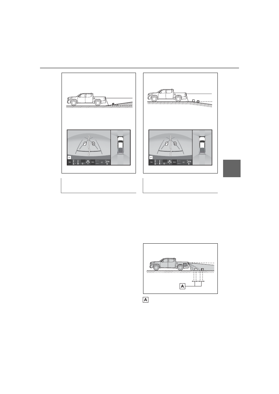
The distance guidelines are pro-
jected on a horizontal surface, 
distances on an downward slop-
ing surface appear closer to the 
vehicle than the actual distance. 
Because of this, objects will 
appear to be closer than they 
actually are. In the same way, 
there will be a margin of error 
between the guidelines and the 
actual distance/course on the 
road.

When the vehicle posture tilts 
due to the number of passen-
gers or the distribution of the 
load, there is a margin of error 
between the guide lines on the 
screen and the actual dis-
tance/course on the road.

A margin of error

When the ground behind the 
vehicle slopes down sharply

When any part of the vehicle 
sags

352

4-5. Using the driving support systems

When there are three-dimensional objects (such as vehicle bum-
pers, etc.) nearby in positions higher than the surface of the road, 
take extra care when using the following.

Since the panoramic view processes and displays images based on 
flat road surfaces, it cannot depict the position of three-dimension 
objects (such as vehicle bumpers, etc.) that are in positions higher 
than the surface of the road. For example, even though it appears 
that there is space between the bumpers of the two vehicles in the 
illustration below and they are not likely to collide, in reality, a colli-
sion is about to occur.

The estimated course lines target flat surfaced objects (such as the 
road). It is not possible to determine the position of three-dimen-
sional objects (such as vehicles) using the estimated course lines 
and distance guide lines. When approaching a three-dimensional 
object that extends outward (such as the flatbed of a truck), be care-

Distortion of three-dimensional objects on the screen

Panoramic view display (including magnified display)

WARNING

When a sensor indicator on the intuitive parking assist display illumi-

nates in red or a buzzer sounds continuously, be sure to check the area 

around the vehicle immediately and do not proceed any further until 

safety has been ensured, otherwise an unexpected accident may occur.

When approaching three-dimensional objects

353

4-5. Using the driving support systems

4

Dr

iv

ing

ful of the following.

Since the estimated course line 
is displayed for a flat road sur-
face, it cannot depict the posi-
tion of three-dimensional objects 
(such as vehicle bumpers, etc.) 
that are in positions higher than 
the surface of the road. Even if 
the bumpers of the vehicle is on 
the outside of the estimated 
course line in the image, in real-
ity, the vehicles are on a colli-
sion course.

Estimated course line

Three-dimensional objects 

(such as the overhang of a wall 
or loading platform of a truck) in 
high positions may not be pro-
jected on the screen. Check the 
safety of the surroundings 
directly.

The pillar that is diagonal to the 
parking spot may be displayed 
perpendicular on the screen. 
Even if it seems like there will 
not be a collision, the pillar is 
diagonal, so there may be colli-
sion with the upper part of the 
pillar.
Check the safety of the sur-
roundings directly.

WARNING

When a sensor indicator on the intuitive parking assist display illumi-

nates in red or a buzzer sounds continuously, be sure to check the area 

around the vehicle immediately and do not proceed any further until 

safety has been ensured, otherwise an unexpected accident may occur.

Estimated course lines

354

4-5. Using the driving support systems

Visually check the surroundings 
and the area behind the vehicle. 
In the case shown below, the 
truck appears to be outside of 
the estimated course lines and 
the vehicle does not look as if it 
hits the truck. However, the rear 
body of the truck may actually 
cross over the estimated course 
lines. In reality if you back up as 
guided by the estimated course 
lines, the vehicle may hit the 
truck.

Estimated course lines

Visually check the surroundings 
and the area behind the vehicle. 
On the screen, it appears that a 
truck is parking at point  . 
However, in reality if you back 
up to point  , you will hit the 
truck. On the screen, it appears 
that   is closest and   is far-
thest away. However, in reality, 
the distance to   and   is the 
same, and   is farther than   
and  .

Distance guide lines

355

4-5. Using the driving support systems

4

Dr

iv

ing

If you notice any of the following symptoms, refer to the likely cause 
and the solution, and re-check.
If the symptom is not resolved by the solution, have the vehicle 
inspected by your Toyota dealer.

Things you should know

If you notice any symptoms

356

4-5. Using the driving support systems

Symptom

Likely cause

Solution

The image is difficult to 
see

The vehicle is in a 
dark area

The temperature 
around the lens is 
either high or low

The outside tempera-
ture is low

There are water drop-
lets on the camera

It is raining or humid

Foreign matter (mud, 
etc.) is adhering to the 
camera

Sunlight or headlights 
are shining directly 
into the camera

The vehicle is under 
fluorescent lights, 
sodium lights, mer-
cury lights, etc.

Back up while visually 
checking the vehicle’s 
surroundings. (Use the 
monitor again once con-
ditions have been 
improved.)
The procedure for 
adjusting the picture 
quality of the pan-
oramic view monitor 
system is the same as 
the procedure for 
adjusting the screen dis-
play. (Refer to the 
“MULTIMEDIA 
OWNER’S MANUAL”.)

The image is blurry

Dirt or foreign matter 
(such as water drop-
lets, snow, mud, etc.) is 
adhering to the camera.

Flush the camera with a 
large quantity of water 
and wipe the camera 
lens clean with a soft 
and wet cloth.

The image is out of 
alignment

The camera or sur-
rounding area has 
received a strong 
impact.

Have the vehicle 
inspected by your Toy-
ota dealer.

The guide lines are very 
far out of alignment

The camera position is 
out of alignment.

Have the vehicle 
inspected by your Toy-
ota dealer.

The vehicle is tilted. 
(There is a heavy load 
on the vehicle, tire 
pressure is low due to 
a tire puncture, etc.)

The vehicle is used on 
an incline.

If this happens due to 
these causes, it does 
not indicate a malfunc-
tion.
Back up while visually 
checking the vehicle’s 
surroundings.

357

4-5. Using the driving support systems

4

Dr

iv

ing

The estimated course 
lines move even though 
the steering wheel is 
straight

There is a malfunction 
in the signals being out-
put by the steering sen-
sor.

Have the vehicle 
inspected by your Toy-
ota dealer.

Guide lines are not dis-
played

The tailgate is open.

Close the tailgate.
If this does not resolve 
the symptom, have the 
vehicle inspected by 
your Toyota dealer.

 is displayed

Battery has been rein-
stalled.

The steering wheel 
has been moved while 
the battery was being 
reinstalled.

Battery power is low.

The steering sensor 
has been reinstalled.

There is a malfunction 
in the signals being 
output by the steering 
sensor.

Have the vehicle 
inspected by your Toy-
ota dealer.

The panoramic view dis-
play cannot be magni-
fied

The intuitive parking 
assist may be malfunc-
tioning or dirty.

Follow the correction 
procedures for malfunc-
tions of the intuitive 
parking assist. (

P.289)

The see-through 
view/moving view can-
not be displayed

Symptom

Likely cause

Solution

358

4-5. Using the driving support systems

*

: If equipped

The camera switch is located as 
shown in the illustration.

The Multi-terrain Monitor is dis-
played by operating 

 when 

vehicle speed is approximately 10 
mph (16 km/h) or less. If the vehi-
cle speed exceeds approximately 
10 mph (16 km/h), the Multi-ter-
rain Monitor display is canceled.

Multi-terrain Monitor

*

The Multi-terrain Monitor 
helps the driver to check the 
vehicle surroundings. It 
assists in determining the 
conditions around the 
driver in a variety of situa-
tions, such as when judging 
conditions during off-road 
driving or checking for 
obstacles when parking.

WARNING

Observe the following precautions 

to avoid an accident that could 

result in death or serious injuries.

When using the Multi-terrain 

Monitor system

Never rely solely on the Multi-

terrain Monitor. As with 

unequipped vehicles, drive 

carefully while directly confirm-

ing the safety of your surround-

ings and the area to the rear of 

the vehicle. Take particular care 

to avoid parked cars and other 

obstacles.

Due to the characteristics of the 

camera lens, the actual position 

and distance of people and 

other obstacles will differ from 

those shown on the Multi-terrain 

Monitor screen. Directly con-

firm the safety of your surround-

ings before driving.

Do not drive while only looking 

at the screen. When driving, 

make sure to directly confirm 

the safety of your surroundings, 

such as by visually checking the 

area and using the vehicle’s 

mirrors.

In low temperatures, the screen 

may darken or the images may 

become faint. Images of moving 

objects in particular may distort 

or disappear from the screen. 

Therefore, make sure to drive 

carefully while directly visually 

confirming the safety of your 

surroundings.

Camera switch

359

4-5. Using the driving support systems

4

Dr

iv

ing

The screens that are displayed can be selected by the following but-
tons.

Front view & dual side view

Under vehicle terrain view & dual side view

Rear view & dual side view

Wide rear view

Auto mode on/off button (

P.363)

Multi-terrain Monitor on/off button

Panoramic View Monitor is displayed when the Multi-terrain Monitor is 
turned OFF. (

P.325)

The Multi-terrain Monitor is dis-
play a screen suitable for off-
road.

The driver can drive while 
confirming the following 
guidelines with a front view

• Distance with the obstacle in the 

front

• Estimated course line

The driver can drive while 

confirming the obstacle in the 
flank of tire neighborhood and 
the vehicle with a side screen

Front view & dual side view

Select the front view & dual side 
view button.

Menu button

When the front-wheel 
drive control switch is in 
“4L”, or “4H” and Multi-
terrain select is ON

Checking the area to the 
front and sides of the vehi-
cle

360

4-5. Using the driving support systems

When the front view and side view 
screens are touched, each of the 
display sizes can be changed.

Under vehicle terrain view & 
dual side view

Select the under vehicle terrain 
view & dual side view button.

Under vehicle terrain view & 
dual side view (front magni-
fied)

When the under vehicle terrain 
view and side view screens are 
touched, each of the display sizes 
can be changed.

Rear view & dual side view

Select the rear view & dual side 
view button.

Wide rear view

Select the wide rear view button.

Checking the condition of 
the road surface under the 
vehicle

Checking the area to the 
rear of the vehicle

361

4-5. Using the driving support systems

4

Dr

iv

ing

The rear view & dual side view 
and the wide rear displays can 
be switched by touching the 
screen.

The panoramic view monitor is 
displayed. (

P.325)

When automatic display mode is 
turned on, the Multi-terrain Mon-
itor screen is displayed in the 
following conditions, even if 


has not been operated.

• When the shift lever is shifted 

to D or N.

• When vehicle speed is 

reduced to approximately 10 
mph (16 km/h) or less.

The automatic display mode 
switches between on and off each 
time 

 is selected. When auto-

matic display mode is on, an indi-
cator illuminates on the icon.

Even when automatic display 
mode is on, the display can still be 
switched by pressing 

.

The front-wheel drive control switch in the case of “4L”, or “4H” and 
Multi-terrain select is ON, the Multi-terrain Monitor can display a 
screen suitable for off-road.

Front view & dual side view can be used to check the area around 
the front of the vehicle.

In addition to an image of the front of the vehicle, guide lines are 
displayed in a composite view to provide reference for when 
deciding a direction to move forward in.

If the steering wheel is turned 270° or more, guide lines and other 
features to support turning are automatically displayed.

When the front-wheel 
drive control switch is in 
“2H”, or “4H” and Multi-
terrain select is OFF

Automatic display mode

Screen display and functions

Front view & dual side view

362

4-5. Using the driving support systems

Front view & dual side view button

Under vehicle terrain view & dual side view button (

P.366)

Clinometer/slip display

Displays the vehicle’s estimated degree of incline or indicates a tire slip-
page. (

P.365, 366)

Automatic display button

Select to turn automatic display mode on/off. (

P.363)

Vehicle width lines (blue)

Shows guide lines of the vehicle’s width including the outside rear view mir-
rors.

1.5 ft. (0.5 m) distance guide line (red)

Show distance in front of the vehicle.
• Display points approximately 1.5 ft. (0.5 m) from the edge of the bumper.

3 ft. (1 m) distance guide line (blue)

6 ft. (2 m) distance guide line (blue)

Front tire course line (yellow)

Shows the estimated course of the front tires according to steering wheel 
position.

Forward movement guide line (blue)

Shows the estimated tire course of the tightest possible turn.

Front tire contact line (blue)

Shows guide lines of where the front tire touches the ground.

363

4-5. Using the driving support systems

4

Dr

iv

ing

Rear tire contact line (blue)

Shows guide lines of where the rear tire touches the ground.

Rear tire course line (yellow)

Shows the estimated course of the rear tires.

When the steering wheel is turned by 270° or more

Intuitive parking assist

When a sensor detects an obstacle, the direction of and the approximate 
distance to the obstacle are displayed and the buzzer sounds.

The screen can be displayed when the shift lever is in a position other 

than R.

When the intuitive parking assist detects an obstacle or another vehicle, a 

warning message pops up in the clinometer/slip display area.

Clinometer displays the vehicle inclination to the front, rear, left and 
right within a range of 0° to approximately 30°.

Degree markers of incline to the front and rear

Indicates the vehicle inclination in degrees in the front and rear directions.

Degree markers of incline to the left and right

Indicates the vehicle inclination in degrees in the left and right directions.

Pointer

Indicates the degree of the vehicle inclination in comparison to a parallel 
line.

The display indicates the incline of the vehicle in degrees shown by the 

movement of the pointer and the rotation of the vehicle image.

The color of the degree markers of incline to the front, rear, left and right 

changes according to the current incline of the vehicle.

Clinometer

364

4-5. Using the driving support systems

After the engine switch is in ON, the degree of incline is not displayed until 

such information is determined.

The degree of incline showed on the clinometer is only an approximate 

indication, and may differ from the degree of incline measured using other 

equipment.

When tire slippage is detected, 
the clinometer display area is 
automatically switched to the 
slip display.

Tire display

Indicates the position of freely spin-
ning tires in yellow if the tire spins. 
(During Crawl Control is operating, 
all of the tires are indicated in yel-
low.)

Pop-up display of the intuitive 
parking assist

Displayed if an obstacle is detected 
while the intuitive parking assist is 
turned on.

Lines indicating current vehicle and tire position are displayed in a 
composite view on an image taken approximately 32 ft. (10 m) 
behind the current vehicle position and assists the driver to check 
conditions underneath the vehicle or determine the position of the 
front tires.

Current vehicle position

Image displayed in the under vehicle terrain view (image taken 
approximately 32 ft. (10 m) behind the current vehicle position)

Slip display

Under vehicle terrain view & dual side view

365

4-5. Using the driving support systems

4

Dr

iv

ing

Vehicle position at the time the image was taken (approximately 
32 ft. (10 m) behind the current vehicle position)

Under vehicle terrain view & dual side view

Under vehicle terrain view & dual side view (front magnified)

Front view & dual side view button (

P.363)

Under vehicle terrain view & dual side view button

Clinometer/slip display

Displays the vehicle’s estimated degree of incline or indicates a tire slip-
page. (

P.365, 366)

Automatic display button

Select to turn automatic display mode on/off. (

P.363)

Tire position indicator lines (black or white)

Indicates the estimated position of the front tires.

Vehicle position indicator lines (blue)

Indicates the estimated position of the vehicle.

1.5 ft. (0.5 m) distance guide line (red or black)

Displaying the under vehicle terrain view

366

4-5. Using the driving support systems

Show distance in front of the vehicle.
• Display points approximately 1.5 ft. (0.5 m) from the edge of the bumper.

Front tire contact line (blue)

Shows guide lines of where the front tire touches the ground.

Vehicle width lines (blue)

Shows guide lines of the vehicle’s width including the outside rear view mir-
rors.

Rear tire contact line (blue)

Shows guide lines of where the rear tire touches the ground.

Intuitive parking assist

When a sensor detects an obstacle, the direction of and the approximate 
distance to the obstacle are displayed and the buzzer sounds.

The screen can be displayed when the shift lever is in a position other 

than R.

While the under vehicle terrain view is displayed, if the vehicle speed 

reaches or exceeds approximately 3 mph (5 km/h), the screen automati-

cally returns to the front view display.

In the following situations, the under vehicle terrain view selection button 

cannot be operated.

• The vehicle is not completely stopped

• After the engine starts, a fixed distance or more has not been driven

• After the front-wheel drive control switch is shifted to “4L”, a fixed distance 

or more has not been driven

In the following situations, the system may not operate normally, or it may 

not be possible to switch to the under vehicle terrain view.

• The road is covered with snow

• It is nighttime and the road has no illumination

• Dirt or foreign matter is adhering to the camera lens

• There is water in front of the vehicle (a river, puddle, sea water, etc.)

WARNING

The tire position indicator lines and vehicle position indicator lines may 

differ from actual vehicle positions depending on the number of passen-

gers, cargo weight, road grade, road surface conditions, brightness of 

the surrounding environment, etc. Always drive the vehicle while con-

firming the safety of your surroundings.

The image displayed is one that was previously taken at a point approx-

imately 32 ft. (10 m) behind the current vehicle position. In cases such 

as when objects move after the image is taken, the image displayed on 

the screen may differ from the actual state.


Content      ..     20      21      22      23     ..