Toyota Sienna Hybrid (2023 year). Manual in english - page 33
 

  Index      Toyota     Toyota Sienna Hybrid (2023 year). Manual in english


Search            copyright infringement  


Content      ..     31      32      33      34     ..


Toyota Sienna Hybrid (2023 year). Manual in english - page 33


530

8-1. Specifications

Type B

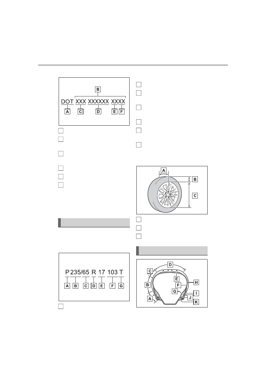
DOT symbol

*

Tire Identification Number 
(TIN)

Tire manufacturer’s identifi-
cation mark

Manufacturer’s code

Manufacturing week

Manufacturing year

*

: The DOT symbol certifies that the 

tire conforms to applicable Fed-
eral Motor Vehicle Safety Stan-
dards.

Typical tire size information

The illustration indicates typical 
tire size.

Tire use 

(P = Passenger car, 
T = Temporary use)

Section width (millimeters)

Aspect ratio
(tire height to section width)

Tire construction code
(R = Radial, D = Diagonal)

Wheel diameter (inches)

Load index (2 digits or 3 dig-
its)

Speed symbol (alphabet with 
one letter)

Tire dimensions

Section width

Tire height

Wheel diameter

Tire size

A

B

C

D

E

F

A

Tire section names

B

C

D

E

F

G

A

B

C

531

8-1. Specifications

8

Vehicle

 specifications

Bead

Sidewall

Shoulder

Tread

Belt

Inner liner

Reinforcing rubber

Carcass

Rim lines

Bead wires

Chafer

This information has been pre-
pared in accordance with regu-
lations issued by the National 
Highway Traffic Safety Adminis-
tration of the U.S. Department of 
Transportation.
It provides the purchasers 
and/or prospective purchasers 
of Toyota vehicles with informa-
tion on uniform tire quality grad-
ing.

Your Toyota dealer will help answer 
any questions you may have as you 
read this information.

DOT quality grades

All passenger vehicle tires must 
conform to Federal Safety 
Requirements in addition to 
these grades. Quality grades 
can be found where applicable 

on the tire sidewall between 
tread shoulder and maximum 
section width.

For example: Treadwear 200 Trac-
tion AA Temperature A

Treadwear

The treadwear grade is a com-
parative rating based on the 
wear rate of the tire when tested 
under controlled conditions on a 
specified government test 
course.

For example, a tire graded 150 
would wear one and a half (1 - 1/2) 
times as well on the government 
course as a tire graded 100.
The relative performance of tires 
depends upon the actual conditions 
of their use. Performance may dif-
fer significantly from the norm due 
to variations in driving habits, ser-
vice practices and differences in 
road characteristics and climate.

Traction AA, A, B, C

The traction grades, from high-
est to lowest, are AA, A, B and 
C, and they represent the tire’s 
ability to stop on wet pavement 
as measured under controlled 
conditions on specified govern-
ment test surfaces of asphalt 
and concrete.

A tire marked C may have poor 
traction performance.
Warning: The traction grade 
assigned to this tire is based on 
braking (straight ahead) traction 
tests and does not include corner-
ing (turning) traction.

Uniform Tire Quality 
Grading

A

B

C

D

E

F

G

H

I

J

K

532

8-1. Specifications

Temperature A, B, C

The temperature grades are A 
(the highest), B, and C, repre-
senting the tire’s resistance to 
the generation of heat and its 
ability to dissipate heat when 
tested under controlled condi-
tions on a specified indoor labo-
ratory test wheel.

Sustained high temperature can 
cause the material of the tire to 
degenerate and reduce tire life, and 
excessive temperature can lead to 
sudden tire failure.
Grade C corresponds to a level of 

performance which all passenger 
car tires must meet under the Fed-
eral Motor Vehicle Safety Standard 
No. 109.
Grades B and A represent higher 
levels of performance on the labo-
ratory test wheel than the minimum 
required by law.
Warning: The temperature grades 
of a tire assume that it is properly 
inflated and not overloaded.
Excessive speed, underinflation, or 
excessive loading, either sepa-
rately or in combination, can cause 
heat buildup and possible tire fail-
ure.

Glossary of tire terminology

Tire related term

Meaning

Cold tire inflation pres-
sure

Tire pressure when the vehicle has been parked 
for three hours or more, or has not been driven 
more than 1 mile or 1.5 km under that condition

Maximum inflation pres-
sure

The maximum cold inflated pressure to which a 
tire may be inflated, shown on the sidewall of 
the tire

Recommended inflation 
pressure

Cold tire inflation pressure recommended by a 
manufacturer

Accessory weight

The combined weight (in excess of those stan-
dard items which may be replaced) of transmis-
sion, power steering, power brakes, power 
windows, power seats, radio and heater, to the 
extent that these items are available as factory-
installed equipment (whether installed or not)

Curb weight

The weight of a motor vehicle with standard 
equipment, including the maximum capacity of 
fuel, oil and coolant, and if so equipped, air con-
ditioning and additional weight optional engine

533

8-1. Specifications

8

Vehicle

 specifications

Maximum loaded vehicle 
weight

The sum of:
(a) Curb weight
(b) Accessory weight
(c) Vehicle capacity weight
(d) Production options weight

Normal occupant weight

150 lb. (68 kg) times the number of occupants 
specified in the second column of Table 1

*

 that 

follows

Occupant distribution

Distribution of occupants in a vehicle as speci-
fied in the third column of Table 1

*

 below

Production options weight

The combined weight of installed regular pro-
duction options weighing over 5 lb. (2.3 kg) in 
excess of the standard items which they 
replace, not previously considered in curb 
weight or accessory weight, including heavy 
duty brakes, ride levelers, roof rack, heavy duty 
battery, and special trim

Rim

A metal support for a tire or a tire and tube 
assembly upon which the tire beads are seated

Rim diameter
(Wheel diameter)

Nominal diameter of the bead seat

Rim size designation

Rim diameter and width

Rim type designation

The industry manufacturer’s designation for a 
rim by style or code

Rim width

Nominal distance between rim flanges

Vehicle capacity weight 
(Total load capacity)

The rated cargo and luggage load plus 150 lb. 
(68 kg) times the vehicle’s designated seating 
capacity

Vehicle maximum load on 
the tire

The load on an individual tire that is determined 
by distributing to each axle its share of the max-
imum loaded vehicle weight, and dividing by two

Vehicle normal load on 
the tire

The load on an individual tire that is determined 
by distributing to each axle its share of curb 
weight, accessory weight, and normal occupant 
weight (distributed in accordance with Table 1

*


below), and dividing by two

Tire related term

Meaning

534

8-1. Specifications

Weather side

The surface area of the rim not covered by the 
inflated tire

Bead

The part of the tire that is made of steel wires, 
wrapped or reinforced by ply cords and that is 
shaped to fit the rim

Bead separation

A breakdown of the bond between components 
in the bead

Bias ply tire

A pneumatic tire in which the ply cords that 
extend to the beads are laid at alternate angles 
substantially less than 90 degrees to the center-
line of the tread

Carcass

The tire structure, except tread and sidewall 
rubber which, when inflated, bears the load

Chunking

The breaking away of pieces of the tread or 
sidewall

Cord

The strands forming the plies in the tire

Cord separation

The parting of cords from adjacent rubber com-
pounds

Cracking

Any parting within the tread, sidewall, or inner-
liner of the tire extending to cord material

CT

A pneumatic tire with an inverted flange tire and 
rim system in which the rim is designed with rim 
flanges pointed radially inward and the tire is 
designed to fit on the underside of the rim in a 
manner that encloses the rim flanges inside the 
air cavity of the tire

Extra load tire

A tire designed to operate at higher loads and at 
higher inflation pressures than the correspond-
ing standard tire

Groove

The space between two adjacent tread ribs

Innerliner

The layer(s) forming the inside surface of a 
tubeless tire that contains the inflating medium 
within the tire

Innerliner separation

The parting of the innerliner from cord material 
in the carcass

Tire related term

Meaning

535

8-1. Specifications

8

Vehicle

 specifications

Intended outboard side-
wall

(a)The sidewall that contains a whitewall, bears 
white lettering, or bears manufacturer, brand, 
and/or model name molding that is higher or 
deeper than the same molding on the other 
sidewall of the tire, or
(b)The outward facing sidewall of an asymmetri-
cal tire that has a particular side that must 
always face outward when mounted on a vehi-
cle

Light truck (LT) tire

A tire designated by its manufacturer as primar-
ily intended for use on lightweight trucks or mul-
tipurpose passenger vehicles

Load rating

The maximum load that a tire is rated to carry 
for a given inflation pressure

Maximum load rating

The load rating for a tire at the maximum per-
missible inflation pressure for that tire

Maximum permissible 
inflation pressure

The maximum cold inflation pressure to which a 
tire may be inflated

Measuring rim

The rim on which a tire is fitted for physical 
dimension requirements

Open splice

Any parting at any junction of tread, sidewall, or 
innerliner that extends to cord material

Outer diameter

The overall diameter of an inflated new tire

Overall width

The linear distance between the exteriors of the 
sidewalls of an inflated tire, including elevations 
due to labeling, decorations, or protective bands 
or ribs

Passenger car tire

A tire intended for use on passenger cars, multi-
purpose passenger vehicles, and trucks, that 
have a gross vehicle weight rating (GVWR) of 
10,000 lb. or less.

Ply

A layer of rubber-coated parallel cords

Ply separation

A parting of rubber compound between adjacent 
plies

Tire related term

Meaning

536

8-1. Specifications

Pneumatic tire

A mechanical device made of rubber, chemi-
cals, fabric and steel or other materials, that, 
when mounted on an automotive wheel, pro-
vides the traction and contains the gas or fluid 
that sustains the load

Radial ply tire

A pneumatic tire in which the ply cords that 
extend to the beads are laid at substantially 90 
degrees to the centerline of the tread

Reinforced tire

A tire designed to operate at higher loads and at 
higher inflation pressures than the correspond-
ing standard tire

Section width

The linear distance between the exteriors of the 
sidewalls of an inflated tire, excluding elevations 
due to labeling, decoration, or protective bands

Sidewall

That portion of a tire between the tread and 
bead

Sidewall separation

The parting of the rubber compound from the 
cord material in the sidewall

Snow tire

A tire that attains a traction index equal to or 
greater than 110, compared to the ASTM E-
1136 Standard Reference Test Tire, when using 
the snow traction test as described in ASTM F-
1805-00, Standard Test Method for Single 
Wheel Driving Traction in a Straight Line on 
Snow-and Ice-Covered Surfaces, and which is 
marked with an Alpine Symbol (

) on at least 

one sidewall

Test rim

The rim on which a tire is fitted for testing, and 
may be any rim listed as appropriate for use 
with that tire

Tread

That portion of a tire that comes into contact 
with the road

Tread rib

A tread section running circumferentially around 
a tire

Tread separation

Pulling away of the tread from the tire carcass

Tire related term

Meaning

537

8-1. Specifications

8

Vehicle

 specifications

*

: Table 1 

 Occupant loading and distribution for vehicle normal load for 

various designated seating capacities

Treadwear indicators 
(TWI)

The projections within the principal grooves 
designed to give a visual indication of the 
degrees of wear of the tread

Wheel-holding fixture

The fixture used to hold the wheel and tire 
assembly securely during testing

Designated seating 

capacity, Number of 

occupants

Vehicle normal load, 

Number of occupants

Occupant distribution in 

a normally loaded vehi-

cle

2 through 4

2

2 in front

5 through 10

3

2 in front, 1 in second 

seat

11 through 15

5

2 in front, 1 in second 

seat, 1 in third seat, 1 in 

fourth seat

16 through 20

7

2 in front, 2 in second 

seat, 2 in third seat, 1 in 

fourth seat

Tire related term

Meaning

538

8-2. Customization

8-2.Customization

Changing using the 
audio/visual system

1

Press the “MENU” button.

2

Select “Setup” on the menu 
screen and select “Vehicle”.

3

Select “Vehicle Customiza-
tion”.

Various setting can be changed. 

Refer to the list of settings that can 

be changed for details.

Changing using the multi-
information display

4.2-inch display

1

Press 

 or 

 of the meter 

control switches and select 

.

2

Press 

 or 

 of the meter 

control switches, select the 
item.

7-inch display

1

Press 

 or 

 of the meter 

control switches and select 

.

2

Press 

 or 

 of the meter 

control switches, select the 
item.

3

To switch the function on and 
off, press “OK” to switch to 
the desired setting.

4

To perform detailed setting of 
functions that support 
detailed settings, press and 
hold “OK” and display the 
setting screen.

The method of performing detailed 

setting differs for each screen. 

Please refer to the advice sentence 

displayed on the screen.
To go back to the previous screen 

or exit the customize mode, press 

.

When customizing using the 

audio/visual system or multi-

information display

Stop the vehicle in a safe place, 

apply the parking brake, and shift 

the shift lever to P. Also, to prevent 

12-volt battery discharge, leave the 

hybrid system operating while cus-

tomizing the features.

Customizable features

Your vehicle includes a vari-
ety of electronic features 
that can be personalized to 
suit your preferences. The 
settings of these features 
can be changed using the 
multi-information display, 
audio/visual system, or at 
your Toyota dealer.

Customizing vehicle fea-
tures

539

8-2. Customization

8

Vehicle

 specifications

Some function settings are changed simultaneously with other func-
tions being customized. Contact your Toyota dealer for further 
details.

Settings that can be changed using the audio/visual system
Settings that can be changed using the multi-information display
Settings that can be changed by your Toyota dealer

Definition of symbols: O = Available, – =Not available

Predictive efficient drive

*

 (

P.82)

*

: If equipped

Gauges, meters and multi-information display (

P.97, 101, 

104)

WARNING

During customization

As the hybrid system needs to be 

operating during customization, 

ensure that the vehicle is parked 

in a place with adequate ventila-

tion. In a closed area such as a 

garage, exhaust gases including 

harmful carbon monoxide (CO) 

may collect and enter the vehicle. 

This may lead to death or a seri-

ous health hazard.

NOTICE

During customization

To prevent 12-volt battery dis-

charge, ensure that the hybrid 

system is operating while custom-

izing features.

Customizable Features

Function

Default setting

Customized 

setting

Predictive efficient drive

On

Off

O

Function

*1

Default setting

Customized 

setting

Language

*2

English

Canadian 

French

O

O

Mexican Span-

ish

A
B
C

A

B

C

A

B

C

540

8-2. Customization

*1

:For details about each function: 

P.112

Units

*2

miles (MPG 

US)

km (km/L)

O

O

km (L/100 km)

miles (MPG 

Imperial)

Digital Speed

*3

On

Off

O

EV indicator

On

Off

O

Eco Guidance (ECO Acceler-
ator Guidance)

On

Off

O

Fuel Economy

Total Average

Trip Average

O

Tank Average

Audio system linked display

On

Off

O

Energy monitor

On

Off

O

AWD system display

*5

On

Off

O

Drive information type

*4

Trip

Total

O

Drive information items (first 
item)

*4

Distance

Average 

Speed

O

Total Time

Drive information items (sec-
ond item)

*4

Total Time

Average 

Speed

O

Distance

Trip Summary

*4

ECO Guid-

ance

Drive Info

O

Pop-up display

On

Off

O

Multi-Information display off

Off

On

O

Rear seat reminder function

On

Off

O

Suggestion function

On

On (when the 

vehicle is 

stopped)

O

O

Off

Function

*1

Default setting

Customized 

setting

A

B

C

541

8-2. Customization

8

Vehicle

 specifications

*2

:The default setting varies according to country.

*3

:Vehicles with 7-inch display only

*4

:Vehicles with 4.2-inch display only

*5

:AWD models

Head-up Display

*

 (

P.118)

*

: If equipped

Door lock (

P.132, 502)

Function

Default setting

Customized 

setting

Head-up display

On

Off

O

Gauge information

Hybrid Sys-

tem Indicator

Tachometer

O

No content

Route guidance to destina-
tion

On

Off

O

Compass

*

On

Off

O

Driving support system dis-
play

On

Off

O

Audio system operation sta-
tus

On

Off

O

Rotation

Horizontal 

position

Rotating coun-

terclock-

wise/clockwise

O

Function

Default setting

Customized 

setting

Unlocking using a mechani-
cal key

Driver’s door 

unlocked in 

first step, all 

doors 

unlocked in 

second step

All doors 

unlocked in 

first step

O

Automatic door locking func-
tion

Shift position 

linked door 

locking opera-

tion

Off

O

O

Speed linked 

door locking 

operation

A

B

C

A

B

C

542

8-2. Customization

Smart key system and wireless remote control (

P.130, 165)

Smart key system (

P.165)

*

: This setting can be changed when the smart door unlocking setting is set 

to Driver’s door.

Automatic door unlocking 
function

Shift position 

linked door 

unlocking 
operation

Off

O

O

Driver’s door 

linked door 

unlocking 
operation

Function

Default setting

Customized 

setting

Operation signal (emer-
gency flashers)

On

Off

O

O

Operation buzzer volume

5

Off

O

O

1 to 7

Time elapsed before the 
automatic door lock function 
is activated if a door is not 
opened after being unlocked

60 seconds

Off

O

O

30 seconds

120 seconds

Open door reminder buzzer 
(When locking the vehicle)

On

Off

O

Function

Default setting

Customized 

setting

Smart key system

On

Off

O

Smart door unlocking

Driver’s door

All the doors

O

O

Number of consecutive door 
lock operations

2 times

As many as 

desired

O

Time elapsed before unlock-
ing all the door when gripping 
and holding the driver’s door 
handle

*

 (with entry function)

2 seconds

Off

O

1.5 seconds

2.5 seconds

Power switch illumination

On

Off

O

Function

Default setting

Customized 

setting

A

B

C

A

B

C

A

B

C

543

8-2. Customization

8

Vehicle

 specifications

Wireless remote control (

P.130)

*

: If equipped

Power sliding doors (

P.137)

Function

Default setting

Customized 

setting

Wireless remote control

On

Off

O

Unlocking operation

Driver’s door 

unlocked in 

first step, all 

doors 

unlocked in 

second step

All doors 

unlocked in 

first step

O

O

Theft deterrent panic mode

On

Off

O

Locking operation when door 
opened

On

Off

O

O

Power sliding door operation Press and hold

Off

O

One short 

press

Press twice

Power back door operation

*

Press and hold

Off

O

One short 

press

Press twice

The function that activates 
the 

 switch of the wire-

less remote control when 
locking the door

*

 (

P.153)

On (Unlocking 

all the door)

Off

O

On (Unlocking 

back door 

only)

Function

Default setting

Customized 

setting

Operations of the power slid-
ing door switches in the vehi-
cle

Press and hold

Press twice

O

Operation buzzer volume

3

1

O

2

A

B

C

A

B

C

544

8-2. Customization

*

: If equipped

Power back door

*1

 (

P.153)

The delay before a power 
sliding door operation starts 
after pressing the switch on 
the outside door handle

0.15 seconds

0.3 seconds

O

0.8 seconds

Off

Left Hands Free Power Slid-
ing Doors (kick sensor)

*

On

Off

O

O

Right Hands Free Power 
Sliding Doors (kick sensor)

*

On

Off

O

O

Kick sensor detection sensi-
tivity

*

2

1

O

3

Function

Default setting

Customized 

setting

Power back door operations

On

Off

O

Operations of the power 
back door switch on the over-
head console

Press and hold

One short 

press

O

 switch of the wireless 

remote control operation

Press and hold

Press twice

O

One short 

press

Off

Operation buzzer volume

3

1

O

2

Opening angle

5

1 to 4

O

User setting

*2

Power back door open oper-
ation when the back door 
opener switch is pressed

On

Off

O

Hands Free Power Back 
Door (kick sensor)

*1, 3

On

Off

O

O

Function

Default setting

Customized 

setting

A

B

C

A

B

C

545

8-2. Customization

8

Vehicle

 specifications

*1

:If equipped

*2

:The open position is set by the power back door switch on the back door. 

(

P.163)

*3

:When the towing hitch is installed, kick sensor does not work.

Driving position memory

*

 (

P.179)

*

: If equipped

Outside rear view mirrors (

P.199)

*

: If equipped

Power windows and moon roof

*

 (

P.202, 205)

Function

Default setting

Customized 

setting

Selection the door linking 
driving position memory with 
door unlock operation

Driver’s door

All doors

O

Driver’s seat slide move-
ment when exiting the vehi-
cle

*

Full

Off

O

O

Partial

Steering wheel movement

*

Tilt only

Off

O

O

Telescopic 

only

Tilt and tele-

scopic

Function

Default setting

Customized 

setting

Automatic mirror folding and 
extending operation

*

Linked to the 

locking/unlock-

ing of the 

doors

Off

O

Linked to oper-

ation of the 

power switch

Function

Default setting

Customized 

setting

Mechanical key linked opera-
tion

Off

On

O

A

B

C

A

B

C

A

B

C


Content      ..     31      32      33      34     ..