Toyota RAV4 Prime (2023 year). Manual in english - page 23
 

  Index      Toyota     Toyota RAV4 Prime (2023 year). Manual in english


Search            copyright infringement  


Content      ..     21      22      23      24     ..


Toyota RAV4 Prime (2023 year). Manual in english - page 23


371

5-5. Using the driving support systems

5

Dr

iv

ing

set speed.

Vehicles with 7-inch multi-
information display

Vehicles with 12.3-inch multi-
information display

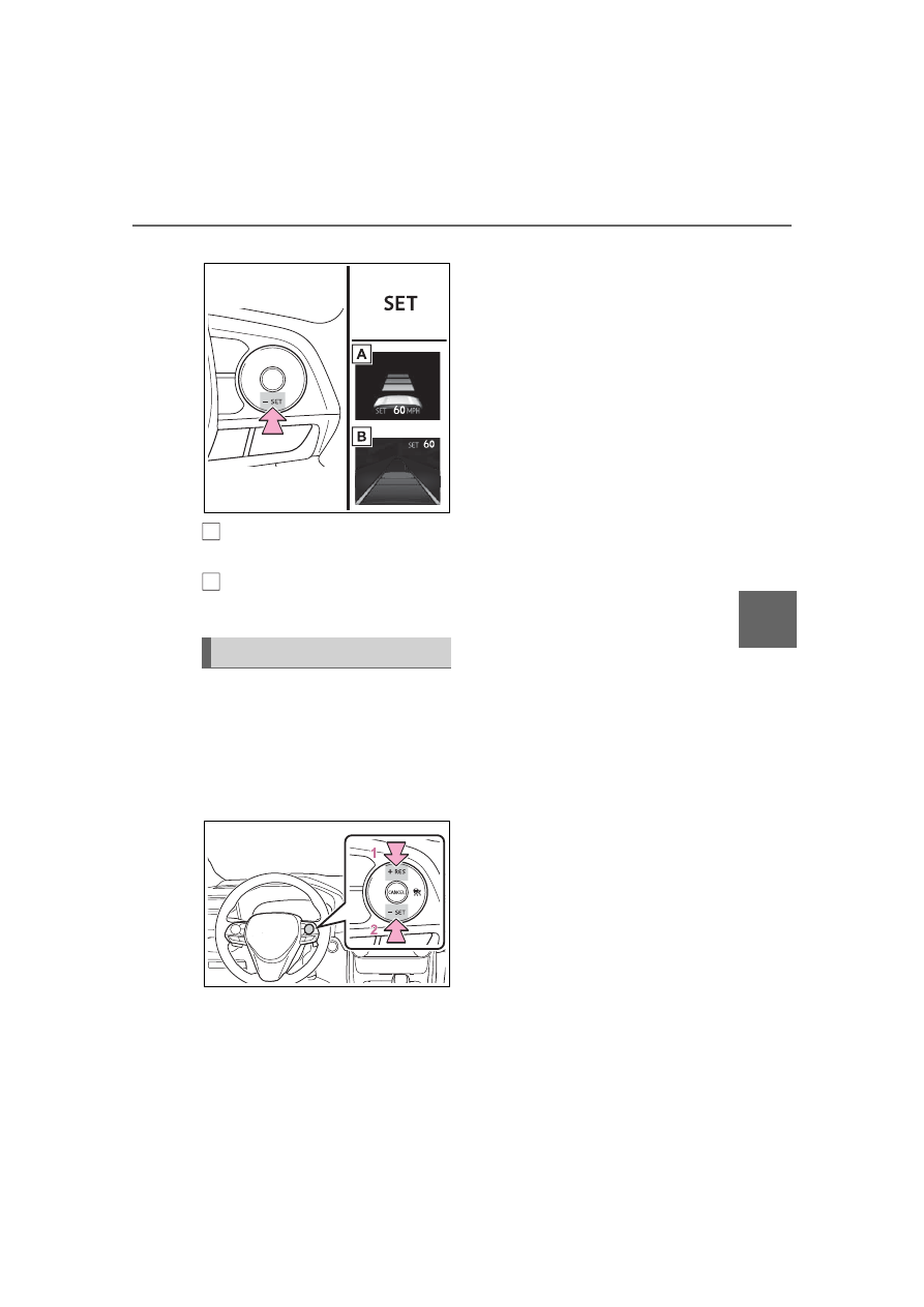
Adjusting the set speed by the 
switch

To change the set speed, press 
the “+RES” or “-SET” switch 
until the desired set speed is 
displayed.

1

Increases the speed (Except 
when the vehicle has been 
stopped by system control in 
vehicle-to-vehicle distance 

control mode)

2

Decreases the speed

Fine adjustment: Press the switch.
Large adjustment: Press and hold 
the switch to change the speed, 
and release when the desired 
speed is reached.

In the vehicle-to-vehicle dis-
tance control mode, the set 
speed will be increased or 
decreased as follows:

For the U.S. mainland and 
Hawaii

Fine adjustment: By 1 mph (1.6 
km/h)

*1

 or 1 km/h (0.6 mph)

*2

 each 

time the switch is pressed
Large adjustment: Increases or 
decreases in 1 mph (1.6 km/h)

*1

 or 

1 km/h (0.6 mph)

*2

 increments for 

as long as the switch is held

Except for the U.S. mainland 
and Hawaii

Fine adjustment: By 1 mph (1.6 
km/h)

*1

 or 1 km/h (0.6 mph)

*2

 each 

time the switch is pressed
Large adjustment: Increases or 
decreases in 5 mph (8 km/h)

*1

 or 5 

km/h (3.1 mph)

*2

 increments for as 

long as the switch is held

In the constant speed control 
mode (

P.375), the set speed 

will be increased or decreased 
as follows:

Fine adjustment: By 1 mph (1.6 
km/h)

*1

 or 1 km/h (0.6 mph)

*2

 each 

time the switch is pressed
Large adjustment: The speed will 
continue to change while the switch 

Adjusting the set speed

A

B

372

5-5. Using the driving support systems

is held.

*1

:When the set speed is shown in 

“MPH”

*2

:When the set speed is shown in 

“km/h”

Increasing the set speed by 
the accelerator pedal

1

Accelerate with accelerator 
pedal operation to the 
desired vehicle speed

2

Press the “-SET” switch

Pressing the switch changes the 
vehicle-to-vehicle distance as 
follows:

1

Long

2

Medium

3

Short

If a vehicle is running ahead of you, 
the preceding vehicle mark 

 will 

also be displayed.

Select a distance from the table 
below. Note that the distances 
shown correspond to a vehicle 
speed of 50 mph (80 km/h). 
Vehicle-to-vehicle distance 
increases/decreases in accor-
dance with vehicle speed. When 
the vehicle is stopped by system 
control, the vehicle stops at a 
certain vehicle-to-vehicle dis-
tance depending on the situa-
tion.

After the vehicle ahead of you 
starts off, press the “+RES” 
switch.
Your vehicle will also resume 
follow-up cruising if the acceler-

Changing the vehicle-to-
vehicle distance (vehicle-
to-vehicle distance con-
trol mode)

A

Vehicle-to-vehicle dis-
tance settings (vehicle-to-
vehicle distance control 
mode)

Distance options

Vehicle-to-vehi-

cle distance

Long

Approximately 

160 ft. (50 m)

Medium

Approximately 

130 ft. (40 m)

Short

Approximately 

100 ft. (30 m)

Resuming follow-up 
cruising when the vehicle 
has been stopped by sys-
tem control (vehicle-to-
vehicle distance control 
mode)

373

5-5. Using the driving support systems

5

Dr

iv

ing

ator pedal is depressed after the 
vehicle ahead of you starts off.

Vehicles with 7-inch multi-
information display

Vehicles with 12.3-inch multi-
information display

1

Pressing the cancel switch 
cancels the speed control.

The speed control is also canceled 
when the brake pedal is depressed. 
(When the vehicle has been 
stopped by system control, 
depressing the brake pedal does 
not cancel the setting.)

2

Pressing the “+RES” switch 
resumes the cruise control 
and returns vehicle speed to 
the set speed.

When your vehicle is too close 
to a vehicle ahead, and suffi-
cient automatic deceleration via 
the cruise control is not possi-
ble, the display will flash and the 
buzzer will sound to alert the 
driver. An example of this would 
be if another driver cuts in front 
of you while you are following a 
vehicle. Depress the brake 
pedal to ensure an appropriate 
vehicle-to-vehicle distance.

Vehicles with 7-inch multi-
information display

Vehicles with 12.3-inch multi-
information display

Canceling and resuming 
the speed control

A

B

Approach warning (vehi-
cle-to-vehicle distance 
control mode)

A

B

374

5-5. Using the driving support systems

Warnings may not occur 
when

In the following instances, warn-
ings may not occur even when 
the vehicle-to-vehicle distance is 
small.

When the speed of the pre-
ceding vehicle matches or 
exceeds your vehicle speed

When the preceding vehicle is 
traveling at an extremely slow 
speed

Immediately after the cruise 
control speed was set

When depressing the acceler-
ator pedal

While driving in vehicle-to-vehi-
cle distance control mode, this 
function will reduce the vehicle 
speed, if it is determined to be 
necessary.

Function operation

When the steering wheel begins 
to be turned, the vehicle speed 
will begin being reduced. When 
the steering wheel is returned to 
the center position, the vehicle 
speed reduction will end.
Depending on the situation, the 
vehicle speed will then return to 
the vehicle-to-vehicle distance 
control mode set speed.
In situations where vehicle-to-

vehicle distance control needs 
to operate, such as when a pre-
ceding vehicle cuts in front of 
your vehicle, the curve speed 
reduction function will be can-
celed.

Operation display

Vehicles with 7-inch multi-
information display

Vehicles with 12.3-inch multi-
information display

Displayed when the vehicle 
speed is being reduced.

When the vehicle speed reduction 
ends, the display will disappear.

Changing the settings of 
the curve speed reduction 
function

The curve speed reduction func-
tion can be enabled/disabled 
and the vehicle speed reduction 
strength can be adjusted on the 

 screen (

P.185, 196) of the 

multi-information display.

The setting will change each time 

Curve speed reduction 
function

A

B

375

5-5. Using the driving support systems

5

Dr

iv

ing

the 

 meter control switches is 

pressed.

When constant speed control 
mode is selected, your vehicle 
will maintain a set speed without 
controlling the vehicle-to-vehi-
cle distance. Select this mode 
only when vehicle-to-vehicle dis-
tance control mode does not 
function correctly due to a dirty 
radar, etc.

1

With the cruise control off, 
press and hold the cruise 
control main switch for 1.5 
seconds or more.

Immediately after the switch is 

pressed, the dynamic radar cruise 

control indicator will come on. After-

wards, it switches to the cruise con-

trol indicator.
Switching to constant speed control 

mode is only possible when operat-

ing the switch with the cruise con-

trol off.

2

Accelerate or decelerate, 
with accelerator pedal opera-
tion, to the desired vehicle 
speed (at or above approxi-
mately 20 mph [30 km/h]) 

and press the “-SET” switch 
to set the speed.

Cruise control “SET” indicator will 

come on.
The vehicle speed at the moment 

the switch is released becomes the 

set speed.
Adjusting the speed setting: 

P.371

Canceling and resuming the speed 

setting: 

P.373

Dynamic radar cruise control 

with full-speed range can be set 

when

The shift lever is in D.

The desired set speed can be set 

when the vehicle speed is approx-

imately 20 mph (30 km/h) or more. 

(However, when the vehicle speed 

is set while driving at below 

approximately 20 mph [30 km/h], 

the set speed will be set to 

approximately 20 mph [30 km/h].)

Accelerating after setting the 

vehicle speed

The vehicle can accelerate by oper-

ating the accelerator pedal. After 

accelerating, the set speed 

resumes. However, during vehicle- 

to-vehicle distance control mode, 

the vehicle speed may decrease 

below the set speed in order to 

maintain the distance to the preced-

ing vehicle.

Selecting constant speed 
control mode

376

5-5. Using the driving support systems

When the vehicle stops while 

follow-up cruising

Pressing the “+RES” switch while 

the vehicle ahead stops will 

resume follow-up cruising if the 

vehicle ahead starts off within 

approximately 3 seconds after the 

switch is pressed.

If the vehicle ahead starts off 

within 3 seconds after your vehicle 

stops, follow-up cruising will be 

resumed.

Automatic cancelation of vehi-

cle-to-vehicle distance control 

mode

Vehicle-to-vehicle distance control 

mode is automatically canceled in 

the following situations.

VSC is activated.

TRAC is activated for a period of 

time.

When the VSC or TRAC system is 

turned off.

The sensor cannot detect cor-

rectly because it is covered in 

some way.

When the brake control or output 

restriction control of a driving sup-

port system operates.

(For example: Pre-Collision Sys-

tem, Drive-Start Control)

The parking brake is operated.

The vehicle is stopped by system 

control on a steep incline.

The following are detected when 

the vehicle has been stopped by 

system control:

• The driver is not wearing a seat 

belt.

• The driver’s door is opened.

• The vehicle has been stopped for 

about 3 minutes

If vehicle-to-vehicle distance control 
mode is automatically canceled for 
any reasons other than the above, 
there may be a malfunction in the 
system. Contact your Toyota dealer.

Automatic cancelation of con-

stant speed control mode

Constant speed control mode is 

automatically canceled in the follow-

ing situations:

Actual vehicle speed is more than 

approximately 10 mph (16 km/h) 

below the set vehicle speed.

Actual vehicle speed falls below 

approximately 20 mph (30 km/h).

VSC is activated.

TRAC is activated for a period of 

time.

When the VSC or TRAC system is 

turned off.

When the brake control or output 

restriction control of a driving sup-

port system operates.

(For example: Pre-Collision Sys-

tem, Drive-Start Control)

The parking brake is operated.

If constant speed control mode is 
automatically canceled for any rea-
sons other than the above, there 
may be a malfunction in the system. 
Contact your Toyota dealer.

Situations in which the curve 

speed reduction function may 

not operate

In situations such as the following, 

the curve speed reduction function 

may not operate:

When the vehicle is being driven 

around a gentle curve

When the accelerator pedal is 

being depressed

When the vehicle is being driven 

around an extremely short curve

Brake operation

A brake operation sound may be 

heard and the brake pedal response 

may change, but these are not mal-

functions.

377

5-5. Using the driving support systems

5

Dr

iv

ing

Warning messages and buzzers 

for dynamic radar cruise con-

trol with full-speed range

Warning messages and buzzers are 

used to indicate a system malfunc-

tion or to inform the driver of the 

need for caution while driving. If a 

warning message is shown on the 

multi-information display, read the 

message and follow the instructions. 

(

P.338, 552)

When the sensor may not be 

correctly detecting the vehicle 

ahead

In the case of the following and 

depending on the conditions, oper-

ate the brake pedal when decelera-

tion of the system is insufficient or 

operate the accelerator pedal when 

acceleration is required.
As the sensor may not be able to 

correctly detect these types of vehi-

cles, the approach warning 

(

P.373) may not be activated.

Vehicles that cut in suddenly

Vehicles traveling at low speeds

Vehicles that are not moving in 

the same lane

Vehicles with small rear ends 

(trailers with no load on board, 

etc.)

Motorcycles traveling in the same 

lane

When water or snow thrown up by 

the surrounding vehicles hinders 

the detecting of the sensor

When your vehicle is pointing 

upwards (caused by a heavy load 

in the luggage compartment, etc.)

Preceding vehicle has an 

extremely high ground clearance

Conditions under which the 

vehicle-to-vehicle distance con-

trol mode may not function cor-

rectly

In the case of the following condi-

tions, operate the brake pedal (or 

accelerator pedal, depending on the 

situation) as necessary.
As the sensor may not be able to 

correctly detect vehicles ahead, the 

system may not operate properly.

When the road curves or when the 

lanes are narrow

When steering wheel operation or 

your position in the lane is unsta-

ble

378

5-5. Using the driving support systems

When the vehicle ahead of you 

decelerates suddenly

When driving on a road sur-

rounded by a structure, such as in 

a tunnel or on a bridge

While the vehicle speed is 

decreasing to the set speed after 

the vehicle accelerates by 

depressing the accelerator pedal

Situations in which the curve 

speed reduction function may 

not operate properly

In situations such as the following, 

the curve speed reduction function 

may not operate properly:

When the vehicle is being driven 

around a curve on an 

incline/decline

When the course of the vehicle 

differs from the shape of the curve

When the vehicle speed is exces-

sively high when entering a curve

When the steering wheel is sud-

denly operated

BSM (Blind Spot Moni-

tor)

The Blind Spot Monitor is a 
system that has 2 functions:

The BSM (Blind Spot Moni-
tor) function

Assists the driver in making a 
decision when changing lanes

The RCTA (Rear Cross 
Traffic Alert) function

Assists the driver when back-
ing up

These functions use the 
same sensors.

WARNING

Cautions regarding the use of 

the BSM function

The driver is solely responsible for 

safe driving. Always drive safely, 

taking care to observe your sur-

roundings.

The BSM function is a supple-

mentary function which alerts the 

driver that a vehicle is in a blind 

spot of the outside rear view mir-

rors or is approaching rapidly from 

behind into a blind spot. Do not 

overly rely on the BSM function. 

As the function cannot judge if it is 

safe to change lanes, over reli-

ance could lead to an accident 

resulting in death or serious 

injury.
As the system may not function 

correctly under certain condi-

tions, the driver’s own visual con-

firmation of safety is necessary.

379

5-5. Using the driving support systems

5

Dr

iv

ing

Multi-information display

Turning the BSM function/RCTA 
function on/off.

Outside rear view mirror indi-
cators

BSM function:
When a vehicle is detected in a 
blind spot of the outside rear view 
mirrors or approaching rapidly from 
behind into a blind spot, the outside 
rear view mirror indicator on the 

detected side will illuminate. If the 
turn signal lever is operated toward 
the detected side, the outside rear 
view mirror indicator will flash.
RCTA function:
When a vehicle approaching from 
the right or left at the rear of the 
vehicle is detected, both outside 
rear view mirror indicators will flash.

Multimedia Display (RCTA 
function only)

If a vehicle approaching from the 
right or left at the rear of the vehicle 
is detected, the RCTA icon 
(

P.384) for the detected side will 

be displayed.

BSM OFF indicator/RCTA 
OFF indicator

When the Blind Spot Monitor is dis-
abled, the BSM OFF indicator illu-
minates.
When the RCTA function is dis-
abled, the RCTA OFF indicator illu-
minates.

RCTA buzzer (RCTA func-
tion only)

If a vehicle approaching from the 
right or left at the rear of the vehicle 
is detected, a buzzer will sound 
from behind the rear seat.

The BSM function and the 
RCTA function can be 
enabled/disabled on the 


screen of the multi-information 
display. (

P.191, 203)

The BSM function/RCTA function 

WARNING

Cautions regarding the use of 

the RCTA function

There is a limit to the degree of 

recognition accuracy and control 

performance that this system can 

provide, do not overly rely on this 

system. The driver is always 

responsible for paying attention to 

the vehicle’s surroundings and 

driving safely.

System components

A

B

Turning the BSM func-
tion/RCTA function on/off

C

D

E

380

5-5. Using the driving support systems

will be enabled each time the power 
switch is turned to ON.

Outside rear view mirror indica-

tors visibility

In strong sunlight, the outside rear 

view mirror indicator may be difficult 

to see.

Hearing the RCTA buzzer

The RCTA buzzer may be difficult to 

hear over loud noises such as high 

audio volume.

When “Blind Spot Monitor 

Unavailable” or “Rear Cross 

Traffic Alert Unavailable” is 

shown on the multi-information 

display

The sensor voltage has become 

abnormal, or water, snow, mud, 

etc., may be built up in the vicinity of 

the sensor area of the rear bumper. 

(

P.380)

Removing the water, snow, mud, 

etc., from the vicinity of the sensor 

area should return it to normal.

Also, the sensor may not function 

normally when used in extremely 

hot or cold weather.

When “Blind Spot Monitor Mal-

function Visit Your Dealer” or 

“Rear Cross Traffic Alert Mal-

function Visit Your Dealer” is 

shown on the multi-information 

display

There may be a sensor malfunction 

or misaligned. Have the vehicle 

inspected at a Toyota dealer.

Customization

Some functions can be customized. 

(

P.191, 203)

WARNING

To ensure the system can 

operate properly

Blind Spot Monitor sensors are 

installed inside the left and right 

sides of the rear bumper respec-

tively. Observe the following to 

ensure the Blind Spot Monitor can 

function correctly.

Keep the sensors and the sur-

rounding areas on the rear 

bumper clean at all times. 

If a sensor or its surrounding 

area on the rear bumper is dirty 

or covered with snow, the Blind 

Spot Monitor may not operate 

and a warning message 

(

P.380) will be displayed. In 

this situation, clear off the dirt or 

snow and drive the vehicle with 

the operation conditions of the 

BSM function (

P.382) satis-

fied for approximately 10 min-

utes. If the warning message 

does not disappear, have the 

vehicle inspected by your 

Toyota dealer.

Do not subject a sensor or its 

surrounding area on the rear 

bumper to a strong impact. 

If a sensor is moved even 

slightly off position, the system 

may malfunction and vehicles 

may not be detected correctly. 

In the following situations, have 

your vehicle inspected by your 

Toyota dealer.

• A sensor or its surrounding area 

is subject to a strong impact.

381

5-5. Using the driving support systems

5

Dr

iv

ing

Vehicles that can be 
detected by the Blind Spot 
Monitor

The BSM function uses radar 
sensors to detect the following 
vehicles traveling in adjacent 
lanes and advises the driver of 
the presence of such vehicles 
via the indicators on the outside 
rear view mirrors.

Vehicles that are traveling in 
areas that are not visible 
using the outside rear view 
mirrors (the blind spots)

Vehicles that are approach-
ing rapidly from behind in 
areas that are not visible 
using the outside rear view 
mirrors (the blind spots)

The BSM function detection 
areas

The areas that vehicles can be 
detected in are outlined below.

WARNING

• If the surrounding area of a sen-

sor is scratched or dented, or 

part of them has become dis-

connected.

Do not disassemble the sensor.

Do not attach accessories, 

stickers (including transparent 

stickers), aluminum tape, etc. to 

a sensor or its surrounding area 

on the rear bumper.

Do not modify the sensor or sur-

rounding area on the rear 

bumper.

If a sensor or the rear bumper 

needs to be removed/installed 

or replaced, contact your 

Toyota dealer.

Do not paint the rear bumper 

any color other than an official 

Toyota color.

The Blind Spot Monitor 
function

A

B

382

5-5. Using the driving support systems

The range of each detection area 
is:

Approximately 1.6 ft. (0.5 m) 
to 11.5 ft. (3.5 m) from either 
side of the vehicle

The area between the side of the 
vehicle and 1.6 ft. (0.5 m) from the 
side of the vehicle cannot be 
detected.

Approximately 3.3 ft. (1 m) 
forward of the rear bumper

Approximately 9.8 ft. (3 m) 
from the rear bumper

Approximately 9.8 ft. (3 m) to 
197 ft. (60 m) from the rear 
bumper

The greater the difference in speed 
between your vehicle and the 
detected vehicle is, the farther 
away the vehicle will be detected, 
causing the outside rear view mirror 
indicator to illuminate or flash.

The BSM function is operational 

when

The BSM function is operational 

when all of the following conditions 

are met:

The BSM function is on.

The shift lever is in a position 

other than R.

The vehicle speed is greater than 

approximately 10 mph (16 km/h).

The BSM function will detect a 

vehicle when

The BSM function will detect a vehi-

cle present in the detection area in 

the following situations:

A vehicle in an adjacent lane over-

takes your vehicle.

You overtake a vehicle in an adja-

cent lane slowly.

Another vehicle enters the detec-

tion area when it changes lanes.

Conditions under which the 

system will not detect a vehicle

The BSM function is not designed to 

detect the following types of vehi-

cles and/or objects:

Small motorcycles, bicycles, 
pedestrians, etc.

*

Vehicles traveling in the opposite 

direction

Guardrails, walls, signs, parked 

vehicles and similar stationary 
objects

*

Following vehicles that are in the 
same lane

*

Vehicles traveling 2 lanes away 
from your vehicle

*

Vehicles which are being over-

taken rapidly by your vehicle

*

: Depending on the conditions, 

detection of a vehicle and/or 
object may occur.

A

B

C

D

383

5-5. Using the driving support systems

5

Dr

iv

ing

Conditions under which the 

system may not function cor-

rectly

The BSM function may not detect 

vehicles correctly in the following 

situations:

• When the sensor is misaligned 

due to a strong impact to the sen-

sor or its surrounding area

• When mud, snow, ice, a sticker, 

etc., is covering the sensor or sur-

rounding area on the rear bumper

• When driving on a road surface 

that is wet with standing water 

during bad weather, such as 

heavy rain, snow, or fog

• When multiple vehicles are 

approaching with only a small gap 

between each vehicle

• When the distance between your 

vehicle and a following vehicle is 

short

• When there is a significant differ-

ence in speed between your vehi-

cle and the vehicle that enters the 

detection area

• When the difference in speed 

between your vehicle and another 

vehicle is changing

• When a vehicle enters a detection 

area traveling at about the same 

speed as your vehicle

• As your vehicle starts from a stop, 

a vehicle remains in the detection 

area

• When driving up and down con-

secutive steep inclines, such as 

hills, dips in the road, etc.

• When driving on roads with sharp 

bends, consecutive curves, or 

uneven surfaces

• When vehicle lanes are wide, or 

when driving on the edge of a 

lane, and the vehicle in an adja-

cent lane is far away from your 

vehicle

• When an accessory (such as a 

bicycle carrier) is installed to the 

rear of the vehicle

• When there is a significant differ-

ence in height between your vehi-

cle and the vehicle that enters the 

detection area

• Immediately after the BSM func-

tion/RCTA function are turned on

• When towing a trailer

Instances of the BSM function 

unnecessarily detecting a vehicle 

and/or object may increase in the 

following situations:

• When the sensor is misaligned 

due to a strong impact to the sen-

sor or its surrounding area

• When the distance between your 

vehicle and a guardrail, wall, etc. 

that enters the detection area is 

short

• When driving up and down con-

secutive steep inclines, such as 

hills, dips in the road, etc.

• When vehicle lanes are narrow, or 

when driving on the edge of a 

lane, and a vehicle traveling in a 

lane other than the adjacent lanes 

enters the detection area

• When driving on roads with sharp 

bends, consecutive curves, or 

uneven surfaces

• When the tires are slipping or 

spinning

• When the distance between your 

vehicle and a following vehicle is 

short

• When an accessory (such as a 

bicycle carrier) is installed to the 

rear of the vehicle

• When the vehicle throws up water 

or snow behind.

Operation of the RCTA 
function

The RCTA function uses radar 
sensors to detect vehicles 
approaching from the right or left 
at the rear of the vehicle and 
alerts the driver of the presence 
of such vehicles by flashing the 
outside rear view mirror indica-
tors and sounding a buzzer.

The Rear Cross Traffic 
Alert function

384

5-5. Using the driving support systems

Approaching vehicles

Detection areas

RCTA icon display

When a vehicle approaching 
from the right or left at the rear 
of the vehicle is detected, the 
following will be displayed on 
the Multimedia Display.
Example: Vehicles are 
approaching from both sides of 
the vehicle

When the Toyota parking 
assist monitor (if equipped) is 
displayed

When the panoramic view 
monitor (if equipped) is dis-
played

The RCTA function detec-
tion areas

The areas that vehicles can be 
detected in are outlined below.

The buzzer can alert the driver of 
faster vehicles approaching from 
farther away.

Example:

The RCTA function is opera-

tional when

The RCTA function operates when 

all of the following conditions are 

met:

A

B

Approach-

ing vehicle

Speed


Approxi-

mate alert 

distance

Fast

34 mph 

(56 km/h)

131 ft. (40 

m)

Slow

5 mph (8 

km/h)

18 ft. (5.5 

m)

A

385

5-5. Using the driving support systems

5

Dr

iv

ing

The RCTA function is on.

The shift lever is in R.

The vehicle speed is less than 

approximately 9 mph (15 km/h).

The approaching vehicle speed is 

between approximately 5 mph (8 

km/h) and 34 mph (56 km/h).

Setting the buzzer volume

The buzzer volume can be adjusted 

on the multi-information display. 

(

P.191, 203)

Conditions under which the 

system will not detect a vehicle

The RCTA function is not designed 

to detect the following types of vehi-

cles and/or objects.

Vehicles approaching from 

directly behind

Vehicles backing up in a parking 

space next to your vehicle

Vehicles that the sensors cannot 

detect due to obstructions

Guardrails, walls, signs, parked 

vehicles and similar stationary 
objects

*

Small motorcycles, bicycles, 
pedestrians, etc.

*

Vehicles moving away from your 

vehicle

Vehicles approaching from the 

parking spaces next to your vehi-
cle

*

The distance between the sensor 

and approaching vehicle gets too 

close

*

: Depending on conditions, detec-

tion of a vehicle and/or object may 

occur.

Situations in which the system 

may not operate properly

The RCTA function may not detect 

vehicles correctly in the following 

situations:

When the sensor is misaligned 

due to a strong impact to the sen-

sor or its surrounding area.

When mud, snow, ice, a sticker, 

etc., is covering the sensor or sur-

rounding area on the rear bumper.

When driving on a road surface 

that is wet with standing water 

during bad weather, such as 

heavy rain, snow, or fog.

When multiple vehicles are 

approaching with only a small gap 

between each vehicle.

When a vehicle is approaching at 

high speed.

When equipment that may 

obstruct a sensor is installed, such 

as a towing eyelet, bumper pro-

tector (an additional trim strip, 

etc.), bicycle carrier, or snow 

plow.

When backing up on a slope with 

a sharp change in grade.

When backing out of a sharp 

angle parking spot.

386

5-5. Using the driving support systems

When towing a trailer.

When there is a significant differ-

ence in height between your vehi-

cle and the vehicle that enters the 

detection area.

When a sensor or the area around 

a sensor is extremely hot or cold.

If the suspension has been modi-

fied or tires of a size other than 

specified are installed.

If the front of the vehicle is raised 

or lowered due to the carried load.

When turning while backing up.

When a vehicle turns into the 

detection area.

Situations in which the system 

may operate even if there is no 

possibility of a collision

Instances of the RCTA function 

unnecessarily detecting a vehicle 

and/or object may increase in the 

following situations:

When the parking space faces a 

street and vehicles are being 

driven on the street.

When the distance between your 

vehicle and metal objects, such as 

a guardrail, wall, sign, or parked 

vehicle, which may reflect electri-

cal waves toward the rear of the 

vehicle, is short.

When equipment that may 

obstruct a sensor is installed, such 

as a towing eyelet, bumper pro-

tector (an additional trim strip, 

etc.), bicycle carrier, or snow 

plow.

When a vehicle passes by the 

side of your vehicle.

When a detected vehicle turns 

while approaching the vehicle.


Content      ..     21      22      23      24     ..