Toyota Highlander Hybrid (2023 year). Manual in english - page 7
 

  Index      Toyota     Toyota Highlander Hybrid (2023 year). Manual in english


Search            copyright infringement  


Content      ..     5      6      7      8     ..


Toyota Highlander Hybrid (2023 year). Manual in english - page 7


110

2-1. Instrument cluster

ECO Accelerator Guid-
ance/Eco score

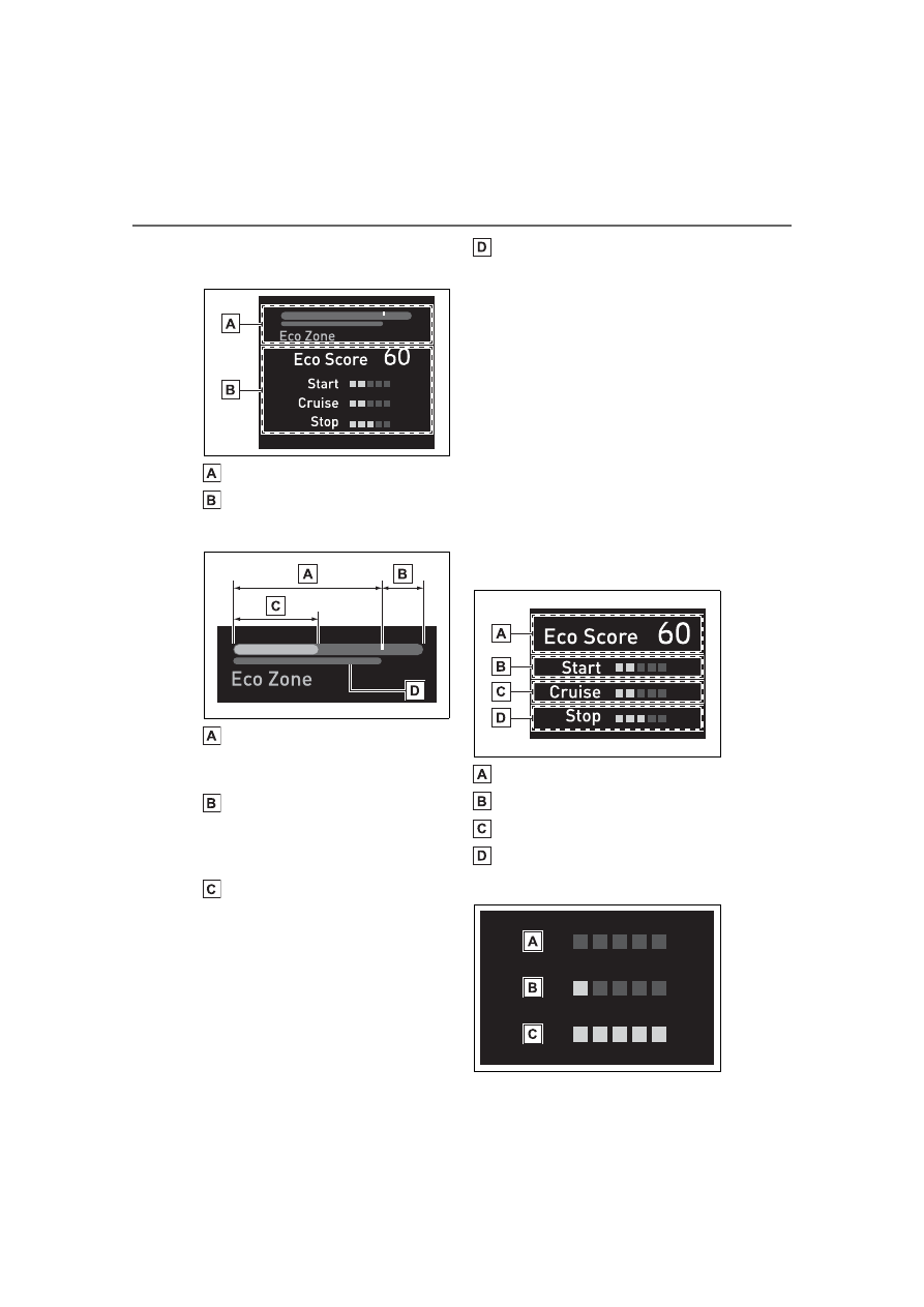
ECO Accelerator Guidance
Eco score

ECO Accelerator Guidance

Eco area

Indicates that the vehicle is being 
driven in an Eco-friendly manner.

Power area

Indicates that the Eco-friendly driv-
ing range is being exceeded 
(during full power driving, etc.)

Current accelerator pedal 
operation

Displayed as a green bar when 
within the Eco area.
Eco-friendly acceleration can be 
achieved by keeping the accelera-
tor pedal operation display within 
the range indicated by the blue bar. 
(

P.185)

Zone of Eco acceleration

Displayed as a blue bar, and rep-
resents an estimated suitable 
accelerator pedal operation range 
for the current driving conditions, 
such as starting off or cruising.
This display changes according to 
situation, such as when starting off 
or cruising.

Eco score

The following 3 Eco driving meth-
ods are evaluated in 5 levels: 
Smooth start-off acceleration, driv-
ing without sudden acceleration, 
and smooth stopping. When the 
vehicle is stopped, an Eco score 
out of 100 points will be displayed.

Score result
Eco start status
Eco cruise status
Eco stop status

How to read the bar display

111

2-1. Instrument cluster

2

Vehicle

 statu

s information an

d in
dicator

s

Not yet evaluated
Low
High

• After the hybrid system is started, 

the Eco score will not be dis-
played until the vehicle speed 
exceeds approximately 19 mph 
(30 km/h).

• The Eco score will be reset each 

time the hybrid system is started.

• When the hybrid system is 

stopped, the total score of the 
current trip will be displayed.

Driving support system 
information display

Select to display the operational 
status of the following systems:

PCS (Pre-Collision System) 
(

P.242)

LTA (Lane Tracing Assist) 
(

P.253)

Dynamic radar cruise control 
with full-speed range 
(

P.263)

Audio system-linked dis-
play

Displays the audio source or 
track.

Drive information

Drive information 1
Drive information 2

Displays the following depend-
ing on which drive information 
type and drive information items 
were selected in 

. (

P.108)

Average speed: Displays the 
average vehicle speed since 
hybrid system start

Trip distance: Displays the 
distance driven since hybrid 
system start

Trip time: Displays the 
elapsed time since hybrid sys-
tem start

Drive information of TRIP 
A/B

Drive information of trip A/B 1
Drive information of trip A/B 2

Displays the following depend-
ing on which drive information 
type and drive information items 
were selected in 

. (

P.108)

Average speed: Displays the 
average vehicle speed of trip 
A/B

Trip distance: Displays the 

112

2-1. Instrument cluster

distance driven of trip A/B

Trip time: Displays the 
elapsed time of trip A/B

AWD Control (if equipped)

The illustration used is intended as 
an example, and may differ from the 
image that is actually displayed on 
the multi-information display.

Torque distribution display

Displays the drive status of each 
wheel in 6 steps from 0 to 5.

The ECO Accelerator Guid-

ance/Eco score will not operate 

when

The ECO Accelerator Guidance/Eco 

score will not operate in the follow-

ing situations:

The Hybrid System Indicator is not 

operating.

The vehicle is being driven using 

the dynamic radar cruise control 

with full-speed range.

Displays suggestions to the 
driver in the following situations. 
To select a response to a dis-
played suggestion, use the 
meter control switches.

Suggestion to turn off the 
headlights

If the headlights are left on for a 
certain amount of time after the 
power switch has been turned 
off, if the headlight switch is in 
the “AUTO” position, a sugges-
tion message will be displayed 
asking if you wish to turn the 
headlights off.
To turn the headlights off, select 
“Yes”.

If the driver's door is opened after 
the power switch is turned off, this 
suggestion message will not be dis-
played.

Customization

Some functions can be customized. 

(

P.510)

Vehicle functions and set-
tings that can be changed

P.510

Meter display settings

P.108

Suspension of the settings dis-

play

Some settings cannot be changed 

while driving. When changing set-

tings, park the vehicle in a safe 

place.

If a warning message is displayed, 

operation of the settings display 

will be suspended.

Suggestion function

Settings display

113

2-1. Instrument cluster

2

Vehicle

 s

ta

tu

s information an

d in
dicat

or

s

WARNING

Cautions during setting up 

the display

If the hybrid system is operating 

while changing certain settings on 

the settings display, ensure that 

the vehicle is parked in a place 

with adequate ventilation. In a 

closed area such as a garage, 

exhaust gases including harmful 

carbon monoxide (CO) may col-

lect and enter the vehicle. This 

may lead to death or a serious 

health hazard.

NOTICE

During setting up the display

To prevent 12-volt battery dis-

charge, ensure that the hybrid 

system is operating while setting 

up the display features.

114

2-1. Instrument cluster

*

: If equipped

Illustrations used in this text are intended as examples, and may differ from 
the image that is actually displayed by the head-up display.

Shift position display (

P.213)

Speed limit/RSA (Road Sign Assist) display area

Displays the following items:
• Speed limit of the current road (linked to the navigation system) (U.S.A. 

only)

• RSA (Road Sign Assist) display (if equipped) (

P.275)

Vehicle speed display area
Hybrid System Indicator/Tachometer/Outside temperature 
(

P.117)

Navigation system-linked display area (if equipped) (

P.117)

Displays the following items, which are linked to the navigation system:
• Route guidance to destination
• Street name
• Compass (heading-up display)

Head-up display

*

The head-up display is linked to the meters and navigation 
system (if equipped) and projects a variety of information in 
front of the driver, such as the current vehicle speed and route 
guidance to a set destination.

System components

115

2-1. Instrument cluster

2

Vehicle

 s

ta

tu

s information an

d in
dicat

or

s

Driving assist system status display area (

P.118)

Message display area (

P.118)

The following pop-up displays will be displayed in certain situations:
• Warning/message
• Hands-free system status
• Audio system operation status

Head-up display will operate 

when

The power switch is in ON.

When using the head-up dis-

play

The head-up display may seem 

dark or hard to see when viewed 

through sunglasses, especially 

polarized sunglasses. Adjust the 

brightness of the head-up display or 

remove your sunglasses.

Outside temperature display

If the outside temperature becomes 

approximately 37°F (3°C) or lower, 

the low outside temperature indica-

tor will flash for 10 seconds then the 

low outside temperature indicator 

and outside temperature display will 

turn off. The low outside tempera-

ture indicator will operate again if 

the outside temperature becomes 

approximately 41°F (5°C) or more 

and then decreases to 37°F (3°C) or 

lower.

WARNING

Before using the head-up dis-

play

Check that the position and 

brightness of the head-up dis-

play image does not interfere 

with safe driving. Incorrect 

adjustment of the image’s posi-

tion or brightness may obstruct 

the driver’s view and lead to an 

accident, resulting in death or 

serious injury.

Do not continuously look at the 

head-up display while driving as 

you may fail to see pedestrians, 

objects on the road, etc. ahead 

of the vehicle.

NOTICE

To prevent damage to compo-

nents

Do not place any drinks near 

the head-up display projector. If 

the projector gets wet, electrical 

malfunctions may result.

Do not place anything on or put 

stickers onto the head-up dis-

play projector. Doing so could 

interrupt head-up display indica-

tions.

Do not touch the inside of the 

head-up display projector or 

thrust sharp edges or the like 

into the projector. Doing so 

could cause mechanical mal-

functions.

116

2-1. Instrument cluster

Changing settings of the 
head-up display

Select 

 on the multi-informa-

tion display (

P.510) and then 

“HUD”.

Enabling/disabling the 
head-up display

Press 

 to enable/disable the 

head-up display.

Changing the head-up dis-
play settings

Press and hold 

 to display the 

following settings.

HUD Brightness/Position

Select to adjust the brightness and 
vertical position of the head-up dis-
play.

HUD Driving Support

• Tachometer Settings
Blank/Hybrid System/Tachometer
Select to change the display to 
blank (no display)/Hybrid System 
Indicator/tachometer.
Select to enable/disable the follow-
ing items:
• Navigation (if equipped)
• Driving Assist
• Compass (if equipped)
• Audio

HUD Rotation

Select to adjust the angle of the 
head-up display.

Press the 

 or 

 switch to 

adjust the angle of the head-up dis-
play.

Enabling/disabling of the 

head-up display

If the head-up display is disabled, it 

will remain disabled when the power 

switch is turned off then back to ON.

Display brightness

The brightness of the head-up dis-
play can be adjusted on 

 of the 

multi-information display. Also, it is 

automatically adjusted according to 

the ambient brightness.

Automatic adjustment of the 

head-up display position (vehi-

cles with driving position mem-

ory)

A desired head-up display position 

can be entered to memory and 

recalled automatically by the driving 

position memory system. (

P.153)

When the 12-volt battery is dis-

connected

The customize settings of the 

head-up display will be reset.

Customization

Some functions can be customized. 

(

P.510)

Using the head-up display

WARNING

Caution for changing settings 

of the head-up display

As the hybrid system needs to be 

operating while changing the set-

tings of the head-up display, 

ensure that the vehicle is parked 

in a place with adequate ventila-

tion. In a closed area such as a 

garage, exhaust gases including 

harmful carbon monoxide (CO) 

may collect and enter the vehicle. 

This may lead to death or a seri-

ous health hazard.

117

2-1. Instrument cluster

2

Vehicle

 s

ta

tu

s information an

d in
dicat

or

s

Hybrid System Indicator

Charge area
Hybrid Eco area
Eco area
Power area

Displayed content is the same as 
that displayed on the meter (Hybrid 
System Indicator). For details, refer 
to P.94.

Tachometer

Displays the engine speed in 
revolutions per minute.

Outside temperature

Displayed in the following situa-
tions:

When the power switch is 
turned to ON (Displayed for 

approximately 10 seconds)

When the low outside tem-
perature indicator is flashing

Displayed content is the same 
as that displayed on the 
multi-information display. For 
details, refer to the explanation 
of the outside temperature dis-
play on the multi-information 
display. (

P.94)

Displays the following naviga-
tion system linked items:
(Refer to “MULTIMEDIA 
OWNER’S MANUAL”.)

Route guidance to destina-
tion

Displayed when the navigation 
system is performing route guid-
ance. When approaching an 
intersection, an arrow indicating 
the suggested direction of travel 
will be displayed.

Street name

Depending on the situation, the 
names of the streets of an 
approaching intersection will be 
displayed.

Compass (heading-up dis-
play)

Displays the direction of travel.

Street name display

Depending on the situation, such as 

when no information is available in 

NOTICE

When changing the settings 

of the head-up display

To prevent 12-volt battery dis-

charge, ensure that the hybrid 

system is operating while the 

changing the settings of the 

head-up display.

Hybrid System Indica-
tor/Tachometer/Outside 
temperature

Navigation system-linked 
display area (if equipped)

118

2-1. Instrument cluster

map data, etc., the street names of 

an intersection may not be dis-

played.

Displays the operational status 
of the following systems:

LTA (Lane Tracing Assist) 
(

P.253)

Dynamic radar cruise control 
with full-speed range 
(

P.263)

PCS (Pre-Collision System) 
(

P.242)

Parking Support Brake func-
tion (for static objects) 
(

P.304)

Intuitive parking assist 
(

P.283)

Drive-Start Control (

P.184)

Brake Override System 
(

P.185)

Displayed content is the same as 
that displayed on the multi-informa-
tion display. For details, refer to the 
explanations of each system.

Displays the following 
multi-information display linked 
icons and a message:

: Master warning icon

Displayed when a warning mes-
sage is displayed on the multi-infor-
mation display. (

P.456)

: Information icon

Displayed when a sugges-
tion/advice pop-up display is dis-
played on the multi-information 
display. (

P.112)

Depending on the situation, the 
following will be displayed:

Warning/Message

Depending on the situation, a 
warning message or other mes-
sage will be displayed.

Warning messages

Certain warning messages can be 
displayed.

Pop-up displays

When the driving assist system 
operates, some of the information 
displayed on the multi-information 
display will be displayed on the 
head-up display as a pop-up dis-
play.

Hands-free system status

Displayed when the hands-free 
system is operated.
(Refer to “MULTIMEDIA 
OWNER’S MANUAL”.)

Audio system operation 
status

Displayed when the audio sys-
tem is operated.
(Refer to “MULTIMEDIA 
OWNER’S MANUAL”.)

Driving assist system sta-
tus display area

/

 icons

Message display area

119

2-1. Instrument cluster

2

Vehicle

 statu

s information an

d in
dicator

s

Pop-up displays

Depending on the pop-up display, 

the currently displayed item in the 

message display area may be tem-

porarily not displayed. The item will 

be displayed after the pop-up dis-

play is no longer displayed.

Audio system screen
Multi-information display
Meter control switches

Multi-information display

Press the meter control 
switches on the steering wheel 
several times to select the 
energy monitor display.

Audio system screen

1

Select 

 on the main menu.

2

Select “Energy flow”.

Reading the display

The arrows will appear in accor-
dance with the energy flow. 
When there is no energy flow, 

Energy monitor/con-

sumption screen

The state of the hybrid sys-
tem can be viewed on the 
multi-information display 
and audio system display.

System components

Energy monitor

120

2-1. Instrument cluster

arrows will not be displayed.

The color of the arrows will change 
as follows
Green or blue: When the hybrid 
battery (traction battery) is regener-
ated or charged.
Yellow or orange: When the hybrid 
battery (traction battery) is in use.
Red: When the gasoline engine is 
in use.

Multi-information display 
(7-inch display)

The image shows all the arrows as 
an example. The actual display will 
vary depending on conditions.

Gasoline engine
Hybrid battery (traction bat-
tery)
Front tires

Rear tires

*

*

: For FF vehicles, the arrows to 


are not displayed.

Multi-information display 
(12.3-inch display)

The image shows all the arrows as 
an example. The actual display will 
vary depending on conditions.

Gasoline engine
Hybrid battery (traction bat-
tery)
Front tires

Rear tires

*

*

: For FF vehicles, the arrows to 


are not displayed.

Audio system screen

The image shows all the arrows as 
an example. The actual display will 
vary depending on conditions.

Gasoline engine
Front electric motor (traction 
motor)
Hybrid battery (traction bat-
tery)

A

C

D

B

121

2-1. Instrument cluster

2

Vehicle

 statu

s information an

d in
dicator

s

Rear electric motor (traction 
motor)

*1

Rear tires

*2

Front tires

*1

:AWD models only

*2

:For FF vehicles, the arrows to 


are not displayed.

Remaining charge amount 

warning of hybrid battery (trac-

tion battery)

The buzzer sounds intermittently 

when the hybrid battery (traction 

battery) remains without charging 

while the shift lever is in N, or the 

remaining charge amount drops 

below a certain level. If the 

remaining charge amount drops 

further, the buzzer sounds contin-

uously.

When a warning message is 

shown on the multi-information 

display and the buzzer sounds, 

follow the instructions displayed 

on the screen to perform trouble-

shooting.

Trip information

1

Select 

 on the main menu.

2

Select “Trip information”.

If a screen other than “Current” is 
displayed, select “Current”.

Resetting the consumption 
data
Fuel consumption in the past 
15 minutes
Current fuel consumption
Average vehicle speed since 
the hybrid system was 
started.
Elapsed time since the hybrid 
system was started.
Cruising range

Average fuel consumption for 
the past 15 minutes is divided 
by color into past averages and 
averages attained since the 
power switch was last turned to 
ON. Use the displayed average 
fuel consumption as a refer-
ence.

The image is an example only, and 
may vary slightly from actual condi-
tions.

History

1

Select 

 on the main menu.

2

Select “Trip information”.

If a screen other than “History” is 

displayed, select “History”.

Consumption

122

2-1. Instrument cluster

Best recorded fuel consump-
tion
Latest fuel consumption
Previous fuel consumption 
record
Resetting the history data
Updating the latest fuel con-
sumption data

The average fuel consumption 
history is divided by color into 
past averages and the average 
fuel consumption since the last 
updated. Use the displayed 
average fuel consumption as a 
reference.

The image is an example only, and 
may vary slightly from actual condi-
tions.

Updating the history data

Update the latest fuel consumption 

by selecting “Update” to measure 

the current fuel consumption again.

Resetting the data

The fuel consumption data can be 

deleted by selecting “Clear data”.

Cruising range

Displays the estimated maximum 

distance that can be driven with the 

quantity of fuel remaining.
This distance is computed based on 

your average fuel consumption. 

As a result, the actual distance that 

can be driven may differ from that 

displayed.

123

3

3

Before driv

ing

Before driving

.

3-1. Key information

Keys ............................

124

3-2. Opening, closing and 

locking the doors

Side doors...................

127

Back door....................

131

Smart key system .......

142

3-3. Adjusting the seats

Front seats ..................

147

Rear seats...................

148

Driving position memory

..................................

153

Head restraints............

156

3-4. Adjusting the steering 

wheel and mirrors

Steering wheel ............

159

Inside rear view mirror

..................................

160

Digital Rearview Mirror

..................................

161

Outside rear view mirrors

..................................

171

3-5. Opening, closing the win-

dows and moon roof

Power windows ...........

173

Moon roof....................

176

Panoramic moon roof..

179

124

3-1. Key information

3-1.Key information

The following keys are provided 
with the vehicle.

Electronic keys

• Operating the smart key system 

(

P.142)

• Operating the wireless remote 

control function (

P.125)

Mechanical keys
Key number plate

When riding in an aircraft

When bringing an electronic key 

onto an aircraft, make sure you do 

not press any buttons on the elec-

tronic key while inside the aircraft 

cabin. If you are carrying an elec-

tronic key in your bag, etc., ensure 

that the buttons are not likely to be 

pressed accidentally. Pressing a 

button may cause the electronic key 

to emit radio waves that could inter-

fere with the operation of the air-

craft.

Electronic key battery depletion

The standard battery life is 1 to 2 

years.

If the battery becomes low, an 

alarm will sound in the cabin when 

the hybrid system is stopped.

To reduce key battery depletion 

when the electronic key is to not 

be used for long periods of time, 

set the electronic key to the bat-

tery-saving mode. (

P.143)

As the electronic key always 

receives radio waves, the battery 

will become depleted even if the 

electronic key is not used. The fol-

lowing symptoms indicate that the 

electronic key battery may be 

depleted. Replace the battery 

when necessary.

• The smart key system or the wire-

less remote control does not oper-

ate.

• The detection area becomes 

smaller.

• The LED indicator on the key sur-

face does not turn on.

To avoid serious deterioration, do 

not leave the electronic key within 

3 ft. (1 m) of the following electri-

cal appliances that produce a 

magnetic field:

• TVs

• Personal computers

• Cellular phones, cordless phones 

and battery chargers

• Recharging cellular phones or 

cordless phones

• Table lamps

• Induction cookers

Replacing the battery

P.423

Confirmation of the registered 

key number

The number of keys already regis-

tered to the vehicle can be con-

firmed. Ask your Toyota dealer for 

details.

If “A New Key has been Regis-

tered Contact Your Dealer for 

Details” is shown on the 

multi-information display

This message will be displayed 

each time the driver’s door is 

opened when the doors are 

unlocked from the outside for 

approximately 10 days after a new 

electronic key has been registered.

Keys

The keys

125

3-1. Key information

3

Before driv

ing

If this message is displayed but you 

have not had a new electronic key 

registered, ask your Toyota dealer to 

check if an unknown electronic key 

(other than those in your posses-

sion) has been registered.

The electronic keys are 
equipped with the following 
wireless remote control:

Locks the doors (

P.127)

Unlocks the doors (

P.127)

Opens the windows

*1

 and 

moon roof

*1, 2

 (

P.127)

Opens and closes the power 
back door (

P.133)

Sounds the alarm

*1

:These settings must be custom-

ized at your Toyota dealer.

NOTICE

To prevent key damage

Do not drop the keys, subject 

them to strong shocks or bend 

them.

Do not expose the keys to high 

temperatures for long periods of 

time.

Do not get the keys wet or wash 

them in an ultrasonic washer, 

etc.

Do not attach metallic or mag-

netic materials to the keys or 

place the keys close to such 

materials.

Do not disassemble the keys.

Do not attach a sticker or any-

thing else to the surface of the 

electronic key.

Do not place the keys near 

objects that produce magnetic 

fields, such as TVs, audio sys-

tems and induction cookers.

Do not place the keys near 

medical electrical equipment 

such as low-frequency therapy 

equipment or microwave ther-

apy equipment, and do not 

receive medical attention with 

the keys on your person.

Carrying the electronic key 

on your person

Carry the electronic key 3.9 in. 

(10 cm) or more away from elec-

tric appliances that are turned on. 

Radio waves emitted from electric 

appliances within 3.9 in. (10 cm) 

of the electronic key may interfere 

with the key, causing the key to 

not function properly.

In case of a smart key system 

malfunction or other 

key-related problems

P.477

When an electronic key is lost

P.475

Wireless remote control


Content      ..     5      6      7      8     ..