Toyota Corolla (2023 year). Manual in english - page 15
 

  Index      Toyota     Toyota Corolla (2023 year). Manual in english


Search            copyright infringement  


Content      ..     13      14      15      16     ..


Toyota Corolla (2023 year). Manual in english - page 15


228

4-5. Using the driving support systems

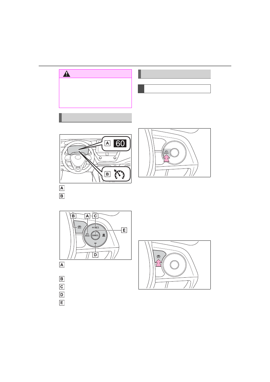
Meter display

Set vehicle speed
Cruise control indicator

Switches

Driving assist mode select 
switch
Driving assist switch
“+” switch / “RES” switch
“-” switch
Cancel switch

1

Press the driving assist mode 
select switch to select cruise 
control.

The cruise control indicator will illu-

minate.

2

Using the accelerator pedal, 
accelerate to the desired 
vehicle speed (approxi-
mately 20 mph [30 km/h] or 
more), and press the driving 
assist switch to set the set 
vehicle speed.

The vehicle speed at the moment 

the switch is released will be the set 

vehicle speed.

WARNING

Vehicle speed may exceed the set 

speed when driving down a steep 

hill.

When it is necessary to disable 

the system: 

P.184

System Components

Using the cruise control

Setting the vehicle speed

229

4-5. Using the driving support systems

4

Dr

iv

ing

Adjusting the set vehicle 
speed using the switches

To change the set vehicle 
speed, press the “+” or “-” switch 
until the desired speed is dis-
played.

1

Increase set vehicle speed

2

Decrease set vehicle speed

The set vehicle speed will 
increase or decrease as follows:

Fine adjustment: By 1 mph (1.6 
km/h) or 1 km/h (0.6 mph) each 
time the switch is pressed
Large adjustment: Increases con-
tinuously while the switch is 
pressed and held

Increasing the set vehicle 
speed using the accelerator 
pedal

1

Depress the accelerator 
pedal to accelerate the vehi-
cle to the desired vehicle 
speed.

2

Press the “+” switch.

1

Press the cancel switch or 
driving assist switch to cancel 
control.

Control will also be canceled if the 
brake pedal is depressed.

2

Press the “RES” switch to 
resume control.

Automatic cancellation of the 

cruise control

In the following situations, the cruise 

control will be canceled automati-

cally:

When the vehicle speed drops 

approximately 10 mph (16 km/h) 

or more below the set vehicle 

speed

When the vehicle speed drops 

below approximately 20 mph (30 

km/h)

When the brake control or output 

restriction control of a driving sup-

port system operates (For exam-

ple: PCS, drive-start control)

When the parking brake has been 

operated

Situations in which some or all of 

the functions of the system cannot 

operate: 

P.189

Adjusting the set vehicle 
speed

Canceling/resuming con-
trol

230

4-5. Using the driving support systems

Operation of this system is sep-
arated into 4 control states. 

Emergency Driving 

Stop System

The emergency driving stop 
system is a system which 
automatically decelerates 
and stops the vehicle within 
its lane if the driver 
becomes unable to continue 
driving the vehicle, such as 
if they have suffered a medi-
cal emergency, etc.

During LTA (Lane Tracing 
Assist) control, if the sys-
tem does not detect driving 
operations, such as if the 
driver is not holding the 
steering wheel, and deter-
mines the driver is not 
responsive, the vehicle will 
be decelerated and stopped 
within its current lane to 
help avoid a collision or 
reduce the impact of a colli-
sion.

WARNING

For safe use

Driving safely is solely the 

responsibility of the driver. Pay 

careful attention to the sur-

rounding conditions in order to 

ensure safe driving. The emer-

gency driving stop system is 

designed to provide support in 

an emergency where it is diffi-

cult for the driver to continue 

driving, such as if they have had 

a medical emergency. It is not 

designed to support driving 

while drowsy or in poor physical 

health, or inattentive driving.

Although the emergency driv-

ing stop system is designed to 

decelerate the vehicle within its 

lane to help avoid or help 

reduce the impact of a collision 

if the system determines that it 

is difficult for the driver to con-

tinue driving, its effectiveness 

may change according to vari-

ous conditions. Therefore, it 

may not always be able to 

achieve the same level of per-

formance. Also, if the operating 

conditions are not met, this 

function will not operate.

After the emergency driving 

stop system operates, if driving 

becomes possible again, imme-

diately begin driving again or, if 

necessary, park the vehicle on 

the shoulder of the road and set 

a warning reflector and flare to 

warn other drivers of your 

stopped vehicle.

After this system operates, pas-

sengers should attend to the 

driver as necessary and take 

appropriate hazard prevention 

measures, such as moving to a 

place where safety can be 

ensured, such as the shoulder 

of the road or behind a guard-

rail.

This system detects the condi-

tion of the driver through the 

operation of the steering wheel. 

This system may operate if the 

driver is aware but intentionally 

and continuously does not oper-

ate the vehicle. Also, the system 

may not operate if it cannot 

determine that the driver is not 

responsive, such as if they are 

leaning on the steering wheel.

Summary of the system

231

4-5. Using the driving support systems

4

Dr

iv

ing

Through control state “warning 
phase 1” and “warning phase 2”, 
the system determines if the 
driver is aware and responsive 
while outputting a warning and 
controlling the vehicle speed. If 
the system determines the 
driver is not responsive, it will 
operate in control state “deceler-
ation stop phase” and “stop hold 
phase” and decelerate and stop 
the vehicle. It will then operate 
continuously in “stop hold 
phase”.

Operating conditions

This system operates when all of 

the following conditions are met:

When the LTA is on

When the vehicle speed is 

approximately 30 mph (50 km/h) 

or more

Operation cancelation condi-

tions

In the following situations, system 

operation will be canceled:

When LTA control has been can-

celed (the LTA switch has been 

pressed, etc.)

When the dynamic radar cruise 

control has been canceled

When driver operations are 

detected (the steering wheel is 

held, the brake pedal, accelerator 

pedal, parking brake, hazard light 

switch, or turn signal lever is oper-

ated)

When the driving assist switch is 

pressed while in the stop and hold 

phase

When the engine switch has been 

turned from ON to off

Situations in which some or all of 

the functions of the system cannot 

operate: 

P.189

LTA control when operation is 

canceled

When emergency driving stop sys-

tem operation is canceled, LTA con-

trol may also be canceled.

If driving operations are not 
detected after the hands off 
steering wheel warning oper-
ates, a buzzer will sound inter-
mittently and a message will be 
displayed to warn the driver, and 
the system will judge if the driver 
is responsive or not. If driving 
operations, such as holding the 
steering wheel, are not per-
formed within a certain amount 
of time, the system will enter 
warning phase 2.

After entering warning phase 2, 
a buzzer will sound in short 
intervals and a message will be 
displayed to warn the driver, and 
the vehicle will slowly deceler-
ate. If driving operations, such 
as holding the steering wheel, 
are not performed within a cer-
tain amount of time, the system 
will determine that the driver is 
not responsive and enter the 
deceleration stop phase.

The audio system will be muted 
until the driver becomes respon-
sive.
When the vehicle is decelerating, 

Warning phase 1

Warning phase 2

232

4-5. Using the driving support systems

the brake lights may illuminate, 
depending on the road conditions, 
etc.

After entering the deceleration 
stop phase, a buzzer will sound 
continuously and a message will 
be displayed to warn the driver, 
and the vehicle will slowly decel-
erate and stop. After the vehicle 
stops, the system will enter the 
stop and hold phase.

After the vehicle is stopped, the 
parking brake will be applied 
automatically. After entering the 
stop and hold phase, the buzzer 
will continue sounding continu-
ously, the emergency flashers 
(hazard lights) will flash to warn 
other drivers of the emergency.

*

: If equipped

Deceleration stop phase

Stop hold phase

BSM (Blind Spot Moni-

tor)

*

The Blind Spot Monitor is a 
system that uses rear side 
radar sensors installed on 
the inner side of the rear 
bumper on the left and right 
side to assist the driver in 
confirming safety when 
changing lanes.

WARNING

Cautions regarding the use of 

the system

The driver is solely responsible 

for safe driving. Always drive 

safely, taking care to observe 

your surroundings.

The Blind Spot Monitor is a sup-

plementary function which alerts 

the driver that a vehicle is in a 

blind spot of the outside rear 

view mirrors or is approaching 

rapidly from behind into a blind 

spot. Do not overly rely on the 

Blind Spot Monitor. As the func-

tion cannot judge if it is safe to 

change lanes, over reliance 

could lead to an accident result-

ing in death or serious injury. As 

the system may not function 

correctly under certain condi-

tions, the driver’s own visual 

confirmation of safety is neces-

sary.

233

4-5. Using the driving support systems

4

Dr

iv

ing

Meter control switches

Turning the Blind Spot Monitor 
on/off.

Outside rear view mirror indi-
cators

When a vehicle is detected in a 
blind spot of the outside rear view 
mirrors or approaching rapidly from 
behind into a blind spot, the outside 
rear view mirror indicator on the 
detected side will illuminate. If the 
turn signal lever is operated toward 
the detected side, the outside rear 
view mirror indicator flashes.

Driving assist information 
indicator

Illuminates when the Blind Spot 
Monitor is turned off. At this time, 
“Blind Spot Monitor OFF” will be 
displayed on the multi-information 
display.

Outside rear view mirror indica-

tor visibility

In strong sunlight, the outside rear 

view mirror indicator may be difficult 

to see.

Customization

Some functions can be customized. 

(

P.412)

System components

WARNING

To ensure the system can 

operate properly

Blind Spot Monitor sensors are 

installed behind the left and right 

sides of the rear bumper respec-

tively. Observe the following to 

ensure the Blind Spot Monitor can 

operate correctly.

Keep the sensors and the sur-

rounding areas on the rear 

bumper clean at all times.

If a sensor or its surrounding area 
on the rear bumper is dirty or cov-
ered with snow, the Blind Spot 
Monitor may not operate and a 
warning message will be dis-
played. In this situation, clear off 
the dirt or snow and drive the 
vehicle with the operation condi-
tions of the BSM function 
(

P.235) satisfied for approxi-

mately 10 minutes. If the warning 
message does not disappear, 
have the vehicle inspected by 
your Toyota dealer.

Do not attach accessories, 

stickers (including transparent 

stickers), aluminum tape, etc. to 

a sensor or its surrounding area 

on the rear bumper.

234

4-5. Using the driving support systems

The Blind Spot Monitor can be 
enabled/disabled on 


(4.2-inch display) or 

 (7-inch 

display) of the multi-information 
display. (

P.412)

When the Blind Spot Monitor 
function is off, the driving assist 
information indicator (

P.84) 

will illuminate. At this time, 
"Blind Spot Monitor OFF" will be 
displayed on the multi-informa-
tion display.
Each time the engine switch is 
turned to ON, the Blind Spot 
Monitor is enabled.

Objects that can be detected while driving

The Blind Spot Monitor uses rear side radar sensors to detect the fol-
lowing vehicles traveling in adjacent lanes and advises the driver of 
the presence of such vehicles via the indicators on the outside rear 
view mirrors.

WARNING

Do not subject a sensor or its 

surrounding area on the rear 

bumper to a strong impact.

If a sensor is moved even 

slightly off position, the system 

may malfunction and vehicles 

may not be detected correctly.

In the following situations, have 

your vehicle inspected by your 

Toyota dealer.

• A sensor or its surrounding area 

is subject to a strong impact.

• If the surrounding area of a sen-

sor is scratched or dented, or 

part of them has become dis-

connected.

Do not disassemble the sensor.

Do not modify the sensor or sur-

rounding area on the rear 

bumper.

If a sensor or the rear bumper 

needs to be removed/installed 

or replaced, contact your Toyota 

dealer.

Do not paint the rear bumper 

any color other than an official 

Toyota color.

Turning the Blind Spot 
Monitor on/off

Blind Spot Monitor operation

235

4-5. Using the driving support systems

4

Dr

iv

ing

Vehicles that are traveling in areas that are not visible using the 
outside rear view mirrors (the blind spots)
Vehicles that are approaching rapidly from behind in areas that 
are not visible using the outside rear view mirrors (the blind spots)

Detection range while driving

The areas that vehicles can be detected in are outlined below.

The range of each detection area is:

Approximately 1.6 ft. (0.5 m) to 11.5 ft. (3.5 m) from either side of 
the vehicle

*1

Approximately 3.3 ft. (1 m) forward of the rear bumper
Approximately 9.8 ft. (3 m) from the rear bumper
Approximately 9.8 ft. (3 m) to 197 ft. (60 m) from the rear 
bumper

*2

*1

:The area between the side of the vehicle and 1.6 ft. (0.5 m) from the side 

of the vehicle cannot be detected.

*2

:The greater the difference in speed between your vehicle and the 

detected vehicle is, the farther away the vehicle will be detected, causing 
the outside rear view mirror indicator to illuminate or flash.

The Blind Spot Monitor is oper-

ational when

The Blind Spot Monitor is opera-

236

4-5. Using the driving support systems

tional when all of the following con-

ditions are met:

The engine switch is in ON.

The Blind Spot Monitor is on.

The shift lever is in a position 

other than R.

The vehicle speed is approxi-

mately 7 mph (10 km/h) or more.

The Blind Spot Monitor will 

detect a vehicle when

The Blind Spot Monitor will detect a 

vehicle present in the detection area 

in the following situations:

A vehicle in an adjacent lane over-

takes your vehicle.

You overtake a vehicle in an adja-

cent lane slowly.

Another vehicle enters the detec-

tion area when it changes lanes.

Situations in which the blind 

spot monitor cannot detect 

vehicles.

The blind spot monitor cannot 

detect the following vehicles and 

other objects:

Small motorcycles, bicycles, 
pedestrians, etc.

*

Vehicles traveling in the opposite 

direction

Guardrails, walls, signs, parked 

vehicles and similar stationary 
objects

*

Following vehicles that are in the 
same lane

*

Vehicles traveling 2 lanes away 
from your vehicle

*

Vehicles which are being over-
taken rapidly by your vehicle

*

*

: Depending on the conditions, 

detection of a vehicle and/or 
object may occur.

Conditions under which the 

System may not function cor-

rectly

The Blind Spot Monitor may not 

detect vehicles correctly in the fol-

lowing situations:

• When the sensor is misaligned 

due to a strong impact to the sen-

sor or its surrounding area

• When mud, snow, ice, a sticker, 

etc. is covering the sensor or sur-

rounding area on the rear bumper

• When driving on a road surface 

that is wet with standing water 

during bad weather, such as 

heavy rain, snow, or fog

• When multiple vehicles are 

approaching with only a small gap 

between each vehicle

• When the distance between your 

vehicle and a following vehicle is 

short

• When there is a significant differ-

ence in speed between your vehi-

cle and the vehicle that enters the 

detection area

• When the difference in speed 

between your vehicle and another 

vehicle is changing

• When a vehicle enters a detection 

area traveling at about the same 

speed as your vehicle

• As your vehicle starts from a stop, 

a vehicle remains in the detection 

area

• When driving up and down con-

secutive steep inclines, such as 

hills, dips in the road, etc.

• When driving on roads with sharp 

bends, consecutive curves, or 

uneven surfaces

• When vehicle lanes are wide, or 

when driving on the edge of a 

lane, and the vehicle in an adja-

cent lane is far away from your 

vehicle

• When an accessory (such as a 

bicycle carrier) is installed to the 

rear of the vehicle

• When there is a significant differ-

ence in height between your vehi-

cle and the vehicle that enters the 

detection area

• Immediately after the Blind Spot 

237

4-5. Using the driving support systems

4

Dr

iv

ing

Monitor is turned on

• When towing with the vehicle

Instances of the Blind Spot Moni-

tor unnecessarily detecting a vehi-

cle and/or object may increase in 

the following situations:

• When the sensor is misaligned 

due to a strong impact to the sen-

sor or its surrounding area

• When the distance between your 

vehicle and a guardrail, wall, etc. 

that enters the detection area is 

short

• When driving up and down con-

secutive steep inclines, such as 

hills, dips in the road, etc.

• When vehicle lanes are narrow, or 

when driving on the edge of a 

lane, and a vehicle traveling in a 

lane other than the adjacent lanes 

enters the detection area

• When driving on roads with sharp 

bends, consecutive curves, or 

uneven surfaces

• When the tires are slipping or 

spinning

• When the distance between your 

vehicle and a following vehicle is 

short

• When an accessory (such as a 

bicycle carrier) is installed to the 

rear of the vehicle

• When towing with the vehicle

*

: If equipped

Meter control switches

RCTA (Rear Cross Traf-

fic Alert) function

*

The RCTA function uses the 
BSM rear side radar sensors 
installed behind the rear 
bumper. This function is 
intended to assist the driver 
in checking areas that are 
not easily visible when 
backing up.

WARNING

Cautions regarding the use of 

the system

The driver is solely responsible for 

safe driving. Always drive safely, 

taking care to observe your sur-

roundings. The RCTA function is 

only a supplementary function 

which alerts the driver that a vehi-

cle is approaching from the right 

or left at the rear of the vehicle. As 

the RCTA function may not func-

tion correctly under certain condi-

tions, the driver’s own visual 

confirmation of safety is neces-

sary. Over reliance on this func-

tion may lead to an accident 

resulting death or serious injury.

System components

238

4-5. Using the driving support systems

Turning the RCTA function on/off.
When the RCTA function is dis-
abled, the RCTA OFF indicator illu-
minates.

Outside rear view mirror indi-
cators

If a vehicle is detected as 
approaching from the left or right 
behind the vehicle, both outside 
rear view mirror indicators will blink 
and a buzzer will sound.

Audio system screen

If a vehicle approaching from the 
right or left at the rear of the vehicle 
is detected, the RCTA icon 
(

P.239) for the detected side will 

be displayed on the audio system 
screen. This illustration shows an 
example of a vehicle approaching 
from both sides of the vehicle.

Driving assist information 
indicator

When the RCTA is off,  “Rear Cross 
Traffic Alert OFF” will be displayed 
on the multi-information display.

The RCTA can be enabled/dis-
abled on 

 (4.2-inch display) 

or 

 (7-inch display) of the 

multi-information display. 
(

P.412)

When the RCTA function is off, 
the driving assist information 
indicator (

P.84) will illuminate. 

At this time, "Rear Cross Traffic 
Alert OFF" will be displayed on 
the multi-information display.
Each time the engine switch is 
turned to ON, the RCTA is 
enabled.

Outside rear view mirror indica-

tor visibility

In strong sunlight, the outside rear 

view mirror indicator may be difficult 

to see.

Hearing the RCTA buzzer

The RCTA buzzer may be difficult to 

hear over loud noises, such as if the 

audio system volume is high.

Rear side radar sensors

P.233

Operation of the RCTA function

The RCTA function uses rear side radar sensors to detect vehicles 
approaching from the right or left at the rear of the vehicle and alerts 
the driver of the presence of such vehicles by flashing the outside 
rear view mirror indicators and sounding a buzzer.

Turning the RCTA func-
tion on/off

 RCTA function

239

4-5. Using the driving support systems

4

Dr

iv

ing

Approaching vehicles
Detection areas of approaching vehicles

RCTA icon display

When a vehicle approaching from the right or left at the rear of the 
vehicle is detected, the following will be displayed on the audio sys-
tem screen.
Example: Vehicles are approaching from both sides of the vehicle

RCTA function detection areas

The areas that vehicles can be detected in are outlined below.

The buzzer can alert the driver of faster vehicles approaching from 
farther away.
Example:

240

4-5. Using the driving support systems

The RCTA function is opera-

tional when

The RCTA function operates when 

all of the following conditions are 

met:

The engine switch is in ON.

The RCTA function is on.

The shift lever is in R.

The vehicle speed is less than 

approximately 9 mph (15 km/h).

The approaching vehicle speed is 

between approximately 5 mph (8 

km/h) and 34 mph (56 km/h).

Setting the buzzer volume

The buzzer volume can be adjusted 

on the multi-information display.
The volume of the RCTA buzzer can 
be adjusted on 

 (4.2-inch dis-

play) or 

 (7-inch display) of the 

multi-information display. (

P.412)

Conditions under which the 

system will not detect a vehicle

The RCTA function is not designed 

to detect the following types of vehi-

cles and/or objects:

Vehicles approaching from directly 

behind

Vehicles backing up in a parking 

space next to your vehicle

Vehicles that the sensors cannot 

detect due to obstructions

Guardrails, walls, signs, parked 

vehicles and similar stationary 
objects

*

Small motorcycles, bicycles, 
pedestrians, etc.

*

Vehicles moving away from your 

vehicle

Vehicles approaching from the 

parking spaces next to your vehi-
cle

*

The distance between the sensor 

and approaching vehicle gets too 

close

*

: Depending on the conditions, 

detection of a vehicle and/or 
object may occur.

Situations in which the system 

may not operate properly

The RCTA function may not detect 

vehicles correctly in the following 

situations:

When the sensor is misaligned 

due to a strong impact to the sen-

sor or its surrounding area

When mud, snow, ice, a sticker, 

etc., is covering the sensor or sur-

rounding area on the position 

above the rear bumper

When driving on a road surface 

that is wet with standing water 

during bad weather, such as 

heavy rain, snow, or fog

When multiple vehicles are 

approaching with only a small gap 

between each vehicle

When a vehicle is approaching at 

high speed

When equipment that may 

obstruct a sensor is installed, such 

as a towing eyelet, bumper pro-

tector (an additional trim strip, 

Approaching vehicle speed

 Approximate alert distance

34 mph (56 km/h) (fast)

131 ft. (40 m)

5 mph (8 km/h) (slow)

18 ft. (5.5 m)

241

4-5. Using the driving support systems

4

Dr

iv

ing

etc.), bicycle carrier, or snow plow

When backing up on a slope with 

a sharp change in grade

When backing out of a sharp 

angle parking spot

Immediately after the RCTA func-

tion is turned on

Immediately after the engine is 

started with the RCTA function on

When the sensors cannot detect a 

vehicle due to obstructions

When towing a trailer

When there is a significant differ-

ence in height between your vehi-

cle and the vehicle that enters the 

detection area

When a sensor or the area around 

a sensor is extremely hot or cold

If the suspension has been modi-

fied or tires of a size other than 

specified are installed

If the front of the vehicle is raised 

or lowered due to the carried load

When turning while backing up

When a vehicle turns into the 

detection area

Situations in which the system 

may operate even if there is no 

possibility of a collision

Instances of the RCTA function 

unnecessary detecting a vehicle 

and/or object may increase in the 

following situations:

When the parking space faces a 

street and vehicles are being 

driven on the street

When the distance between your 

vehicle and metal objects, such as 

a guardrail, wall, sign, or parked 

vehicle, which may reflect electri-

cal waves toward the rear of the 

vehicle, is short

242

4-5. Using the driving support systems

When equipment that may 

obstruct a sensor is installed, such 

as a towing eyelet, bumper pro-

tector (an additional trim strip, 

etc.), bicycle carrier, or snow plow

When a vehicle passes by the 

side of your vehicle

When a detected vehicle turns 

while approaching the vehicle

When there are spinning objects 

near your vehicle such as the fan 

of an air conditioning unit

When water is splashed or 

sprayed toward the rear bumper, 

such as from a sprinkler

Moving objects (flags, exhaust 

fumes, large rain droplets or 

snowflakes, rain water on the road 

surface, etc.)

When the distance between your 

vehicle and a guardrail, wall, etc., 

that enters the detection area is 

short

Gratings and gutters

When a sensor or the area around 

a sensor is extremely hot or cold

If the suspension has been modi-

fied or tires of a size other than 

specified are installed

If the front of the vehicle is raised 

or lowered due to the carried load

243

4-5. Using the driving support systems

4

Dr

iv

ing

*

: If equipped

Multi-information display

Turning the safe exit assist on/off.
When the system determines that 
the possibility of a collision with a 
door is high, the target door is dis-
played on the multi-information dis-
play. Also, if the door is opened 
when the outside rear view mirror 
indicator is illuminated, a buzzer 
will sound as a warning.

Outside rear view mirror indi-
cators

When a vehicle or bicycle which 
may collide with a door when 
opened is detected, the outside 
rear view mirror indicator on the 
detected side will illuminate. When 
a door on the detected side is 
opened, the outside rear view mir-
ror indicator will flash.

Driving assist information 
indicator

Illuminates when the safe exit 
assist is turned off. At this time, 
“Safe Exit Assist OFF” will be dis-
played on the multi-information dis-
play.

Outside rear view mirror indica-

tor visibility

In strong sunlight, the outside rear 

Safe Exit Assist

*

The safe exit assist is a sys-
tem that uses rear side 
radar sensors installed on 
the inner side of the rear 
bumper to help occupants 
judge if an approaching 
vehicle or bicycle may col-
lide with a door when open-
ing it or cancel opening of 
the door, to reduce the pos-
sibility of a collision.

WARNING

Cautions regarding the use of 

the system

The driver is solely responsible 

for safe driving. Always drive 

safely, taking care to observe 

your surroundings.

The safe exit assist is a supple-

mentary system that, when the 

vehicle is stopped, informs 

occupants of the existence of 

approaching vehicles and bicy-

cles. As this system alone can-

not be used to judge safety, 

over-reliance on this system 

may lead to an accident result-

ing in death or serious injury.

In certain situations, this system 

may not function to its fullest 

extent. Therefore it is necessary 

for the occupants to visually 

check for safety directly and using 

the mirrors.

System components


Content      ..     13      14      15      16     ..