Toyota 86 (2023 year). Manual in english - page 6
 

  Index      Toyota     Toyota 86 (2023 year). Manual in english


Search            copyright infringement  


Content      ..     4      5      6      7     ..


Toyota 86 (2023 year). Manual in english - page 6


93

2-1. Instrument cluster

2

Vehicle

 statu

s information an

d in
dicator

s

Display

Normal display

By selecting menu icons on the 
multi-information display, a vari-
ety of driving-related information 
can be displayed. The 
multi-information display can 
also be used to change display 
settings and other vehicle set-
tings.
Warning or advice pop-up dis-
plays are also displayed in cer-
tain situations.

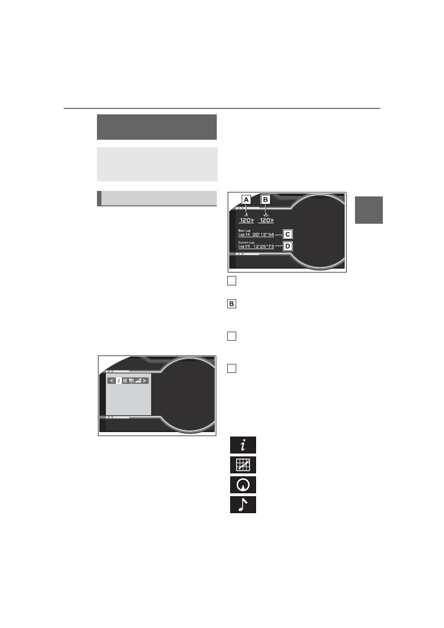
TRACK mode display

Vehicles without EyeSight:
When in TRACK mode, the 
TRACK mode display will 
remain displayed.
Vehicles with EyeSight:
When in TRACK mode, if the 

Pre-Collision Braking System is 
turned off, the TRACK mode 
display will be displayed. 
(

P.189)

Warning or advice pop-up dis-
plays are also displayed in cer-
tain situations.

Engine coolant temperature 
(

P.88)

Engine oil temperature

Displays the engine oil tempera-
ture.

Fastest lap time

Refer to P.97 for the operating 
method.

Current lap time

Refer to P.97 for the operating 
method.

Menu icons

Select a menu icon to display its 
content.

Multi-information dis-

play

The multi-information dis-
play presents the driver with 
a variety of vehicle data.

Displays and menu icons

Driving information 
(

P.94)

Sport information (

P.96)

Navigation system-linked 
display

*

 (

P.98)

Audio system-linked dis-
play (

P.98)

A

C

D

94

2-1. Instrument cluster

*

: Displayed when the navigation 

system of Apple CarPlay or 
Android Auto is operating. For 
details, refer to the “MULTIMEDIA 
OWNER’S MANUAL”.

Liquid crystal display

Small spots or light spots may 

appear on the display. This phenom-

enon is characteristic of liquid crys-

tal displays, and there is no problem 

continuing to use the display.

The multi-information display is 

operated using the meter control 
switches.
For information pertaining to the 
content of each menu icon, refer 
to the explanation of each item 
under the heading of the rele-
vant menu icon.

/

: Select menu icons

/

: Change displayed 

content, scroll up/down the 
screen and move the cursor
Press: Enter
Press and hold: 
Reset/change scale of the 
G-force display
Return to the previous screen

Display items

Press 

 or 

 of the meter 

control switch and select 

Then press 

 or 

 to display 

the following items:

Driving information (page 1)

Driving information (page 2)

Driving information (page 3)

Driving support system 
information display (if 
equipped) (

P.98)

Driving support system 
setting display (

P.98)

Settings display (

P.98)

Warning message display 
(

P.357)

WARNING

The multi-information display 

at low temperatures

Allow the interior of the vehicle to 

warm up before using the liquid 

crystal information display. At 

extremely low temperatures, the 

information display monitor may 

respond slowly, and display 

changes may be delayed.
For example, there is a lag 

between the driver’s shifting and 

the new gear number appearing 

on the display. This lag could 

cause the driver to downshift 

again, causing rapid and exces-

sive engine braking and possibly 

an accident resulting in death or 

injury.

Changing the meter dis-
play

Content of driving infor-
mation

A

C

95

2-1. Instrument cluster

2

Vehicle

 statu

s information an

d in
dicator

s

Driving information (page 4)

Driving information (page 1)

Use the display as a reference.

Voltmeter

Displays the charging voltage.
As voltage displayed may be differ-
ent from the actual battery voltage, 
use the voltmeter as a guideline.

Engine oil temperature 
gauge

Displays the engine oil tempera-
ture.

Driving information (page 2)

Use the display as a reference.

Current fuel consumption

Displays the current rate of fuel 
consumption.

Average fuel consumption

Displays the average fuel con-
sumption since the function was 
reset.

Driving range

Displays the estimated maximum 
distance that can be driven with the 
quantity of fuel remaining.
This distance is computed based 
on your average fuel consumption. 
As a result, the actual distance that 
can be driven may differ from that 
displayed.
When only a small amount of fuel is 
added to the tank, the display may 
not be updated. When refueling, 
turn the engine switch off. If the 
vehicle is refueled without turning 
the engine switch off, the display 
may not be updated.

Driving information (page 3)

Use the display as a reference.

Average vehicle speed

Displays the average vehicle speed 
since display was reset.

Driving time

Displays the cumulative time the 
vehicle has been driven since dis-
play was reset.

Driving distance

Displays the cumulative distance 
the vehicle has been driven since 
display was reset.

Pressing and holding 

 will 

reset the average vehicle 

A

A

C

A

C

96

2-1. Instrument cluster

speed/driving time/driving dis-
tance.

Driving information (page 4)

Displays each tire pressure. 
(

P.315)

Display items

Press 

 or 

 of the meter 

control switch and select 

Then press 

 or 

 to display 

the following items:

G-force

Suitable for confirming current lat-
eral G-forces on the vehicle.

G-force (peak hold function)

Suitable for confirming the size and 
direction of the maximum lateral 
G-forces on the vehicle.

Power and torque curve

Stopwatch

G-force

Displays lateral G-forces on the 
vehicle.
Also displays, around the 
periphery of the G-force display, 
the left and right steering 
amount, accelerator pedal input, 
and brake fluid pressure.
This display is intended for use 
as a guideline. Depending on 
factors such as the road surface 
condition, temperature and vehi-
cle speed, the display may not 
show the actual condition of the 

vehicle.

Acceleration G-force on the 
vehicle
Accelerator pedal input
Brake fluid pressure
Steering amount

Press and hold 

 to change 

the range of the acceleration 
G-force display between 1.0 G 
and 0.5 G.

G-force (peak hold func-
tion)

Displays lateral G-forces on the 
vehicle.
Also displays, around the 
periphery of the G-force display, 
the left and right steering 
amount, accelerator pedal input, 
and brake fluid pressure.
This display is intended for use 
as a guideline. Depending on 
factors such as the road surface 
condition, temperature and vehi-
cle speed, the display may not 
show the actual condition of the 
vehicle.

Sport information

A

C
D

97

2-1. Instrument cluster

2

Vehicle

 statu

s information an

d in
dicator

s

Record of the maximum 
G-forces

Press and hold 

 to reset the 

record of maximum G-forces.

Acceleration G-force on the 
vehicle
Accelerator pedal input
Brake fluid pressure
Steering amount

Power and torque curve

This chart is intended for refer-
ence only and does not show 
the actual engine torque or out-
put.

Power output
Torque
Current engine speed

The vertical bar will slide laterally 
according to the current engine 
speed.

Stopwatch

Measures and displays current 
lap time and previous lap times.

Top screen

Fastest lap time (top screen)

When the timer is reset, “- -’- -”- -” 
will be displayed.

Measurement screen

Fastest lap time (measure-
ment screen)
Current lap time
Total lap time
Past lap times

Records of the 50 most recent lap 
times will be displayed.

Meter control switch opera-
tion guide

Changing between the stop-
watch screens

To change to the measurement 

A

C
D

A

C

A

A

C
D

98

2-1. Instrument cluster

screen: Press 

.

To change to the top screen: Press 

.

Operating the measurement 
screen

 : Start/stop measurement

 : Mark off one lap

 : Reset measured lap times

 : Scroll through the lap 

times

Resetting measured lap times

After stopping the measurement, 
press 

.

To display other content while 
the stopwatch is operating

If the measurement screen is dis-
played, press 

 to display the top 

screen.
Then operate the meter control 
switches to display other content. 
While other items are displayed, 
the measurement will continue but 
the stopwatch cannot be operated.

Select to display the route guid-
ance information.

Select to enable selection of an 
audio source or track on the dis-
play using the meter control 

switches.

Select to display the operational 
status of the Adaptive Cruise 
Control system (

P.190, 207)

The settings of the following 
systems can be changed.

LDW (Lane Departure Warn-
ing) (if equipped)

PCB (Pre-Collision Braking) 
(if equipped)

BSD/RCTA (if equipped)

RAB (Reverse Automatic 
Braking system) (if equipped)

 (Sonar Audible Alarm) (if 

equipped)

SRH (Steering Responsive 
Headlight) (if equipped)

Meter display settings that 
can be changed

Units

Select to change the units of mea-
sure displayed.

Startup Scrn

Navigation system-linked 
display

Audio system-linked dis-
play

Driving support system 
information display (if 
equipped)

Driving support system 
setting display

Settings display

99

2-1. Instrument cluster

2

Vehicle

 s

ta

tu

s information an

d in
dicat

or

s

Select to enable/disable the startup 
screen when the engine switch is 
turned to ON.

GSI (if equipped)

Select to enable/disable the shift 
position indicator and shift-up indi-
cator.

REV. (REV indicator)

• Select to enable/disable the REV 

indicator.

• Select to enable/disable the 

sounding of a buzzer when the 
REV indicator is illuminated.

• Select to set the engine speed at 

which the REV indicator (orange) 
will begin to be displayed.

Vehicle functions and set-
tings that can be changed

P.400

Suspension of the settings dis-

play

Some settings cannot be changed 

while driving. When changing set-

tings, park the vehicle in a safe 

place.

If a warning message is displayed, 

operation of the settings display 

will be suspended.

WARNING

Cautions during setting up 

the display

As the engine needs to be run-

ning during setting up the display, 

ensure that the vehicle is parked 

in a place with adequate ventila-

tion. In a closed area such as a 

garage, exhaust gases including 

harmful carbon monoxide (CO) 

may collect and enter the vehicle. 

This may lead to death or a seri-

ous health hazard.

NOTICE

While setting up the display

To prevent battery discharge, 

ensure that the engine is running 

while setting up the display fea-

tures.

100

2-1. Instrument cluster

101

3

3

Before driv

ing

Before driving

.

3-1. Key information

Keys ............................

102

3-2. Opening, closing and 

locking the doors and 
trunk

Doors ..........................

105

Trunk ...........................

107

Smart key system .......

111

3-3. Adjusting the seats

Front seats ..................

119

Rear seats...................

121

Head restraints............

123

3-4. Adjusting the steering 

wheel and mirrors

Steering wheel ............

125

Inside rear view mirror

..................................

126

Outside rear view mirrors

..................................

127

3-5. Opening, closing the win-

dows

Power windows ...........

129

102

3-1. Key information

3-1.Key information

The following keys are provided 
with the vehicle.

Electronic keys

• Operating the smart key system 

(

P.111)

• Operating the wireless remote 

control function (

P.103)

Mechanical keys
Key number plate

When riding in an aircraft

When bringing an electronic key 

onto an aircraft, make sure you do 

not press any buttons on the elec-

tronic key while inside the aircraft 

cabin. If you are carrying an elec-

tronic key in your bag etc., ensure 

that the buttons are not likely to be 

pressed accidentally. Pressing a 

button may cause the electronic key 

to emit radio waves that could inter-

fere with the operation of the air-

craft.

Electronic key battery depletion

The standard battery life is 1 to 2 

years.

If the battery becomes low, an 

alarm will sound in the cabin and a 

message will be shown on the 

multi-information display when the 

engine is stopped.

To reduce key battery depletion 

when the electronic key is to not 

be used for long periods of time, 

set the electronic key to the bat-

tery-saving mode. (

P.112)

As the electronic key always 

receives radio waves, the battery 

will become depleted even if the 

electronic key is not used. The fol-

lowing symptoms indicate that the 

electronic key battery may be 

depleted. Replace the battery 

when necessary. (

P.328)

• The smart key system or the wire-

less remote control does not oper-

ate.

• The detection area becomes 

smaller.

• The LED indicator on the key sur-

face does not turn on.

To avoid serious deterioration, do 

not leave the electronic key within 

3 ft. (1 m) of the following electri-

cal appliances that produce a 

magnetic field:

• TVs

• Personal computers

• Cellular phones, cordless phones 

and battery chargers

• Recharging cellular phones or 

cordless phones

• Table lamps

• Induction cookers

Replacing the battery

P.328

Confirmation of the registered 

key number

The number of keys already regis-

tered to the vehicle can be con-

firmed. Ask your Toyota dealer for 

details.

Keys

The keys

A

C

NOTICE

To prevent key damage

Do not drop the keys, subject 

them to strong shocks or bend 

them.

103

3-1. Key information

3

Before driv

ing

The electronic keys are 
equipped with the following 
wireless remote control:

Locks the doors (

P.105)

Unlocks the doors (

P.105)

Opens the trunk (

P.110)

Sounds the alarm

Panic mode

When 

 is pressed for longer than 

about one second, an alarm will 

sound intermittently and the vehicle 

lights will flash to deter any person 

from trying to break into or damage 

your vehicle.
To stop the alarm, press any button 

on the electronic key.

Vehicle finder function

When the function is set, a buzzer 

(sounds once) and the emergency 

flashers (flash 3 times) are used to 

inform the driver of the vehicle’s 

location.

Press 

 3 times within 5 seconds 

while within a circumference of 

approximately 30 ft. (10 m) from of 

the vehicle.
However, if the interval between the 

3 presses is short, the system may 

not be activated.

NOTICE

Do not expose the keys to high 

temperatures for long periods of 

time.

Do not get the keys wet or wash 

them in an ultrasonic washer 

etc.

Do not attach metallic or mag-

netic materials to the keys or 

place the keys close to such 

materials.

Do not disassemble the keys.

Do not attach a sticker or any-

thing else to the surface of the 

electronic key.

Do not place the keys near 

objects that produce magnetic 

fields, such as TVs, audio sys-

tems and induction cookers.

Carrying the electronic key 

on your person

Carry the electronic key 3.9 in. 

(10 cm) or more away from elec-

tric appliances that are turned on. 

Radio waves emitted from electric 

appliances within 3.9 in. (10 cm) 

of the electronic key may interfere 

with the key, causing the key to 

not function properly.

In case of a smart key system 

malfunction or other 

key-related problems

P.370

When an electronic key is lost

P.369

Wireless remote control

A

C

D

104

3-1. Key information

Customization

Some functions can be customized. 

(

P.400)

To take out the mechanical key, 
push the release button and 
take the key out.

The mechanical key can only be 
inserted in one direction, as the key 
only has grooves on one side. If the 
key cannot be inserted in a lock cyl-
inder, turn it over and re-attempt to 
insert it.
After using the mechanical key, 
store it in the electronic key. Carry 
the mechanical key together with 
the electronic key. If the electronic 
key battery is depleted or the entry 
function does not operate properly, 
you will need the mechanical key. 
(

P.370)

If you lose your mechanical 

keys

P.369

Using the mechanical key

105

3-2. Opening, closing and locking the doors and trunk

3

Before driv

ing

3-2.Opening, closing and locking the doors and trunk

Smart key system

Carry the electronic key to 
enable this function.

1

Grip the driver’s door handle 
to unlock the door. Grip the 
passenger’s door handle to 
unlock all the doors.

*

Make sure to touch the sensor on 
the back of the handle.
The doors cannot be unlocked for 3 
seconds after the doors are locked.

*

: The door unlock settings can be 

changed.

2

Touch the lock sensor (inden-
tation on the side of the door 
handle) to lock the doors.

Check that the door is securely 
locked.

Wireless remote control

1

Locks both side doors

Check that the door is securely 
locked.

2

Unlocks both side doors

Pressing the button unlocks the 
driver’s door. Pressing the button 
again within 3 seconds unlocks the 
other door.

Side window open/close func-

tion linked to door operation

In order to make opening and clos-

ing the doors easier, completely 

closed windows are linked to door 

operations. Therefore, when a door 

is opened, its window opens slightly. 

When a door is closed, its window 

closes completely.
However, if the battery has dis-

charged or is disconnected, this 

function will not operate. (

P.374)

Operation signals

A buzzer sounds and the emer-

gency flashers flash to indicate that 

the doors have been 

locked/unlocked. (Locked: once; 

Unlocked: twice)

When the door cannot be 

locked by the lock sensor on 

the surface of the door handle

If the doors cannot be locked by 

touching the lock sensor with a fin-

ger, touch the lock sensor with the 

palm of your hand.
If you are wearing gloves, remove 

Doors

Unlocking and locking the 
doors from the outside

106

3-2. Opening, closing and locking the doors and trunk

them.

Door lock buzzer

If an attempt to lock the doors using 

the entry function or wireless remote 

control is made when a door is not 

fully closed, a buzzer will sound 

continuously for 5 seconds. Fully 

close the door to stop the buzzer, 

and lock the doors again.

Alarm

Locking the doors will set the alarm 

system. (

P.81)

Conditions affecting the opera-

tion of the smart key system or 

wireless remote control

P.112

If the smart key system or the 

wireless remote control does 

not operate properly

Use the mechanical key and/or 

inside lock buttons to lock and 

unlock the doors. (

P.370)

Replace the key battery with a new 

one if it is depleted. (

P.328)

If the battery is discharged

The doors cannot be locked and 

unlocked using the smart key sys-

tem or wireless remote control. Lock 

or unlock the doors using the 

mechanical key. (

P.370)

Customization

Some functions can be customized. 

(

P.400)

Door lock switches (to 
lock/unlock)

1

Locks both side doors

2

Unlocks both side doors

WARNING

To prevent an accident

Ensure that both side doors are 

properly closed and locked while 

driving the vehicle.

Failure to do so may result in a 

door opening and an occupant 

being thrown out of the vehicle, 

resulting in death or serious injury.

When opening or closing a 

door

Check the surroundings of the 

vehicle such as whether the vehi-

cle is on an incline, whether there 

is enough space for a door to 

open and whether a strong wind 

is blowing. When opening or clos-

ing the door, hold the door handle 

tightly to prepare for any unpre-

dictable movement.

Side window open/close func-

tion linked to door operation

Do not hold the upper edge of the 

side window when you close the 

door. Otherwise, your fingers or 

hand may be caught in the win-

dow.

Unlocking and locking the 
doors from the inside

107

3-2. Opening, closing and locking the doors and trunk

3

Before driv

ing

Inside lock buttons (to 
lock/unlock)

1

Locks the door

2

Unlocks the door

Locking the doors from the out-

side without a key

1

Move the inside lock button to 

the lock position.

2

Close the door.

The door cannot be locked if the 

engine switch is in ACC or ON, or 

the electronic key is left inside the 

vehicle. However, the key may not 

be detected correctly and the door 

may be locked.

Door lock prevention function

This function prevents the doors 

from being locked if an electronic 

key is left inside the vehicle.

Customization

Some functions can be customized. 

(

P.400)

Trunk

The trunk can be opened 
using the trunk opener 
switch, entry function or 
wireless remote control.

WARNING

Observe the following precau-

tions.

Failure to do so may result in 

death or serious injury.

Before driving

Make sure that the trunk lid is 

closed before driving. If not fully 

closed, while driving, it may 

open unexpectedly, hit near-by 

objects, or luggage may fall out, 

possibly leading to an accident.

Also, exhaust gasses may enter 

the vehicle, possibly leading to 

death or a serious health haz-

ard.

Do not allow children to play in 

the trunk.

If a child is accidentally locked 

in the trunk, they could suffer 

from heat exhaustion, suffoca-

tion or other injuries.

Do not allow a child to open or 

close the trunk lid.

Doing so may cause the trunk 

lid to open unexpectedly, or 

cause the child’s hands, head, 

or neck to be caught by the 

closing trunk lid.

Important points while driving

Never let anyone sit in the trunk. 

In the event of sudden braking or 

a collision, they are susceptible to 

death or serious injury.

108

3-2. Opening, closing and locking the doors and trunk

WARNING

Using the trunk

Observe the following precau-

tions.

Failure to do so may cause parts 

of the body to be caught, resulting 

in serious injury.

Remove any heavy loads, such 

as snow and ice, from the trunk 

lid before opening it. Failure to 

do so may cause the trunk lid to 

suddenly shut again after it is 

opened.

Be careful not to come into con-

tact with the exhaust gasses 

when opening or closing the 

trunk. If the engine is running, 

there is a risk of being burned 

by the exhaust gasses.

When opening or closing the 

trunk lid, thoroughly check to 

make sure the surrounding area 

is safe.

If anyone is in the vicinity, make 

sure they are safe and let them 

know that the trunk is about to 

open or close.

Use caution when opening or 

closing the trunk lid in windy 

weather as it may move 

abruptly in strong wind.

The trunk lid may suddenly shut 

if it is not opened fully. It is more 

difficult to open or close the 

trunk lid on an incline than on a 

level surface, so beware of the 

trunk lid unexpectedly opening 

or closing by itself. Make sure 

that the trunk lid is fully open 

and secure before using the 

trunk.

When closing the trunk lid, take 

extra care to prevent your fin-

gers etc. from being caught.

When closing the trunk lid, 

make sure to press it lightly on 

its outer surface.

Do not attach any accessories 

other than genuine Toyota parts 

to the trunk lid. Such additional 

weight on the trunk lid may 

cause the lid to suddenly shut 

again after it is opened.

Trunk lid damper stays

Do not pull on or disassemble the 

trunk lid damper stays, or dispose 

of them in a fire. Illustrations on 

the trunk lid damper stays indicate 

the following:

: Do not pull


Content      ..     4      5      6      7     ..