Toyota Highlander (2022 year). Manual in english - page 27
 

  Index      Toyota     Toyota Highlander (2022 year). Manual in english


Search            copyright infringement  


Content      ..     25      26      27      28     ..


Toyota Highlander (2022 year). Manual in english - page 27


433

6-3. Do-it-yourself maintenance

6

Maintena

nce
 a

nd ca

re

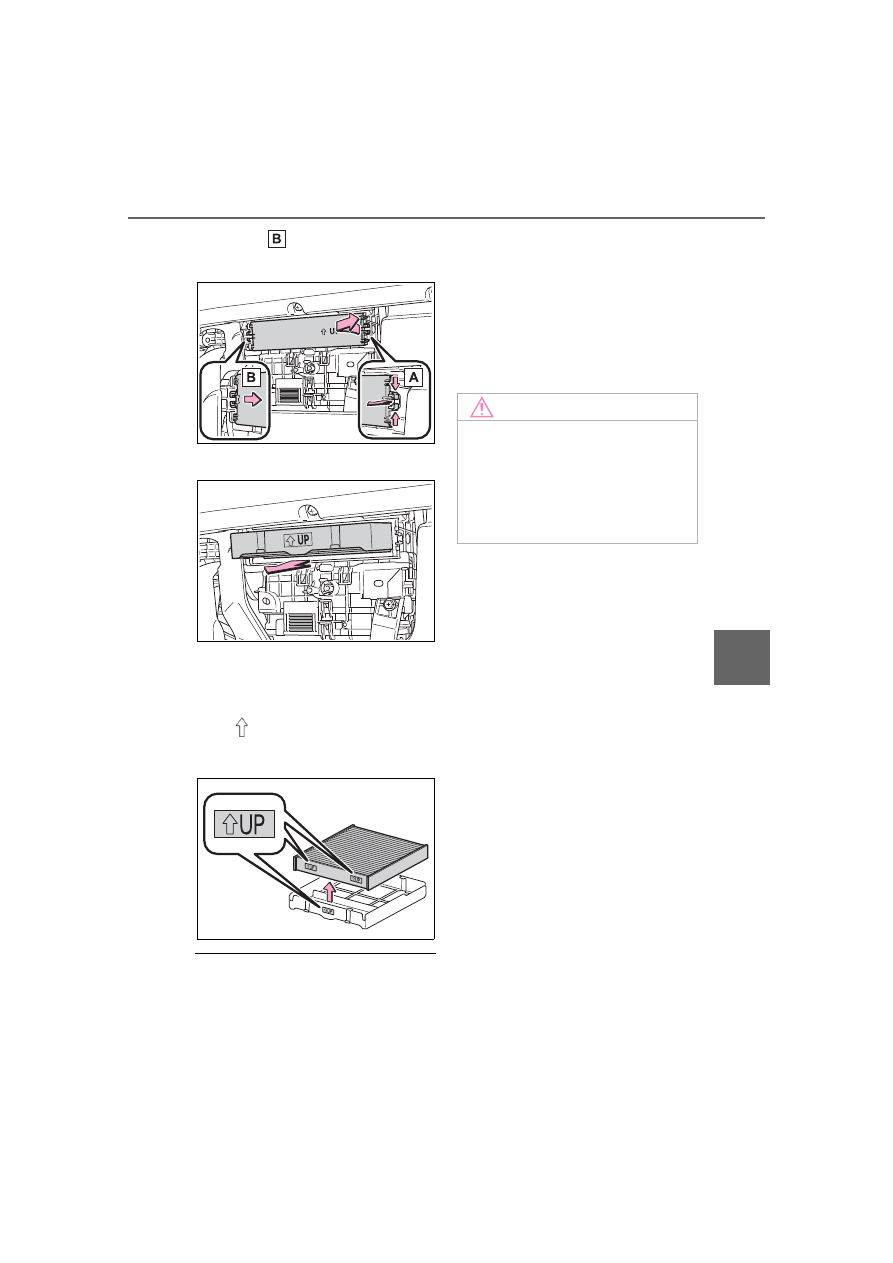
claws ( ), and remove the 
filter cover.

5

Remove the filter case.

6

Remove the air conditioning 
filter from the filter case and 
replace it with a new one.

The “

UP” marks shown on the 

filter and the filter case should be 

pointing up.

Checking interval

Inspect and replace the air condi-

tioning filter according to the mainte-

nance schedule. In dusty areas or 

areas with heavy traffic flow, early 

replacement may be required. (For 

scheduled maintenance information, 

please refer to the “Owner’s Manual 

Supplement” or “Scheduled Mainte-

nance Guide”.)

If air flow from the vents 

decreases dramatically

The filter may be clogged. Check 

the filter and replace if necessary.

NOTICE

When using the air condition-

ing system

Make sure that a filter is always 

installed.

Using the air conditioning system 

without a filter may cause damage 

to the system.

434

6-3. Do-it-yourself maintenance

If the electronic key battery is 

depleted

The following symptoms may occur:

The smart key system and wire-

less remote control will not func-

tion properly.

The operational range will be 

reduced.

Flathead screwdriver

Small flathead screwdriver

Lithium battery CR2032

Use a CR2032 lithium battery

Batteries can be purchased at 

your Toyota dealer, local electrical 

appliance shops or camera stores.

Replace only with the same or 

equivalent type recommended by 

the manufacturer.

Dispose of used batteries accord-

ing to the local laws.

1

Release the lock and remove 
the mechanical key.

2

Remove the key cover.

To prevent damage to the key, 

cover the tip of the flathead screw-

driver with a rag.

3

Remove the depleted battery.

When removing the cover, the elec-

tronic key module may stick to the 

cover and the battery may not be 

visible. In this case, remove the 

electronic key module in order to 

remove the battery.
When removing the battery, use a 

screwdriver of an appropriate size. 

Insert a new battery with the “+” ter-

Electronic key battery

Replace the battery with a 
new one if it is depleted.

You will need the follow-
ing items:

Replacing the battery

435

6-3. Do-it-yourself maintenance

6

Maintena

nce
 a

nd ca

re

minal facing up.

WARNING

Battery precautions

Observe the following precau-

tions. Failure to do so may result 

in death or serious injury.

Do not swallow the battery. 

Doing so may cause chemical 

burns.

A coin battery or button battery 

is used in the electronic key. If a 

battery is swallowed, it may 

cause severe chemical burns in 

as little as 2 hours and may 

result in death or serious injury.

Keep away new and removed 

batteries from children.

If the cover cannot be firmly 

closed, stop using the electronic 

key and stow the key in the 

place where children cannot 

reach, and then contact your 

Toyota dealer.

If you accidentally swallow a 

battery or put a battery into a 

part of your body, get emer-

gency medical attention imme-

diately.

To prevent battery explosion 

or leakage of flammable liq-

uid or gas

Replace the battery with a new 

battery of the same type. If a 

wrong type of battery is used, it 

may explode.

Do not expose batteries to 

extremely low pressure due to 

high altitude or extremely high 

temperatures.

Do not burn, break or cut a bat-

tery.

NOTICE

For normal operation after 

replacing the battery

Observe the following precautions 

to prevent accidents:

Always work with dry hands.

Moisture may cause the battery 

to rust.

Do not touch or move any other 

component inside the remote 

control.

Do not bend either of the battery 

terminals.

436

6-3. Do-it-yourself maintenance

1

Turn the engine switch off.

2

Open the fuse box cover.

Engine compartment: type A 
fuse box (if equipped)

Push the tab in and lift the lid off.

Engine compartment: type B 
fuse box

Push the tab in and lift the lid off.

Under the driver’s side instru-
ment panel

Remove the lid.
Make sure to push the claw when 
removing/installing the lid.

3

Remove the fuse.

Only type A fuse can be removed 

using the pullout tool.

4

Check if the fuse is blown.

Replace the blown fuse with a new 

fuse of an appropriate amperage 

rating. The amperage rating can be 

found on the fuse box lid.

Type A

Checking and replac-

ing fuses

If any of the electrical com-
ponents do not operate, a 
fuse may have blown. If this 
happens, check and replace 
the fuses as necessary.

Checking and replacing 
fuses

437

6-3. Do-it-yourself maintenance

6

Maintena

nce
 a

nd ca

re

Normal fuse
Blown fuse

Type B

Normal fuse
Blown fuse

Type C

Normal fuse
Blown fuse

After a fuse is replaced

If the lights do not turn on even 

after the fuse has been replaced, 

a bulb may need replacement. 

(

P.439)

If the replaced fuse blows again, 

have the vehicle inspected by 

your Toyota dealer.

If there is an overload in a cir-

cuit

The fuses are designed to blow, pro-

tecting the wiring harness from 

damage.

When replacing light bulbs

Toyota recommends that you use 

genuine Toyota products designed 

for this vehicle. Because certain 

bulbs are connected to circuits 

designed to prevent overload, 

non-genuine parts or parts not 

designed for this vehicle may be 

unusable.

WARNING

To prevent system break-

downs and vehicle fire

Observe the following precau-

tions.

Failure to do so may cause dam-

age to the vehicle, and possibly a 

fire or injury.

Never use a fuse of a higher 

amperage rating than that indi-

cated, or use any other object in 

place of a fuse.

Always use a genuine Toyota 

fuse or equivalent.

Never replace a fuse with a 

wire, even as a temporary fix.

Do not modify the fuses or fuse 

boxes.

NOTICE

Before replacing fuses

Have the cause of electrical over-

load determined and repaired by 

your Toyota dealer as soon as 

possible.

438

6-3. Do-it-yourself maintenance

Adjustment bolt A
Adjustment bolt B

Make sure the vehicle has a 
full tank of gasoline and the 
area around the headlight is 
not deformed.

Park the vehicle on level 
ground.

Make sure the tire inflation 
pressure is at the specified 
level.

Have someone sit in the 
driver’s seat.

Bounce the vehicle several 
times.

1

Using a Phillips-head screw-
driver, turn bolt A in either 
direction.

Remember the turning direction 

and the number of turns.

2

Turn bolt B the same number 
of turns and in the same 
direction as step 

1

.

If the headlight cannot be adjusted 

using this procedure, take the vehi-

cle to your Toyota dealer to adjust 

the headlight aim.

Headlight aim

Vertical movement adjust-
ing bolts

Before checking the head-
light aim

Adjusting the headlight 
aim

439

6-3. Do-it-yourself maintenance

6

Maintena

nce
 a

nd ca

re

Check the wattage of the light 
bulb to be replaced. (

P.507)

P.526

Front (type A)

Front turn signal lights/park-

ing lights
Front side marker lights

Front (type B)

Front turn signal lights
Front side marker lights

Front (type C)

Front turn signal lights/park-
ing lights
Front side marker lights

Rear

Rear turn signal lights

Light bulbs

You may replace the follow-
ing bulbs by yourself. The 
difficulty level of replace-
ment varies depending on 
the bulb. If necessary bulb 
replacement seems difficult 
to perform, contact your 
Toyota dealer.

For more information about 
replacing other light bulbs, 
contact your Toyota dealer.

Preparing for light bulb 
replacement

Turning off the power 
back door main switch (if 
equipped)

Bulb locations

440

6-3. Do-it-yourself maintenance

Back-up lights
License plate lights

Lights that need to be 
replaced by your Toyota 
dealer

Headlight low beams

Headlight high beams

Daytime running lights (types 
A and C)

Daytime running lights/park-
ing lights (type B)

Front fog lights (if equipped)

Side turn signal lights

Tail lights/stop lights

Rear side marker lights

Tail lights

High mounted stoplight

Outer foot lights (if equipped)

LED lights

The lights other than the following 

lights each consist of a number of 

LEDs. If any of the LEDs burn out, 

take your vehicle to your Toyota 

dealer to have the light replaced.

Front turn signal lights/parking 

lights (types A and C)

Front turn signal lights (type B)

Front side marker lights

Rear turn signal lights

Back-up lights

License plate lights

Condensation build-up on the 

inside of the lens

Temporary condensation build-up 

on the inside of the light lens does 

not indicate a malfunction. Contact 

your Toyota dealer for more informa-

tion in the following situations:

Large drops of water have built up 

on the inside of the lens.

Water has built up inside the light.

When replacing light bulbs

P.437

Front turn signal 
lights/parking lights (types 
A and C) and front turn sig-
nal lights (type B)

1

Turn the bulb base counter-
clockwise and remove it.

2

Remove the light bulb.

3

Install a new light bulb, and 
then install the bulb base to 
the light unit by inserting it 
and turning the bulb base 
clockwise.

After installing the bulb base, wig-

gle it lightly to make sure it is 

Replacing light bulbs

441

6-3. Do-it-yourself maintenance

6

Maintena

nce
 a

nd ca

re

securely installed and turn the lights 

and turn signal lights on to visually 

check that there is no light leaking 

from between the bulb base and 

light unit.

Front side marker lights

1

Turn the bulb base counter-
clockwise and remove it.

2

Remove the light bulb.

3

Install a new light bulb, and 
then install the bulb base to 
the light unit by inserting it 
and turning the bulb base 
clockwise.

After installing the bulb base, wig-

gle it lightly to make sure it is 

securely installed and turn the lights 

on to visually check that there is no 

light leaking from between the bulb 

base and light unit.

Rear turn signal lights

1

Open the back door and 
using a flathead screwdriver, 
remove the cover.

To prevent damage to the vehicle, 

wrap the tip of the flathead screw-

driver with tape, etc.

2

Remove the securing 2 
screws and light unit.

Remove the light unit by pulling it 

straight back from the rear of the 

442

6-3. Do-it-yourself maintenance

vehicle.

3

Disconnect the wire harness.

4

Turn the bulb base counter-
clockwise and remove it.

5

Remove the light bulb.

6

Install a new light bulb, and 
then install the bulb base to 
the light unit by inserting it 
and turning it clockwise.

After installing the bulb base, wig-

gle it lightly to make sure it is 

securely installed and turn on the 

turn signal lights to visually check 

that there is no light leaking from 

between the bulb base and light 

unit.

7

Install the light unit.

Align the 2 guides and push the 

light unit toward the front of the 

vehicle to install it.

443

6-3. Do-it-yourself maintenance

6

Maintena

nce
 a

nd ca

re

8

Install the 2 screws.

9

Install the cover.

Back-up lights

1

Open the back door and 
remove the cover.

Using a flathead screwdriver, 

remove the cover.
To prevent damage to the vehicle, 

wrap the tip of the flathead screw-

driver with tape, etc.

2

Turn the bulb base counter-
clockwise and remove it.

3

Remove the light bulb.

4

Install a new light bulb, and 
then install the bulb base to 
the light unit by inserting it 
and turning it clockwise.

After installing the bulb base, wig-

gle it lightly to make sure it is 

securely installed and turn on the 

back-up lights to visually check that 

there is no light leaking from 

between the bulb base and light 

unit.

5

Install the cover.

444

6-3. Do-it-yourself maintenance

Align the tabs of the cover with the 

grooves and install the cover.

License plate lights

1

Remove the cover.

Using a flathead screwdriver, 

remove the cover.
To prevent damage to the vehicle, 

wrap the tip of the flathead screw-

driver with tape, etc.

2

Remove the lens.

Lens
Hook

1

Insert a small flathead screw-
driver, etc. into either the 
right or left hole of the lens.

2

Push the screwdriver side-
ways in the direction of the 
arrow shown in the illustra-
tion, disengage the hook, and 
then remove the lens.

To prevent damage to the vehicle, 
wrap the tip of the screwdriver with 
tape, etc.

445

6-3. Do-it-yourself maintenance

6

Maintena

nce
 a

nd ca

re

3

Remove the light bulb.

4

Install a new light bulb.

5

Install the lens.

Hooks

1

Fit the lens into either the 

right or left hooks.

2

Push the lens into place.

After installation, confirm that the 
lens is properly installed by gently 
pulling it.

6

Install the cover.

WARNING

To prevent injury

Before performing any light bulb 

replacement procedure, be sure 

to turn the engine switch off. Fail-

ure to do so may result in burns 

from hot components or a part of 

your body may get caught on an 

operating component, possibly 

causing serious injury.

Replacing light bulbs

Turn off the lights. Do not 

attempt to replace the bulb 

immediately after turning off the 

lights.The bulbs become very 

hot and may cause burns.

446

6-3. Do-it-yourself maintenance

WARNING

Do not touch the glass portion 

of the light bulb with bare 

hands. When it is unavoidable 

to hold the glass portion, use 

and hold with a clean dry cloth 

to avoid getting moisture and 

oils on the bulb. Also, if the bulb 

is scratched or dropped, it may 

blow out or crack.

Fully install light bulbs and any 

parts used to secure them. Fail-

ure to do so may result in heat 

damage, fire, or water entering 

the light unit. This may damage 

the lights or cause condensa-

tion to build up on the lens.

Do not attempt to repair or dis-

assemble light bulbs, connec-

tors, electric circuits or 

component parts.

Doing so may result in death or 

serious injury due to electric 

shock.

To prevent damage or fire

Make sure bulbs are fully 

seated and locked.

Check the wattage of the bulb 

before installing to prevent heat 

damage.

447

7

7

Whe

n tr

ouble

 ar

ises

When trouble arises

.

7-1. Essential information

Emergency flashers ....

448

If your vehicle has to be 

stopped in an emergency

..................................

448

If the vehicle is submerged 

or water on the road is ris-
ing .............................

449

7-2. Steps to take in an emer-

gency

If your vehicle needs to be 

towed.........................

451

If you think something is 

wrong ........................

454

Fuel pump shut off system

..................................

455

If a warning light turns on or 

a warning buzzer sounds

..................................

456

If a warning message is dis-

played........................

467

If you have a flat tire....

471

If the engine will not start

..................................

485

If you lose your keys ...

486

If the fuel filler door cannot 

be opened .................

487

If the electronic key does 

not operate properly ..

488

If the vehicle battery is dis-

charged .....................

490

If your vehicle overheats

..................................

494

If the vehicle becomes stuck

..................................

496

448

7-1. Essential information

7-1.Essential information

Press the switch.

All the turn signal lights will flash. 
To turn them off, press the switch 
once again.

Emergency flashers

If the emergency flashers are 

used for a long time while the 

engine is not operating, the bat-

tery may discharge.

If any of the SRS airbags deploy 

(inflate) or in the event of a strong 

rear impact, the emergency flash-

ers will turn on automatically. 

The emergency flashers will turn 

off automatically after operating 

for approximately 20 minutes. To 

manually turn the emergency 

flashers off, press the switch 

twice. 

(The emergency flashers may not 

turn on automatically depending 

on the force of the impact and 

conditions of the collision.)

1

Steadily step on the brake 
pedal with both feet and 
firmly depress it.

Do not pump the brake pedal 

repeatedly as this will increase the 

effort required to slow the vehicle.

2

Shift the shift lever to N.

If the shift lever is shifted to N

3

After slowing down, stop the 
vehicle in a safe place by the 
road.

4

Stop the engine.

If the shift lever cannot be 
shifted to N

3

Keep depressing the brake 
pedal with both feet to reduce 
vehicle speed as much as 
possible.

4

To stop the engine, press and 
hold the engine switch for 2 
consecutive seconds or 

Emergency flashers

The emergency flashers are 
used to warn other drivers 
when the vehicle has to be 
stopped on the road due to 
a breakdown, etc.

Operating instructions

If your vehicle has to 

be stopped in an emer-

gency

Only in an emergency, such 
as if it becomes impossible 
to stop the vehicle in the 
normal way, stop the vehicle 
using the following proce-
dure:

Stopping the vehicle


Content      ..     25      26      27      28     ..