Toyota Hilux (2022 year). Manual in english - page 9

4-2. Driving procedures
243
6-speed transmission
4WD models (front-wheel drive control switch in H2 or H4):
km/h (mph)
Maximum speed
Shift position
1
2
3
4
5
113
163
170
205R16C tires
34 (21)
67 (41)
(70)
(101)
(105)
116
167
170
225/70R17C tires
35 (21)
69 (42)
(72)
(103)
(105)
265/65R17, 265/60R18
118
170
170
36 (22)
70 (43)
tires
(73)
(105)
(105)
4WD models (front-wheel drive control switch in L4):
km/h (mph)
4
Maximum speed
Shift position
1
2
3
4
5
205R16C tires
13 (8)
26 (16)
44 (27)
64 (39)
82 (50)
225/70R17C tires
14 (8)
27 (16)
45 (27)
65 (40)
84 (52)
265/65R17 tires
14 (8)
27 (16)
46 (28)
67 (41)
86 (53)
265/60R18 tires
14 (8)
28 (17)
46 (28)
67 (41)
86 (53)
Pre Runner:
km/h (mph)
Maximum speed
Shift position
1
2
3
4
5
116
167
175
225/70R17C tires
35 (21)
69 (42)
(72)
(103)
(108)
118
171
175
265/60R18 tires
36 (22)
70 (43)
(73)
(106)
(108)
118
170
175
265/65R17 tires
36 (22)
70 (43)
(73)
(105)
(108)
244
4-2. Driving procedures
Q Operation of the air conditioning system in Eco drive mode (vehicles
with automatic air conditioning system)
Eco drive mode controls the heating/cooling operations and fan speed of the
air conditioning system to enhance fuel efficiency (P. 446). To improve air
conditioning performance, adjust the fan speed or turn off Eco drive mode.
Q Deactivation of the driving mode
O Eco drive mode will not be canceled until the “ECO” button is pressed, even
if the engine is turned off after driving in Eco drive mode.
OPower mode will be canceled if the engine is turned off after driving in power
mode.
ODriving mode will be canceled if the transfer mode is shifted to L4 while the
driving mode is in other than normal mode. (if equipped)
Q Reverse warning buzzer (6-speed transmission)
A buzzer will sound to alert the driver if the shift lever is shifted to the R posi-
tion.
Q Operation of iMT
O When the clutch pedal is depressed and the shift lever is moved to a posi-
tion, iMT controls the engine speed to be optimal for changing the shift posi-
tion. However, iMT stops operating before the shift position is changed if the
clutch pedal is not released for a while, and the engine speed cannot be
controlled. To operate iMT again, depress the clutch pedal and operate the
shift lever.
O The engine speed may be increased when the clutch pedal is depressed,
however, this does not indicate a malfunction.
Q When iMT does not operate
In the following situations, iMT may not operate. However, this does not indi-
cate a malfunction.
OThe shift lever is not operated for a long time after the clutch pedal is
depressed.
O The vehicle moves for a while after the shift lever is shifted to N and the
clutch pedal is released, and then the clutch pedal is depressed and the
shift lever is moved to a position.
OThe clutch pedal is not completely released and depressed again.
OThe clutch pedal is not fully depressed.
Q If the warning message for iMT is shown on the multi-information dis-
play
iMT may be malfunctioning and the function is disabled. Have the vehicle
inspected at any authorized Toyota retailer or Toyota authorized repairer, or
any reliable repairer as soon as possible.
4-2. Driving procedures
245
WARNING
Q Limitations of the iMT
iMT is not a system that prevents shift lever operation error or engine over-
revving. Depending on the situation, iMT may not operate normally and the
shift position may not be changed smoothly. Overly relying on iMT may
cause an unexpected accident.
NOTICE
Q To prevent damage to the vehicle
O Shift the shift lever to R only when the vehicle is stationary.
ODo not rest your hand on or hold the shift lever any time other than when
shifting.
O In order not to cause the engine to overrev, make sure to only shift gears
sequentially.
4
ODo not release the clutch pedal suddenly, as doing so may cause damage
to the clutch or transmission.
246
4-2. Driving procedures
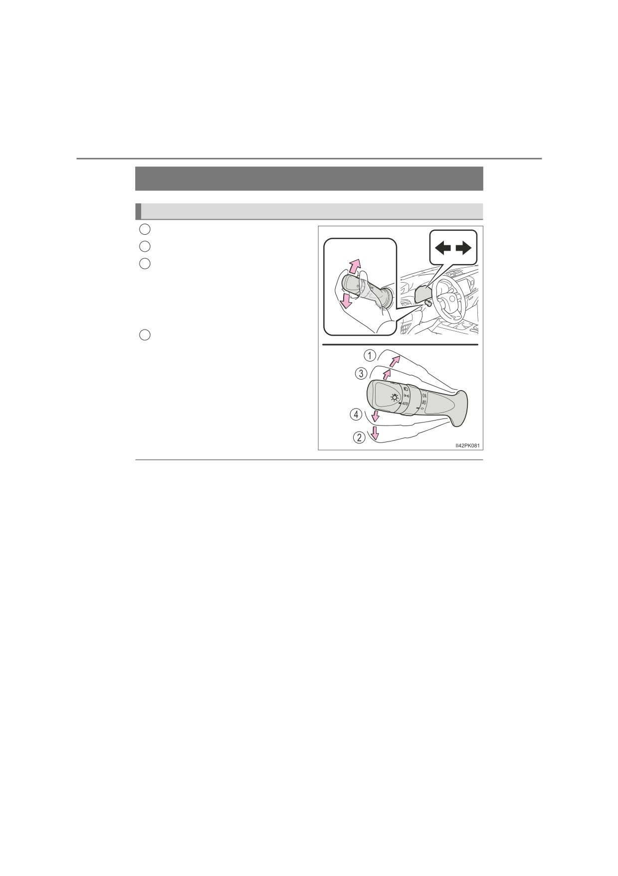
Turn signal lever
Operating instructions
1
Right turn
2
Left turn
3
Lane change to the right (move
the lever partway and release
it)
The right hand signals will flash 3
times.
4
Lane change to the left (move
the lever partway and release
it)
The left hand signals will flash 3
times.
Q Turn signals can be operated when
Vehicles without smart entry & start system
The engine switch is in the “ON” position.
Vehicles with smart entry & start system
The engine switch is in IGNITION ON mode.
Q If the indicator flashes faster than usual
Check that a light bulb in the front or rear turn signal lights has not burned
out.
Q If the turn signals stop flashing before a lane change has been per-
formed
Operate the lever again.
Q To discontinue flashing of the turn signals during a lane change
Operate the lever in the opposite direction.
Q Customization
The number of times the turn signals flash during a lane change can be
changed.
(Customizable features: P. 646)
4-2. Driving procedures
247
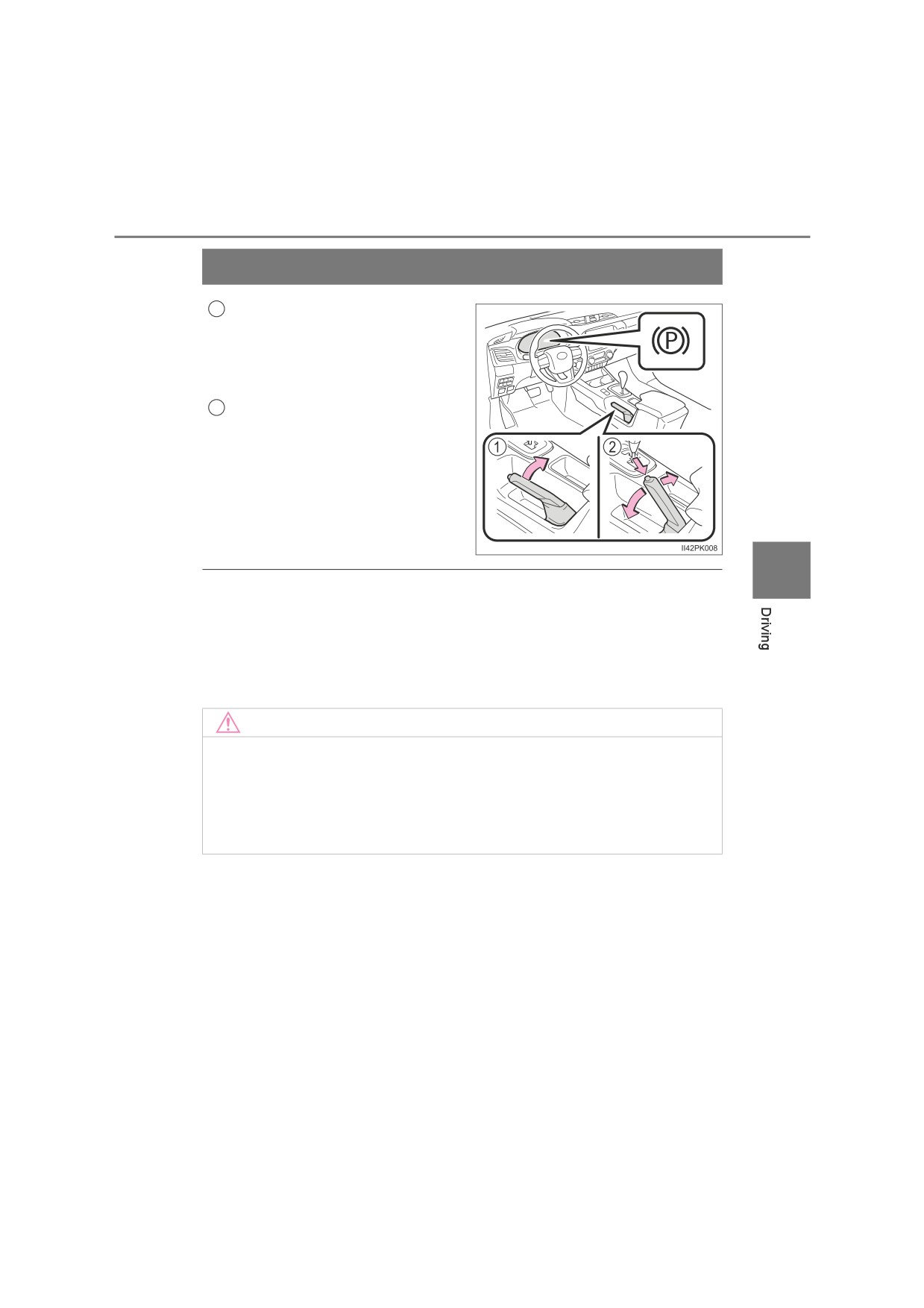
Parking brake
Sets the parking brake
1
Fully pull the parking brake while
depressing the brake pedal.
At this time, the parking brake indi-
cator light will come on.
Releases the parking brake
2
Slightly raise the lever and lower it
completely while pressing the but-
ton.
At this time, the parking brake indi-
cator light will go off.
4
Q Parking the vehicle
P. 193
Q Parking brake engaged warning buzzer
P. 571
Q Usage in winter time
P. 374
NOTICE
Q Before driving
Fully release the parking brake.
Driving the vehicle with the parking brake set will lead to brake components
overheating, which may affect braking performance and increase brake
wear.
248
4-3. Operating the lights and wipers
Headlight switch
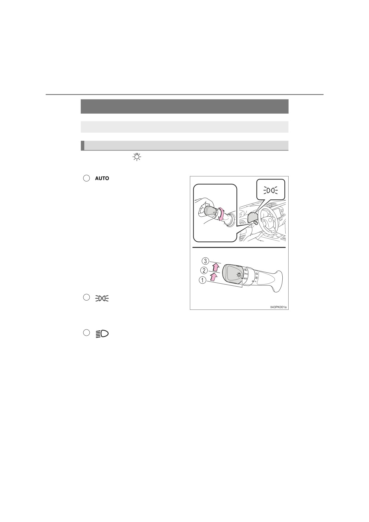
The headlights can be operated manually or automatically.
Operating instructions
Operating the
switch turns on the lights as follows:
Type A
1
The headlights, front posi-
tion, tail, license plate,
instrument panel lights,
and daytime running
lights
(if equipped) (P.
252) turn on and off auto-
matically
(when the
engine switch is in the
“ON” position
[vehicles
without smart
entry &
start system] or IGNI-
TION ON mode [vehicles
with smart entry & start
system]).
2
The front position, tail,
license plate and instru-
ment panel lights turn
on.
3
The headlights and all lights listed above turn on.
4-3. Operating the lights and wipers
249
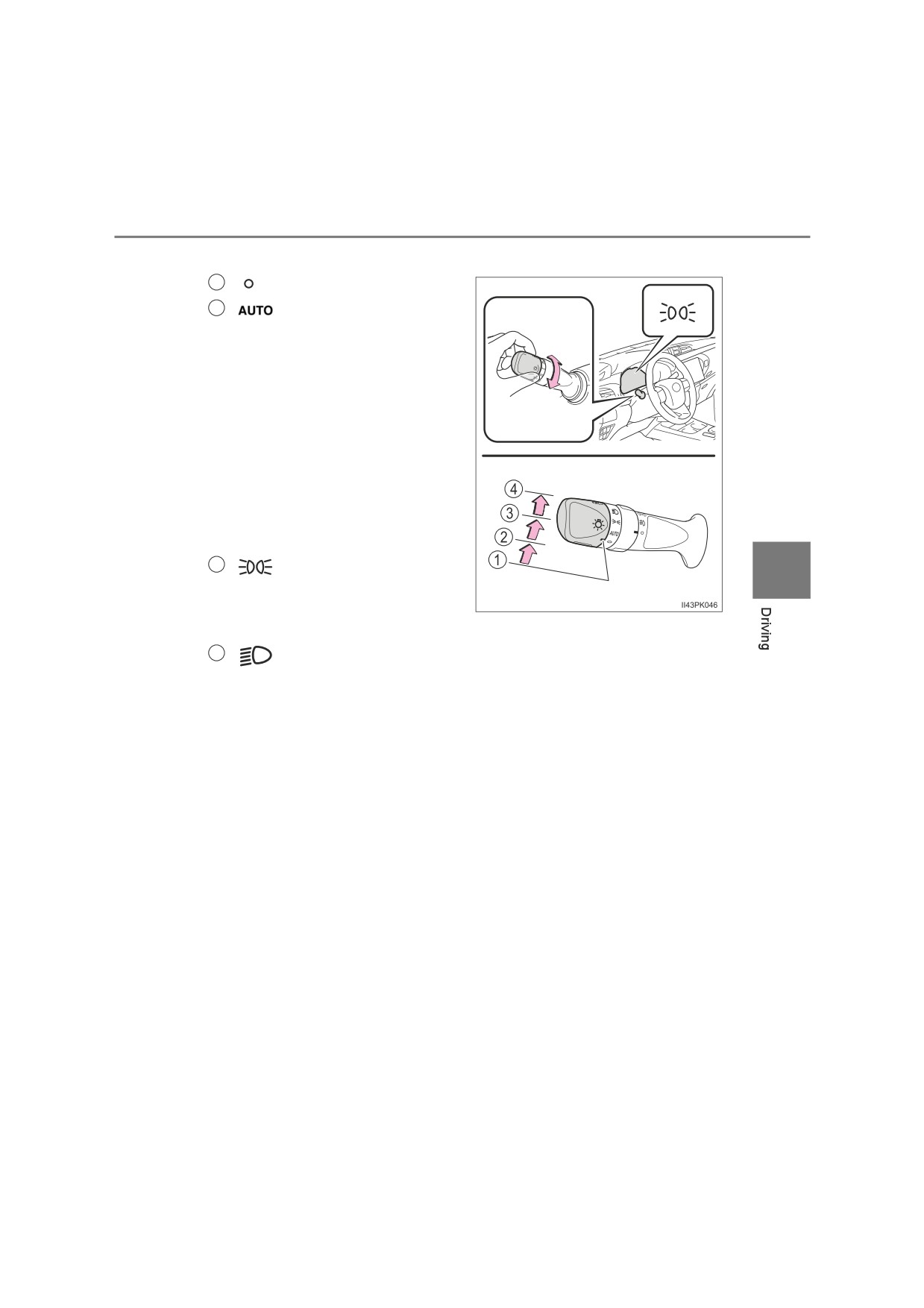
Type B
1
Off.
2
The headlights, front
(if equipped)
position, tail, license
plate and instrument
panel lights turn on and
off automatically
(when
the engine switch is in
the “ON” position [vehi-
cles without smart entry
& start system] or IGNI-
TION ON mode [vehi-
cles with smart entry &
start system]).
3
The front position, tail,
4
license plate and instru-
ment panel lights turn
on.
4
The headlights and all lights listed above turn on.
250
4-3. Operating the lights and wipers
Turning on the high beam headlights
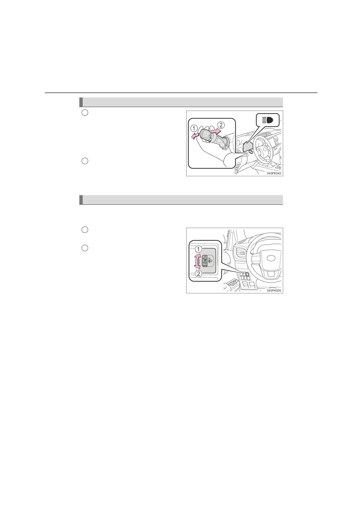
With the headlights on, push
1
the lever away from you to turn
on the high beams.
Pull the lever toward you to the
center position to turn the high
beams off.
Pull the lever toward you and
2
release it to flash the high
beams once.
You can flash the high beams with the headlights on or off.
Manual headlight leveling dial (if equipped)
The level of the headlights can be adjusted according to the number
of passengers and the loading condition of the vehicle.
Raises the level of the head-
1
lights
2
Lowers the level of
the head-
lights
4-3. Operating the lights and wipers
251
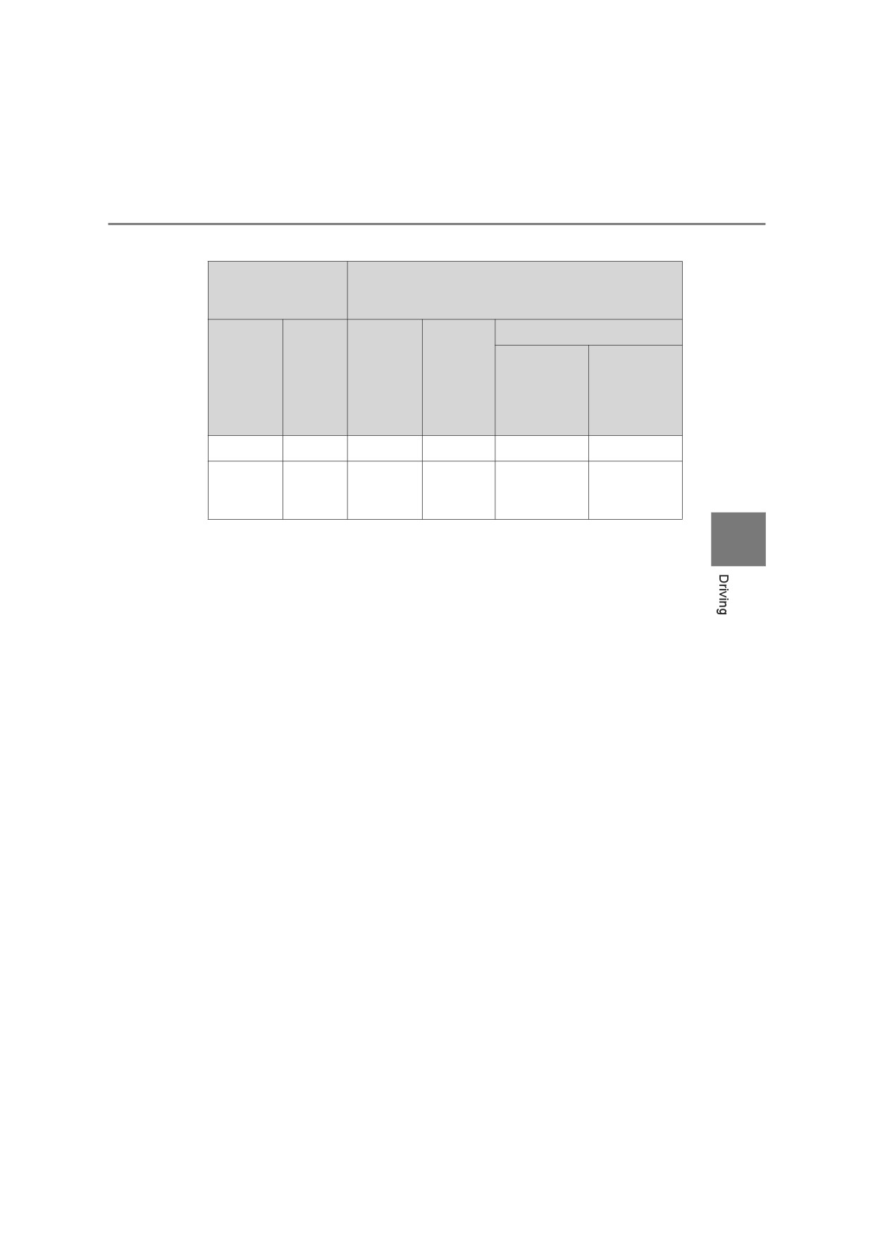
Q Guide to dial settings
Occupancy and
luggage load
Dial position
conditions
Double-cab models
Except for
For Russia,
Luggage
Single-cab
Smart-cab
Occupants
Russia,
load
models
models
Byelarus,
Byelarus,
Kazakhstan
Kazakhstan
and Armenia
and Armenia
Driver
None
0
0
0
0
Full
1
2.5*1
2*
2.5*3
Driver
luggage
3*2, 6
2.5
2.5*2
3*4
loading
3.5*2, 7
*1: Halogen headlights type A (P. 525)
4
*2: Halogen headlights type B (P. 525)
*3: Vehicles with Heavy Duty Suspension*5
*4: Vehicles without Heavy Duty Suspension*5
*5: Contact any authorized Toyota retailer or Toyota authorized repairer, or any
reliable repairer, if you are not sure of which specifications your vehicle is
equipped with.
*6: Except for GUN135L-DTTSXW models*8 without Heavy Duty Suspen-
sion*5
*7: For GUN135L-DTTSXW models*8 without Heavy Duty Suspension*5
*8: The model code is indicated on the manufacturer’ plate or label. (P. 624)
252
4-3. Operating the lights and wipers
Extended Headlight Lighting system (if equipped)
This system allows the headlights and front position lights to be turned
on for 30 seconds when the engine switch is turned to the “LOCK”
position (vehicles without smart entry & start system) or off (vehicles
with smart entry & start system).
Pull the lever toward you and
release it with the light switch is in
or
after turning the
engine switch to the “LOCK” posi-
tion (vehicles without smart entry
& start system) or off
(vehicles
with smart entry & start system).
Pull the lever toward you and
release it again to turn off the
lights.
Q Daytime running light system (if equipped)
To make your vehicle more visible to other drivers during daytime driving, the
daytime running lights turn on automatically whenever the engine is started
and the parking brake is released with the headlight switch in
. (Illuminate
brighter than the front position lights.) The daytime running light system is not
designed for use at night.
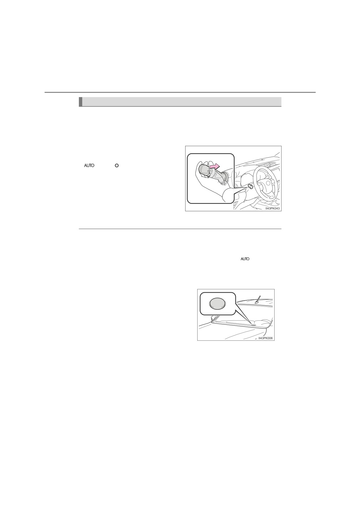
Q Headlight control sensor (if equipped)
The sensor may not function properly if an
object is placed on the sensor, or anything
that blocks the sensor is affixed to the
windshield.
Doing so interferes with the sensor
detecting the level of ambient light and
may cause the automatic headlight sys-
tem to malfunction.
4-3. Operating the lights and wipers
253
Q Automatic light off system (if equipped)
Models for model code destination Blank* (except for Kazakhstan)
The lights turn off after the engine switch is turned to the “LOCK” position
(vehicles without smart entry & start system) or off (vehicles with smart entry
& start system) and the driver’s door is opened.
To turn the lights on again, turn the engine switch to the “ON” position (vehi-
cles without smart entry & start system) or to IGNITION ON mode (vehicles
with smart entry & start system), or turn the light switch to
or
once
and then back to
or
Models for model code destination W*, and Kazakhstan
When the light switch is in
or
:
The headlights and front fog lights turn off after the engine switch is turned to
the “LOCK” position (vehicles without smart entry & start system) or off (vehi-
cles with smart entry & start system).
When the light switch is in AUTO:
The lights turn off after the engine switch is turned to the “LOCK” position
4
(vehicles without smart entry & start system) or off (vehicles with smart entry
& start system).
To turn the lights on again, turn the engine switch to the “ON” position (vehi-
cles without smart entry & start system) or to IGNITION ON mode (vehicles
with smart entry & start system), or turn the light switch to
or
once
and then back to
or
*: See “Checking your vehicle’s model” if you are not sure of which model
your vehicle is. (P. 12)
Q Light reminder buzzer (if equipped)
Vehicles without smart entry & start system
A buzzer sounds when the engine switch is turned to the “LOCK” position, the
key is removed and the driver’s door is opened while the lights are turned on.
Vehicles with smart entry & start system
A buzzer sounds when the engine switch is turned off and the driver’s door is
opened while the lights are turned on.
254
4-3. Operating the lights and wipers
Q Battery-saving function
Models for model code destination Blank* (except for Kazakhstan)
In order to prevent the battery of the vehicle from discharging, if the head-
lights and/or tail lights are on when the engine switch is turned to the “LOCK”
position (vehicles without smart entry & start system) or off (vehicles with
smart entry & start system), the battery-saving function will operate and auto-
matically turn off all the lights after approximately 20 minutes.
Models for model code destination W*, and Kazakhstan
In order to prevent the battery of the vehicle from discharging, if the light
switch is in
or
position when the engine switch is turned to the
“LOCK” position (vehicles without smart entry & start system) or off (vehicles
with smart entry & start system), the battery-saving function will operate and
automatically turn off all the lights after approximately 20 minutes.
When any of the following are performed, the battery-saving function is can-
celed once and then reactivated. All the lights will turn off automatically 20
minutes after the battery-saving function has been reactivated:
O When the headlight switch is operated
O When a door is closed once and then opened
*: See “Checking your vehicle’s model” if you are not sure of which model
your vehicle is. (P. 12)
Q Automatic headlight leveling system (if equipped)
The level of the headlights is automatically adjusted according to the number
of passengers and the loading condition of the vehicle to ensure that the
headlights do not interfere with other road users.
Q Customization
Settings (e.g. light sensor sensitivity) can be changed.
(Customizable features: P. 646)
NOTICE
Q To prevent battery discharge
Do not leave the lights on longer than necessary when the engine is not
running.
4-3. Operating the lights and wipers
255
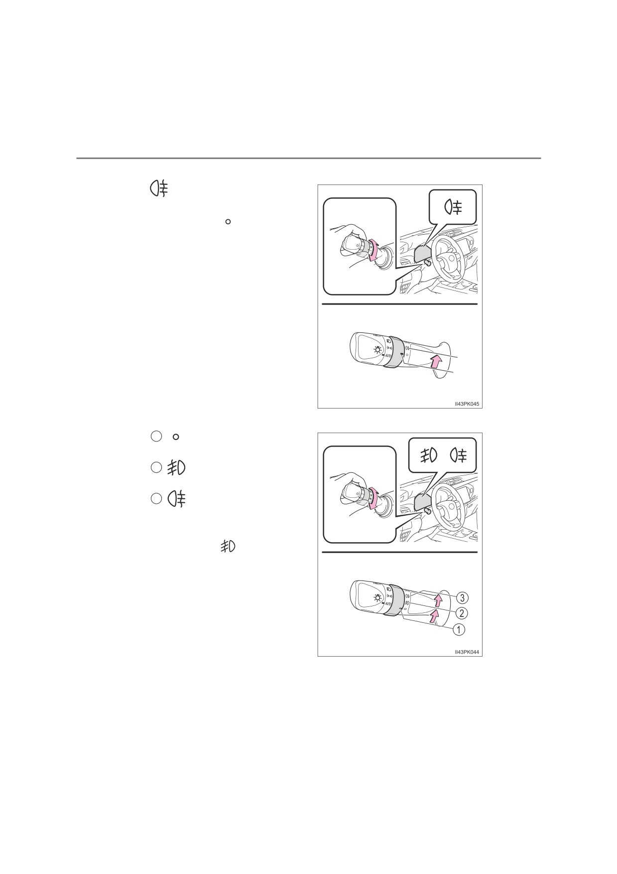
Fog light switch
The fog lights secure excellent visibility in difficult driving con-
ditions, such as in rain and fog.
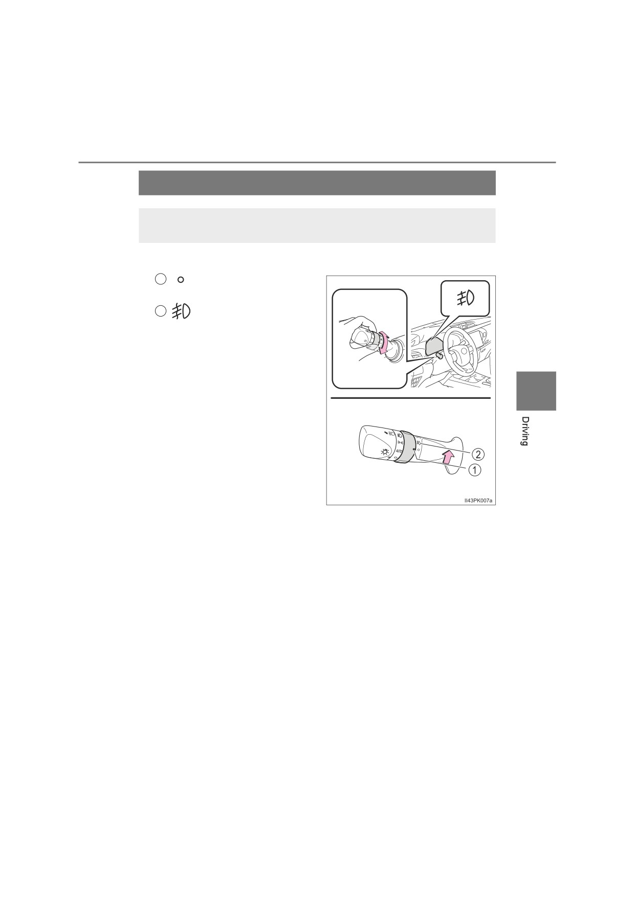
Q Front fog light switch (if equipped)
1
Turns the front fog lights
off
2
Turns the front fog lights
on
4
: If equipped
256
4-3. Operating the lights and wipers
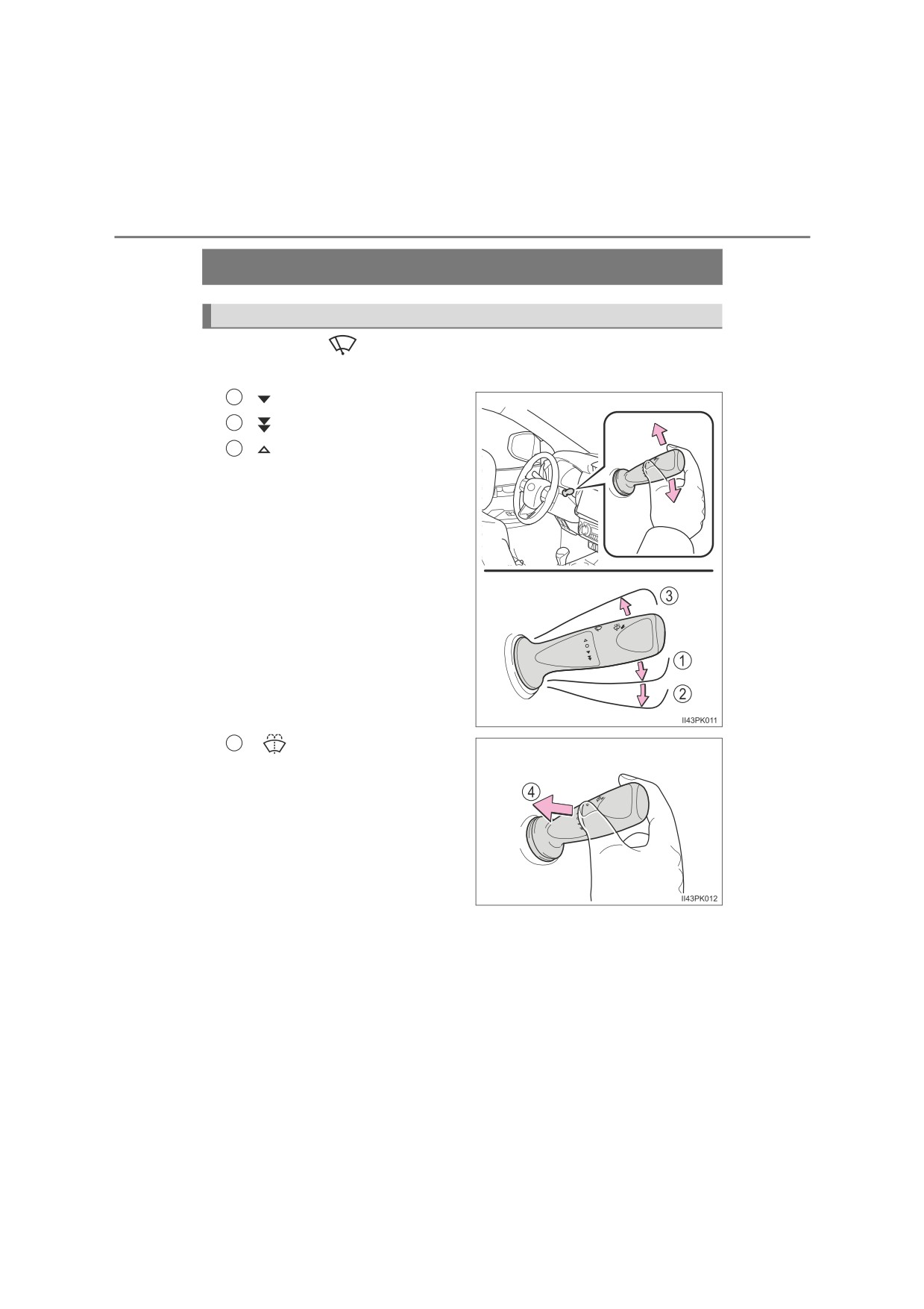
Q Rear fog light switch (if equipped)
Turns the rear fog light on
Releasing the switch ring
returns it to
Operating the switch ring again
turns the rear fog light off.
Q Front and rear fog light switch (if equipped)
1
Turns the front and rear
fog lights off
2
Turns the front fog lights
on
3
Turns both front and
rear fog lights on
Releasing the switch ring
returns it to
Operating the switch ring again
turns only the rear fog light off.
4-3. Operating the lights and wipers
257
Q Fog lights can be used when
Vehicles with front and rear fog lights
Front fog lights: The headlights or front position lights are turned on.
Rear fog light: The front fog lights are turned on.
Vehicles with rear fog light only
The headlights are turned on.
4
258
4-3. Operating the lights and wipers
Windshield wipers and washer
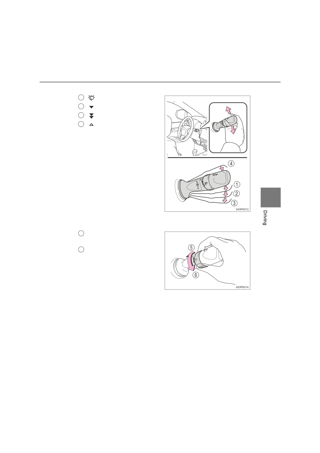
Operating the wiper lever
Operating the
lever operates the wipers or washer as follows.
Q Windshield wipers without intermittent operation
1
Low speed operation
2
High speed operation
3
Temporary operation
4
Washer operation
Pulling the lever operates the
washer.
4-3. Operating the lights and wipers
259
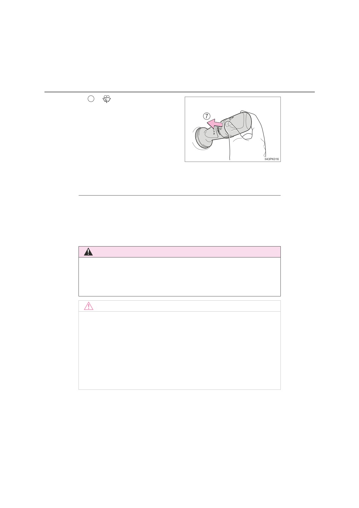
Q Windshield wipers with intermittent operation
1
Intermittent operation
2
Low speed operation
3
High speed operation
4
Temporary operation
4
If equipped, wiper intervals can be adjusted when intermittent oper-
ation is selected.
Increases the intermittent
5
windshield wiper frequency
Decreases the intermittent
6
windshield wiper frequency
260
4-3. Operating the lights and wipers
7
Washer/wiper dual
operation
Pulling the lever operates the
wipers and washer.
The wipers will automatically
operate a couple of times after
the washer squirts.
If the headlights are on, the
headlight cleaners will operate
once.
And then, the headlight cleaners
will operate every five times you
pull the lever. (if equipped)
Q The windshield wipers and washer can be operated when
The engine switch is in the “ON” position (vehicles without smart entry & start
system) or IGNITION ON mode (vehicles with smart entry & start system).
Q If no windshield washer fluid sprays
Check that the washer nozzles are not blocked if there is washer fluid in the
windshield washer fluid reservoir.
WARNING
Q Caution regarding the use of washer fluid
When it is cold, do not use the washer fluid until the windshield becomes
warm. The fluid may freeze on the windshield and cause low visibility. This
may lead to an accident, resulting in death or serious injury.
NOTICE
Q When the windshield is dry
Do not use the wipers, as they may damage the windshield.
Q When the washer fluid tank is empty
Do not operate the switch continually as the washer fluid pump may over-
heat.
Q When a nozzle becomes blocked
In this case, contact any authorized Toyota retailer or Toyota authorized
repairer, or any reliable repairer.
Do not try to clear it with a pin or other object. The nozzle will be damaged.

4-4. Refueling
261
Opening the fuel tank cap
Perform the following steps to open the fuel tank cap:
Before refueling the vehicle
O Close all the doors and windows, and turn the engine switch to the
“LOCK” position (vehicles without smart entry & start system) or off
(vehicles with smart entry & start system).
O Confirm the type of fuel.
Q Fuel types
P. 643
Q Fuel tank opening for unleaded gasoline (gasoline engine)
To help prevent incorrect fueling, your vehicle has a fuel tank opening that
4
only accommodates the special nozzle on unleaded fuel pumps.

262
4-4. Refueling
WARNING
Q When refueling the vehicle
Observe the following precautions while refueling the vehicle. Failure to do
so may result in death or serious injury.
OAfter exiting the vehicle and before opening the fuel cap, touch an
unpainted metal surface to discharge any static electricity. It is important to
discharge static electricity before refueling because sparks resulting from
static electricity can cause fuel vapors to ignite while refueling.
O Type A (P. 263) only: Always hold the grips on the fuel tank cap and turn
it slowly to remove it.
A whooshing sound may be heard when the fuel tank cap is loosened.
Wait until the sound cannot be heard before fully removing the cap. In hot
weather, pressurized fuel may spray out the filler neck and cause injury.
ODo not allow anyone that has not discharged static electricity from their
body to come close to an open fuel tank.
ODo not inhale vaporized fuel.
Fuel contains substances that are harmful if inhaled.
ODo not smoke while refueling the vehicle.
Doing so may cause the fuel to ignite and cause a fire.
ODo not return to the vehicle or touch any person or object that is statically
charged.
This may cause static electricity to build up, resulting in a possible ignition
hazard.
Q When refueling
Observe the following precautions to prevent fuel overflowing from the fuel
tank:
OSecurely insert the fuel nozzle into the fuel filler neck.
O Stop filling the tank after the fuel nozzle automatically clicks off.
ODo not top off the fuel tank.
4-4. Refueling
263
NOTICE
Q Refueling
ODo not spill fuel during refueling.
Doing so may damage the vehicle, such as causing the emission control
system to operate abnormally or damaging fuel system components or the
vehicle’s painted surface.
O Vehicles with DPF system:
Use the specified fuel. If fuel other than the specified fuel is used, white
smoke may be continuously emitted from the exhaust pipe during regener-
ating the filter. (P. 369)
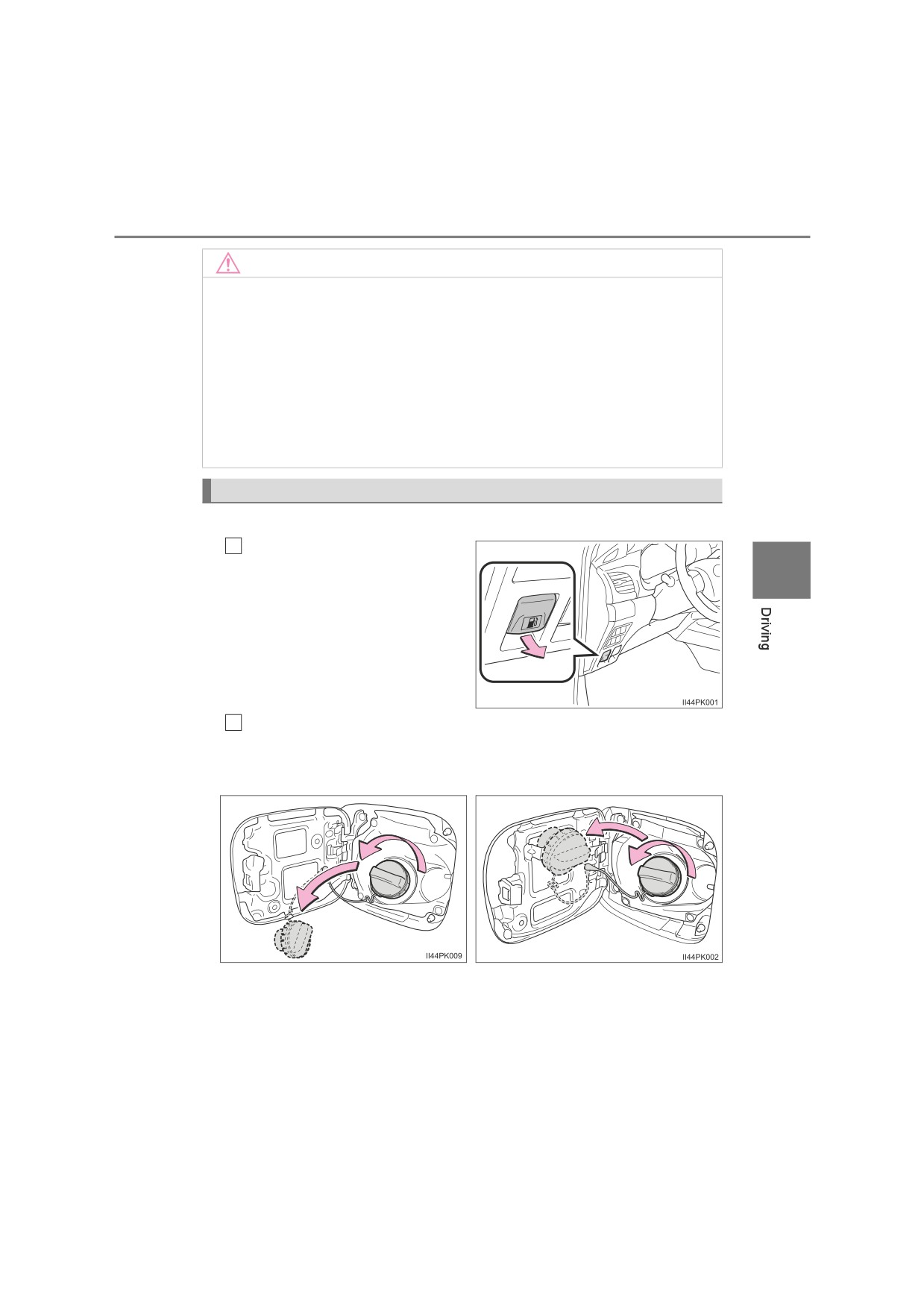
Opening the fuel tank cap
Q Type A
1
Pull up the opener to open
the fuel filler door.
4
2
Turn the fuel tank cap slowly to remove it and hang it on the back
of the fuel filler door.
Without over fender
With over fender
264
4-4. Refueling
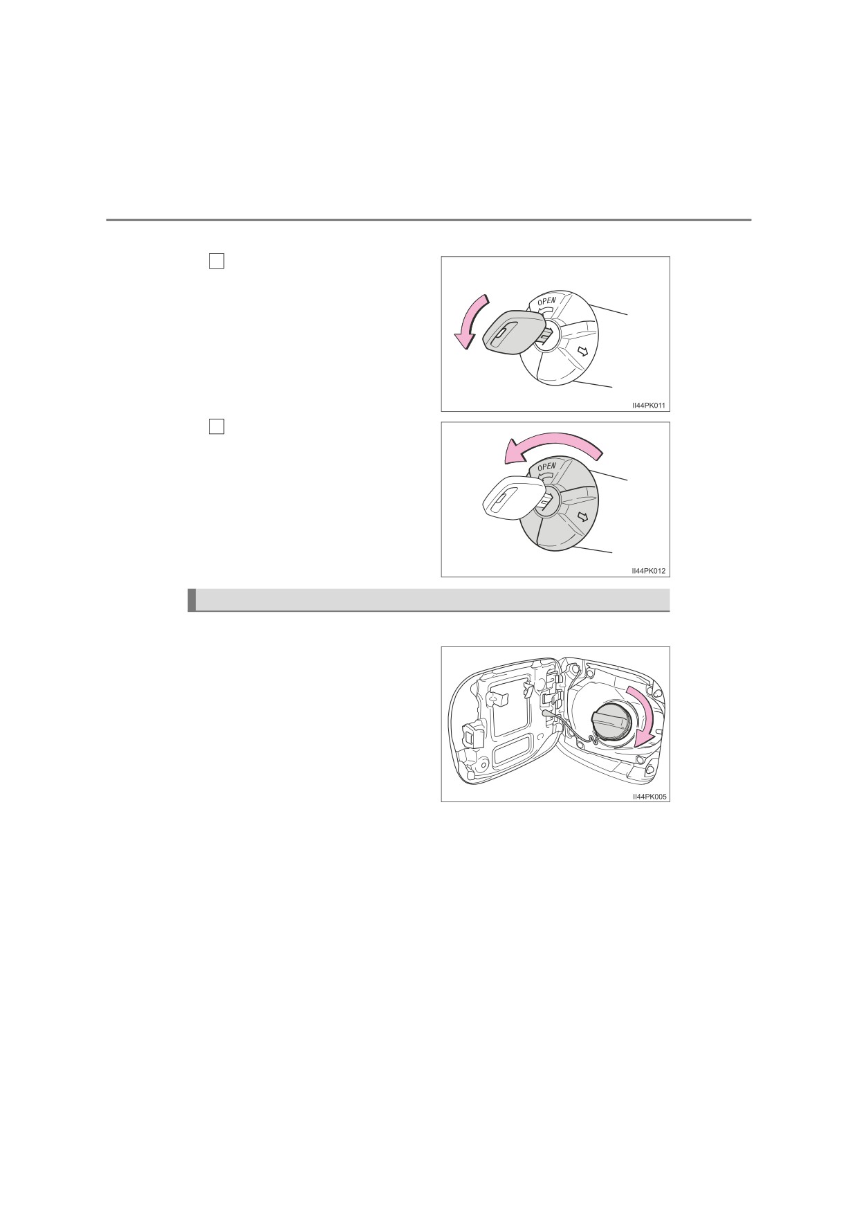
Q Type B
To unlock the fuel tank cap,
1
insert the key and turn it
counterclockwise.
2
Turn the fuel tank cap slowly
to open.
Make sure not to hold and turn
the key.
Closing the fuel tank cap
Q Type A
After refueling, turn the fuel
tank cap until you hear a click.
Once the cap is released, it will
turn slightly in the opposite
direction.
4-4. Refueling
265
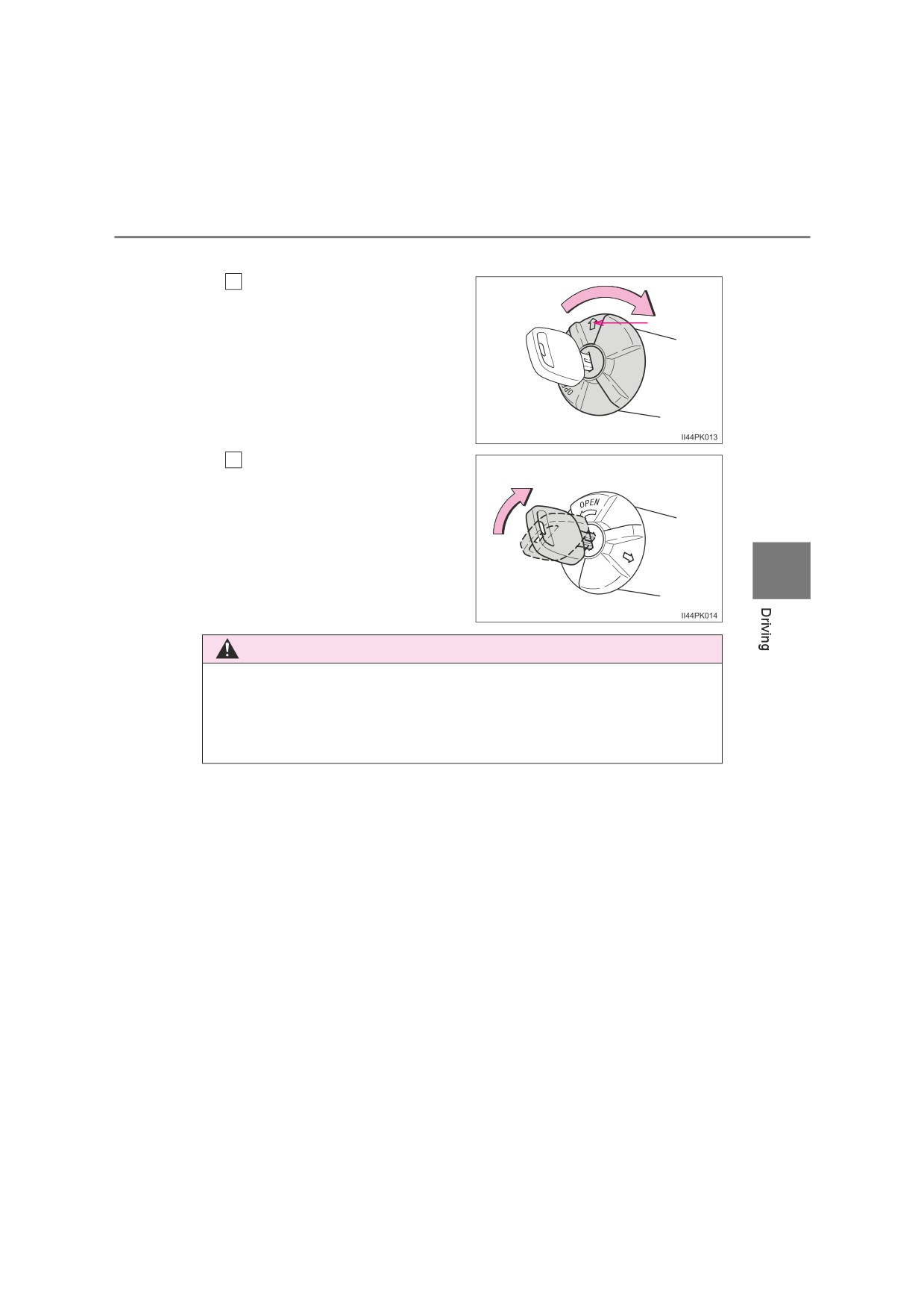
Q Type B
Close the fuel tank cap
1
Make sure to put the fuel tank
cap with the arrow upward and
Arrow
turn it slowly to close.
When turning the fuel tank cap,
do not hold and turn the key.
Lock the fuel cap
2
Turning the fuel cap key clock-
wise.
4
WARNING
Q When replacing the fuel tank cap
Do not use anything but a genuine Toyota fuel tank cap designed for your
vehicle. Doing so may cause a fire or other incident which may result in
death or serious injury.

266
4-5. Using the driving support systems
Toyota Safety Sense
The Toyota Safety Sense consists of the following drive assist
systems and contributes to a safe and comfortable driving expe-
rience:
Driving assist system
X PCS (Pre-Collision System)
P. 273
X LDA (Lane Departure Alert With Yaw Assist Function)
P. 284
X RSA (Road Sign Assist)
P. 295
X Dynamic radar cruise control
P. 301
WARNING
Q Toyota Safety Sense
The Toyota Safety Sense is designed to operate under the assumption that
the driver will drive safely, and is designed to help reduce the impact to the
occupants and the vehicle in the case of a collision or assist the driver in
normal driving conditions.
As there is a limit to the degree of recognition accuracy and control perfor-
mance that this system can provide, do not overly rely on this system. The
driver is always responsible for paying attention to the vehicle’s surround-
ings and driving safely.
: If equipped
4-5. Using the driving support systems
267
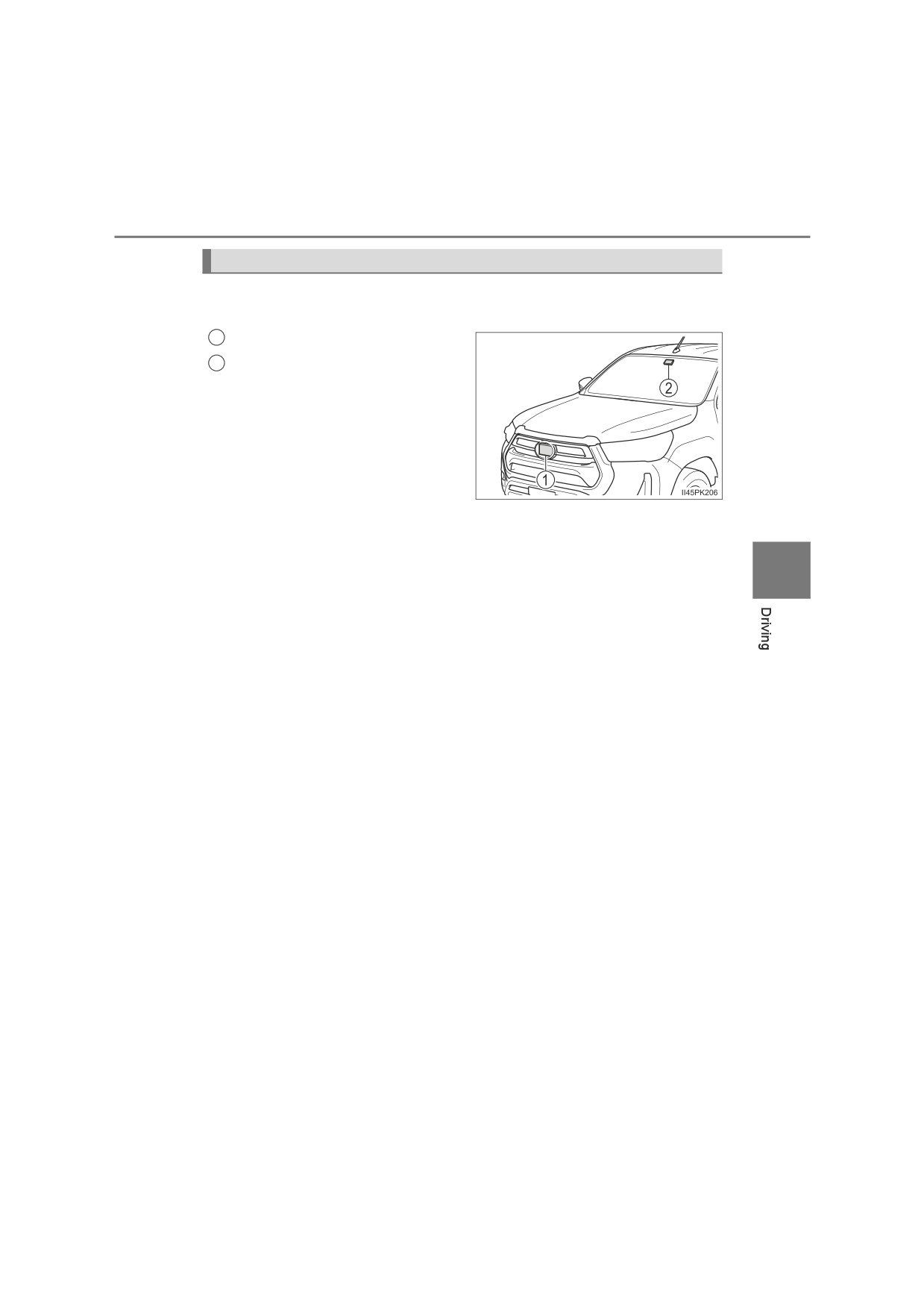
Sensors
Two types of sensors, located behind the front grille and windshield,
detect information necessary to operate the drive assist systems.
1
Radar sensor
2
Front camera
4
268
4-5. Using the driving support systems
WARNING
Q To avoid malfunction of the radar sensor
Observe the following precautions.
Otherwise, the radar sensor may not operate properly, possibly leading to
an accident resulting in death or serious injury.
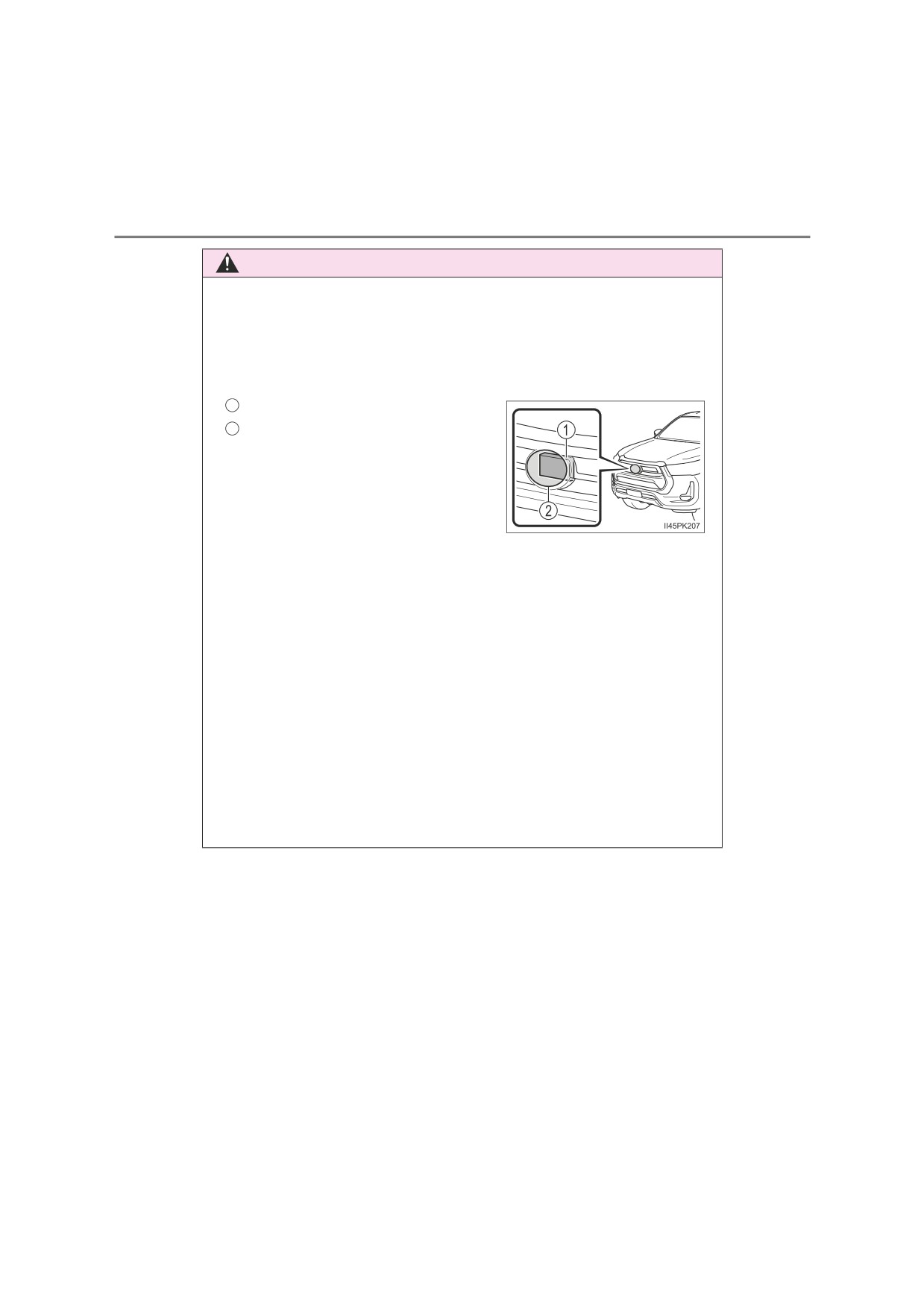
O Keep the radar sensor and the radar sensor cover clean at all times.
1
Radar sensor
2
Radar sensor cover
If the front of the radar sensor or the
front or back of the radar sensor cover
is dirty or covered with water droplets,
snow, etc., clean it.
Clean the radar sensor and radar
sen-
sor cover with a soft cloth to avoid
damaging them.
ODo not attach accessories, stickers (including transparent stickers) or
other items to the radar sensor, radar sensor cover or surrounding area.
ODo not subject the radar sensor or its surrounding area to a strong impact.
If the radar sensor, front grille, or front bumper has been subjected to a
strong impact, have the vehicle inspected by any authorized Toyota
retailer or Toyota authorized repairer, or any reliable repairer.
ODo not disassemble the radar sensor.
ODo not modify or paint the radar sensor or radar sensor cover.
O In the following cases, the radar sensor must be recalibrated. Contact any
authorized Toyota retailer or Toyota authorized repairer, or any reliable
repairer for details.
• When the radar sensor or front grille are removed and installed, or
replaced
• When the front bumper is replaced
4-5. Using the driving support systems
269
WARNING
Q To avoid malfunction of the front camera
Observe the following precautions.
Otherwise, the front camera may not operate properly, possibly leading to
an accident resulting in death or serious injury.
OKeep the windshield clean at all times.
• If the windshield is dirty or covered with an oily film, water droplets,
snow, etc., clean the windshield.
• If a glass coating agent is applied to the windshield, it will still be neces-
sary to use the windshield wipers to remove water droplets, etc. from
the area of the windshield in front of the front camera.
• If the inner side of the windshield where the front camera is installed is
dirty, contact any authorized Toyota retailer or Toyota authorized
repairer, or any reliable repairer.
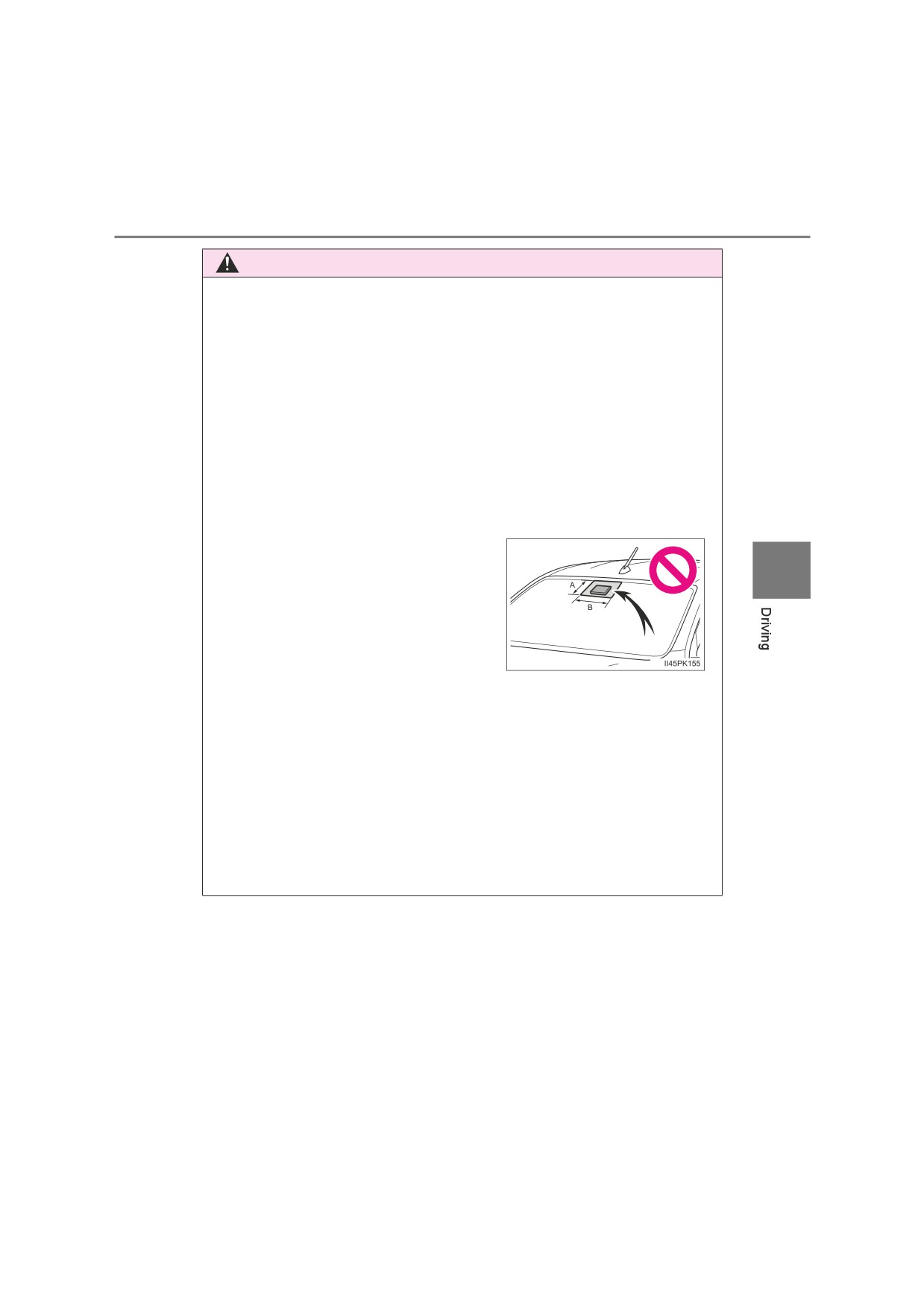
ODo not attach objects, such as stickers,
transparent stickers, etc., to the outer
4
side of the windshield in front of the
front camera (shaded area in the illus-
tration).
A: From the top of the windshield to
approximately 1 cm (0.4 in.) below the
bottom of the front camera
B: Approximately
20 cm
(7.9 in.)
(Approximately 10 cm [4.0 in.] to the
right and left from the center of the
front camera)
O If the part of the windshield in front of the front camera is fogged up or cov-
ered with condensation, or ice, use the windshield defogger to remove
the
fog, condensation, or ice. (P. 435, 443)
O If water droplets cannot be properly removed from the area of the wind-
shield in front of the front camera by the windshield wipers, replace the
wiper insert or wiper blade.
ODo not attach window tint to the windshield.
270
4-5. Using the driving support systems
WARNING
OReplace the windshield if it is damaged or cracked.
After replacing the windshield, the front camera must be recalibrated. Con-
tact any authorized Toyota retailer or Toyota authorized repairer, or any
reliable repairer for details.
ODo not allow liquids to contact the front camera.
ODo not allow bright lights to shine into the front camera.
ODo not dirty or damage the front camera.
When cleaning the inside of the windshield, do not allow glass cleaner to
contact the lens of the front camera. Also, do not touch the lens.
If the lens is dirty or damaged, contact any authorized Toyota retailer or
Toyota authorized repairer, or any reliable repairer.
ODo not subject the front camera to a strong impact.
ODo not change the installation position or direction of the front camera or
remove it.
ODo not disassemble the front camera.
ODo not modify any components of the vehicle around the front camera
(inside rear view mirror, etc.) or ceiling.
ODo not attach any accessories to the hood, front grille or front bumper that
may obstruct the front camera. Contact any authorized Toyota retailer or
Toyota authorized repairer, or any reliable repairer for details.
O If a surfboard or other long object is to be mounted on the roof, make sure
that it will not obstruct the front camera.
ODo not modify the headlights or other lights.

4-5. Using the driving support systems
271
Q If a warning message is displayed on the multi-information display
A system may be temporarily unavailable or there may be a malfunction in
the system.
O In the following situations, perform the actions specified in the table. When
the normal operating conditions are detected, the message will disappear
and the system will become operational.
If the message does not disappear, contact any authorized Toyota retailer
or Toyota authorized repairer, or any reliable repairer.
Situation
Actions
When the area around a cam-
era is covered with dirt, mois-
Using the wiper and A/C function,
ture
(fogged up, covered with
remove the dirt and other attached mat-
condensation, ice, etc.), or
ter. (P. 435, 443)
other foreign matter
If the front camera is hot, such as after
4
the vehicle had been parked in the sun,
use the air conditioning system to
decrease the temperature around the
front camera.
If a sunshade was used when the vehi-
When the temperature around
cle was parked, depending on its type,
the front camera is outside of
the sunlight reflected from the surface
the operational range, such as
of the sunshade may cause the tem-
when the vehicle is in the sun or
perature of the front camera to become
in an extremely cold environ-
excessively high.
ment
If the front camera is cold, such after the
vehicle is parked in an extremely cold
environment, use the air conditioning
system to increase the temperature
around the front camera.
The area in front of the front
camera is obstructed, such as
when the hood is open or a
Close the hood, remove the sticker, etc.
sticker is attached to the part of
to clear the obstruction.
the windshield in front of the
front camera.
Check whether there is attached materi-
When
“Pre-Collision System
als on the radar sensor and radar sensor
Unavailable” is displayed.
cover, and if there is, remove it.
272
4-5. Using the driving support systems
OIn the following situations, if the situation has changed (or the vehicle has
been driven for some time) and the normal operating conditions are
detected, the message will disappear and the system will become opera-
tional.
If the message does not disappear, contact any authorized Toyota retailer
or Toyota authorized repairer, or any reliable repairer.
• When the temperature around the radar sensor is outside of the opera-
tional range, such as when the vehicle is in the sun or in an extremely
cold environment
• When the front camera cannot detect objects in front of the vehicle, such
as when driving in the dark, snow, or fog, or when bright lights are shining
into the front camera
• Depending on the conditions in the vicinity of the vehicle, the radar may
judge the surrounding environment can not be properly recognized. In
that case, “Pre-Collision System Unavailable” is displayed.