Toyota Venza Hybrid (2021 year). Manual in english - part 2
 

  Index      Toyota     Toyota Venza Hybrid (2021 year). Manual in english


Search            copyright infringement  


Content      ..      1      2      3      ..


Toyota Venza Hybrid (2021 year). Manual in english - part 2


77

1-5. Theft deterrent system

1

For
 safety and secu

rity

1-5.Theft deterrent system

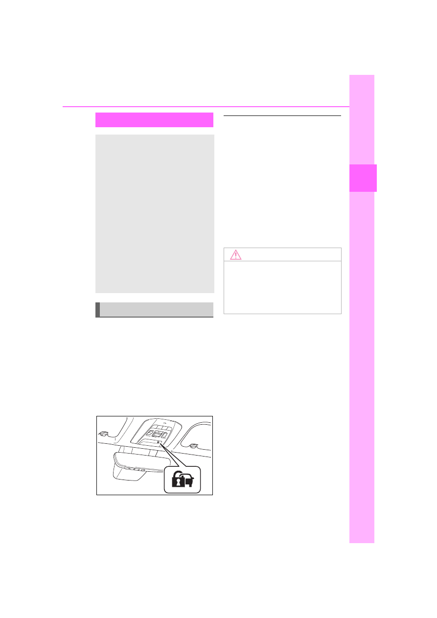
The indicator light flashes after 
the power switch has been 
turned to OFF to indicate that 
the system is operating.
The indicator light stops flashing 
after the power switch has been 
turned to ACC or ON to indicate 
that the system has been can-
celed.

System maintenance

The vehicle has a maintenance-free 

type immobilizer system.

Conditions that may cause the 

system to malfunction

If the grip portion of the key is in 

contact with a metallic object

If the key is in close proximity to or 

touching a key to the security sys-

tem (key with a built-in transpon-

der chip) of another vehicle

Certification for the immobi-

lizer system

P.152

Immobilizer system

The vehicle’s keys have 
built-in transponder chips 
that prevent the hybrid sys-
tem from starting if a key 
has not been previously 
registered in the vehicle’s 
on-board computer.
Never leave the keys inside 
the vehicle when you leave 
the vehicle.

This system is designed to 
help prevent vehicle theft but 
does not guarantee absolute 
security against all vehicle 
thefts.

Operating the system

NOTICE

To ensure the system oper-

ates correctly

Do not modify or remove the sys-

tem. If modified or removed, the 

proper operation of the system 

cannot be guaranteed.

-------------------------------------------------------------------------------------------------------------------------------------------------------------

78

1-5. Theft deterrent system

*

: If equipped

Items to check before lock-
ing the vehicle

To prevent unexpected trigger-
ing of the alarm and vehicle 
theft, make sure of the following:

Nobody is in the vehicle.

The side windows are closed 
before the alarm is set.

No valuables or other per-
sonal items are left in the 
vehicle.

Setting

Close the doors, hood, and lock 
all the doors. The system will be 
set automatically after 30 sec-
onds.

The security indicator changes 
from being on to flashing when 
the system is set.
If all doors are closed with hood 
open, alarm system can be set.

Canceling or stopping

Do one of the following to deac-
tivate or stop the alarm:

Unlock the doors.

Turn the power switch to ACC 
or ON, or start the hybrid sys-
tem. (The alarm will be deacti-
vated or stopped after a few 
seconds.)

System maintenance

The vehicle has a maintenance-free 

type alarm system.

Triggering of the alarm

The alarm may be triggered in the 

following situations:

(Stopping the alarm deactivates the 

alarm system.)
The doors are unlocked using the 

mechanical key.

Alarm

*

The alarm uses light and 
sound to give an alert when 
an intrusion is detected.
The alarm is triggered in the 
following situations when 
the alarm is set:

A locked door is unlocked or 
opened in any way other 
than using the entry func-
tion or wireless remote con-
trol. (The doors will lock 
again automatically.)

The hood is opened.

Setting/canceling/stop-
ping the alarm system

-------------------------------------------------------------------------------------------------------------------------------------------------------------

79

1-5. Theft deterrent system

1

For
 safety and secu

rity

If a door is unlocked using the 

mechanical key while the alarm is 

set, a warning will sound intermit-

tently for approximately 10 sec-

onds.If the alarm is not canceled or 

stopped during this time, the warn-

ing pattern changes and the warn-

ing sounds for a certain period of 

time.

A person inside the vehicle opens 

a door or hood, or unlocks the 

vehicle using an inside lock but-

ton.

The 12-volt battery is recharged or 

replaced when the vehicle is 

locked. (

P.469)

Alarm-operated door lock

In the following cases, depending 

on the situation, the door may auto-

matically lock to prevent improper 

entry into the vehicle:

When a person remaining in the 

vehicle unlocks the door and the 

alarm is activated.

While the alarm is activated, a 

person remaining in the vehicle 

unlocks the door.

When recharging or replacing the 

12-volt battery.

NOTICE

To ensure the system oper-

ates correctly

Do not modify or remove the sys-

tem. If modified or removed, the 

proper operation of the system 

cannot be guaranteed.

-------------------------------------------------------------------------------------------------------------------------------------------------------------

80

1-5. Theft deterrent system

These labels are attached to the 
vehicle to reduce vehicle theft 
by facilitating the tracing and 
recovery of parts from stolen 
vehicles.
Do not remove under penalty of 
law.

Theft prevention 

labels (U.S.A.)

-------------------------------------------------------------------------------------------------------------------------------------------------------------

81

2

2

Vehicle

 statu

s information an

d in
dicator

s

Vehicle status informa-

tion and indicators

2-1. Instrument cluster

Warning lights and indica-

tors ...............................

82

Gauges and meters (Vehi-

cles with 4.2-inch display)

.....................................

87

Gauges and meters (Vehi-

cles with 7-inch display)

91

Multi-information display 

(4.2-inch display)..........

94

Multi-information display (7-

inch display) ..............

105

Head-up display ..........

116

Energy monitor/consump-

tion screen.................

120

-------------------------------------------------------------------------------------------------------------------------------------------------------------

82

2-1. Instrument cluster

2-1.Instrument cluster

For the purpose of explanation, the following illustrations display all 
warning lights and indicators illuminated.

Vehicles with 4.2-inch display

The units used on the meters and some indicators may differ depending on 
the target region.

Vehicles with 7-inch display

Warning lights and indicators

The warning lights and indicators on the instrument cluster, 
overhead console panel and outside rear view mirrors inform 
the driver of the status of the vehicle’s various systems.

Instrument cluster

-------------------------------------------------------------------------------------------------------------------------------------------------------------

83

2-1. Instrument cluster

2

Vehicle

 statu

s information an

d in
dicator

s

The units used on the meters and some indicators may differ depending on 
the target region.

Warning lights inform the driver 
of malfunctions in the indicated 
vehicle’s systems.

Warning lights

(U.S.A.)

Brake system warn-
ing light

*1

 (

P.442)

(Canada)

(Red)

Brake system warn-
ing light

*1

 (

P.442)

(Yellow)

Brake system warn-
ing light

*1

 (

P.442)

Charging system 
warning light

*2


(

P.442)

High coolant tempera-
ture warning light

*2


(

P.443)

Low engine oil pres-
sure warning light

*2


(

P.443)

(U.S.A.)

Malfunction indicator 
lamp

*1

 (

P.443)

(Canada)

Malfunction indicator 
lamp

*1

 (

P.443)

SRS warning light

*1


(

P.443)

(U.S.A.)

ABS warning light

*1


(

P.444)

(Canada)

ABS warning light

*1


(

P.444)

(Red/yellow)

Electric power steer-
ing system warning 
light

*1

 (

P.444)

(Flashes or 

illuminates)

PCS warning light

*1


(

P.444)

(Orange)

LTA indicator 
(

P.445)

Intuitive parking assist 
OFF indicator

*3

 (if 

equipped) (

P.445)

PKSB OFF indica-
tor

*1

 (if equipped) 

(

P.445)

RCTA OFF indica-
tor

*1

 (

P.446)

Slip indicator light

*1


(

P.446)

Brake Override Sys-
tem/Drive-Start Con-
trol/PKSB (if 
equipped) warning 
light

*2

 (

P.447)

(Flashes)

Brake hold operated 
indicator

*1

 (

P.447)

(U.S.A.)

(Flashes)

Parking brake indica-
tor (

P.448)

-------------------------------------------------------------------------------------------------------------------------------------------------------------

84

2-1. Instrument cluster

*1

:These lights turn on when the 

power switch is turned to ON to 
indicate that a system check is 
being performed. They will turn 
off after the hybrid system is on, 
or after a few seconds. There 
may be a malfunction in a sys-
tem if the light does not come on, 
or turn off. Have the vehicle 
inspected by your Toyota dealer.

*2

:This light illuminates on the 

multi-information display with a 
message.

*3

:Intuitive parking assist OFF indi-

cator turns on when the power 
switch is turned to ON while the 
Intuitive parking assist function is 
on. It will turn off after a few sec-
onds.

(Canada)
(Flashes)

Parking brake indica-
tor (

P.448)

Tire pressure warning 
light

*1

 (

P.448)

Low fuel level warn-
ing light (

P.448)

Driver’s and front pas-
senger’s seat belt 
reminder light 
(

P.449)

Rear passengers’ seat 
belt reminder light 
(

P.449)

WARNING

If a safety system warning 

light does not come on

Should a safety system light such 

as the ABS and SRS warning light 

not come on when you start the 

hybrid system, this could mean 

that these systems are not avail-

able to help protect you in an acci-

dent, which could result in death 

or serious injury. Have the vehicle 

inspected by your Toyota dealer 

immediately if this occurs.

-------------------------------------------------------------------------------------------------------------------------------------------------------------

85

2-1. Instrument cluster

2

Vehicle

 statu

s information an

d in
dicator

s

The indicators inform the driver 
of the operating state of the 
vehicle’s various systems.

Indicators

Turn signal indicator 
(

P.207)

(U.S.A.)

Headlight indicator 
(

P.214)

(Canada)

Tail light indicator 
(

P.214)

Headlight high beam 
indicator (

P.216)

Automatic High Beam 
indicator (

P.217)

Smart key system 
indicator

*1, 2

 (

P.196)

Smart key system 
indicator

*1, 3

 (

P.196)

Cruise control indica-
tor (

P.256)

Dynamic radar cruise 
control indicator 
(

P.256)

Cruise control “SET” 
indicator (

P.256)

LTA indicator

*4


(

P.248)

Intuitive parking assist 
OFF indicator

*5, 6

 (if 

equipped) (

P.277)

PKSB OFF indicator

*5, 

7

 (if equipped) 

(

P.284)

(Flashes)

Slip indicator light

*7


(

P.299)

VSC OFF indicator

*5, 

7

 (

P.300)

PCS warning light

*5, 7


(

P.235)

BSM outside rear view 
mirror indicators

*7, 8


(

P.267)

BSM OFF indicator 
(

P.267)

RCTA OFF indica-
tor

*5, 7

 (

P.267)

Brake hold standby 
indicator

*7

 (

P.211)

Brake hold operated 
indicator

*7

 (

P.211)

Security indicator

*9


(

P.77, 78)

“READY” indicator 
(

P.196)

Low outside tempera-
ture indicator

*10


(

P.89, 92)

EV indicator (

P.69)

(U.S.A.)

Parking brake indica-
tor (

P.208)

(Canada)

Parking brake indica-
tor (

P.208)

EV drive mode indica-
tor (

P.202)

Eco drive mode indi-
cator (

P.297)

-------------------------------------------------------------------------------------------------------------------------------------------------------------

86

2-1. Instrument cluster

*1

:This light illuminates on the 

multi-information display with a 
message.

*2

:Vehicles with 4.2-inch display

*3

:Vehicles with 7-inch display

*4

:Depending on the operating con-

ditions of the system, the color 
and state (illuminated/blinking) of 
the indicator change.

*5

:The light comes on when the 

system is turned off.

*6

:Intuitive parking assist OFF indi-

cator turns on when the power 
switch is turned to ON while the 
Intuitive parking assist function is 
on. It will turn off after a few sec-
onds.

*7

:These lights turn on when the 

power switch is turned to ON to 
indicate that a system check is 
being performed. They will turn 
off after the hybrid system is on, 
or after a few seconds. There 
may be a malfunction in a sys-
tem if the lights do not turn on, or 
turn off. Have the vehicle 
inspected by your Toyota dealer.

*8

:This light illuminates on the out-

side rear view mirrors.

*9

:This light illuminates on the over-

head console panel.

*10

: When the outside temperature 

is approximately 37°F (3°C) or 
lower, the indicator will flash for 
approximately 10 seconds, then 
stay on.

BSM (Blind Spot Monitor) out-

side rear view mirror indicators

In order to confirm operation, the 

BSM outside rear view mirror indica-

tors illuminate in the turning the 

BSM function/RCTA function on 

(

P.268).

If the system is functioning correctly, 

the BSM outside rear view mirror 

indicators will turn off after a few 

seconds.
If the BSM outside rear view mirror 

indicators do not illuminate or do not 

turn off, there may be a malfunction 

in the system. If this occurs, have 

the vehicle inspected by your 

Toyota dealer.

Sport mode indicator 
(

P.297)

“AIR BAG ON/OFF” 
indicator

*7, 9

 (

P.41)

-------------------------------------------------------------------------------------------------------------------------------------------------------------

87

2-1. Instrument cluster

2

Vehicle

 statu

s information an

d in
dicator

s

The units used on the meter and display may differ depending on the target 
region.

Hybrid System Indicator

Displays hybrid system output or regeneration level (

P.88)

Outside temperature (

P.89)

Clock

The GPS clock’s time is automatically adjusted by utilizing GPS time infor-
mation.
For details, refer to the “NAVIGATION AND MULTIMEDIA SYSTEM 
OWNER’S MANUAL”.

Multi-information display

Presents the driver with a variety of driving-related data (

P.94)

Displays warning messages if a malfunction occurs (

P.453)

Speedometer

Displays the vehicle speed

Fuel gauge

Displays the quantity of fuel remaining in the tank

Gauges and meters (Vehicles with 4.2-inch dis-

play)

The meters display various drive information.

Meter display

A

B

C

D

E

F

-------------------------------------------------------------------------------------------------------------------------------------------------------------

88

2-1. Instrument cluster

Odometer, trip meter and oil maintenance

Odometer:
Displays the total distance that the vehicle has been driven
Trip meter:
Displays the distance the vehicle has been driven since the meter was last 
reset. Trip meters “A” and “B” can be used to record and display different 
distances independently.
Oil maintenance:
Displays the distance until the next engine oil change.

Shift position and shift range indicator

Displays the selected shift position or selected shift range (

P.204)

Engine coolant temperature gauge

Displays the engine coolant temperature

The meters and display illumi-

nate when

The power switch is in ON.

Hybrid System Indicator

READY OFF area

Shows that the hybrid system is not 
operating.

Charge area

Shows regeneration

*

 status.

Regenerated energy will be used to 
charge the hybrid battery (traction 
battery).

Hybrid Eco area

Shows that gasoline engine power 
is not being used very often.
The gasoline engine will automati-
cally stop and restart under various 
conditions.

Eco area

Shows that the vehicle is being 
driven in an Eco-friendly manner.

G

H

I

A

B

C

D

-------------------------------------------------------------------------------------------------------------------------------------------------------------

89

2-1. Instrument cluster

2

Vehicle

 statu

s information an

d in
dicator

s

By keeping the indicator needle 
within Eco area, more Eco-friendly 
driving can be achieved.

Power area

Shows that an Eco-friendly driving 
range is being exceeded (during full 
power driving etc.)

*

: When used in this manual, “regen-

eration” refers to the conversion of 
energy created by the movement 
of the vehicle into electrical 
energy.

In the following situation, the Hybrid 

System Indicator does not operate.

“READY” indicator is not illumi-

nated.

The shift position is in a range 

other than D or S.

Outside temperature display

In the following situations, the cor-

rect outside temperature may not 

be displayed, or the display may 

take longer than normal to 

change.

• When stopped, or driving at low 

speeds (less than 12 mph [20 

km/h])

• When the outside temperature 

has changed suddenly (at the 

entrance/exit of a garage, tunnel, 

etc.)

When “--” or “E” is displayed, the 

system may be malfunctioning.

Take your vehicle to your Toyota 

dealer.

Displays the outside temperature 

within the range of -40°F (-40°C) 

to 122°F (50°C).

When the outside temperature is 

approximately 37°F (3°C) or 
lower, the indicator 

 will flash 

for approximately 10 seconds, 

then stay on.

Liquid crystal display

P.95

Switches the items of the odom-
eter, trip meter A, trip meter B 

and 

 (oil maintenance) by 

pressing the “ODO TRIP” 
switch.
When the trip meter is dis-
played, pressing and holding the 
switch will reset the trip meter.

E

WARNING

The information display at 

low temperatures

Allow the interior of the vehicle to 

warm up before using the liquid 

crystal information display. At 

extremely low temperatures, the 

display monitor may respond 

slowly, and display changes may 

be delayed.
For example, there is a lag 

between the driver’s shifting and 

the new shift range appearing on 

the display. This lag could cause 

the driver to downshift again, 

causing rapid and excessive 

engine braking and possibly an 

accident resulting in death or 

injury.

NOTICE

To prevent damage to the 

engine and its components

The engine may be overheating if 

the engine coolant temperature 

gauge is in the red zone (“H”). In 

this case, immediately stop the 

vehicle in a safe place, and check 

the engine after it has cooled 

completely. (

P.474)

Using the “ODO TRIP” 
switch

-------------------------------------------------------------------------------------------------------------------------------------------------------------

90

2-1. Instrument cluster

Pop-up display

Distance until the next engine oil 
change will be displayed when a 
warning message indicating that 
oil maintenance is required or 
should be performed soon is 
displayed.

The brightness of the instrument 
panel lights can be adjusted by 
turning the dial.

1

Brighter

2

Darker

Instrument cluster brightness 

adjustment

The instrument cluster brightness 

levels when the tail lights are on and 

off can be adjusted individually. 

However, when the surroundings 

are bright (daytime, etc.), turning on 

the tail lights will not change the 

instrument cluster brightness.

Instrument panel light 
control

-------------------------------------------------------------------------------------------------------------------------------------------------------------

91

2-1. Instrument cluster

2

Vehicle

 statu

s information an

d in
dicator

s

The units used on the meter and display may differ depending on the target 
region.

Hybrid System Indicator

Displays hybrid system output or regeneration level (

P.92)

Multi-information display

Presents the driver with a variety of driving-related data (

P.94)

Displays warning messages if a malfunction occurs (

P.453)

Clock

The GPS clock’s time is automatically adjusted by utilizing GPS time infor-
mation.
For details, refer to the “NAVIGATION AND MULTIMEDIA SYSTEM 
OWNER’S MANUAL”.

Speedometer

Displays the vehicle speed

Fuel gauge

Displays the quantity of fuel remaining in the tank

Odometer, trip meter and oil maintenance

Odometer:
Displays the total distance that the vehicle has been driven

Gauges and meters (Vehicles with 7-inch display)

The meters display various drive information.

Meter display

A

B

C

D

E

F

-------------------------------------------------------------------------------------------------------------------------------------------------------------

92

2-1. Instrument cluster

Trip meter:
Displays the distance the vehicle has been driven since the meter was last 
reset. Trip meters “A” and “B” can be used to record and display different 
distances independently.
Oil maintenance:
Displays the distance until the next engine oil change.

Shift position and shift range indicator

Displays the selected shift position or selected shift range (

P.204)

Outside temperature (

P.92)

Engine coolant temperature gauge

Displays the engine coolant temperature

The meters and display illumi-

nate when

The power switch is in ON.

Hybrid System Indicator

READY OFF area

Shows that the hybrid system is not 
operating.

Charge area

Shows regeneration

*

 status. Regen-

erated energy will be used to charge 
the hybrid battery (traction battery).

Hybrid Eco area

Shows that gasoline engine power 
is not being used very often.

The gasoline engine will automati-
cally stop and restart under various 
conditions.

Eco area

Shows that the vehicle is being 
driven in an Eco-friendly manner.
By keeping the indicator needle 
within Eco area, more Eco-friendly 
driving can be achieved.

Power area

Shows that an Eco-friendly driving 

G

H

I

A

B

C

D

E

-------------------------------------------------------------------------------------------------------------------------------------------------------------

93

2-1. Instrument cluster

2

Vehicle

 statu

s information an

d in
dicator

s

range is being exceeded (during full 
power driving etc.)

*

: When used in this manual, “regen-

eration” refers to the conversion of 
energy created by the movement 
of the vehicle into electrical 
energy.

In the following situation, the Hybrid 

System Indicator does not operate.

“READY” indicator is not illumi-

nated.

The shift position is in a range 

other than D or S.

Outside temperature display

In the following situations, the cor-

rect outside temperature may not 

be displayed, or the display may 

take longer than normal to 

change.

• When stopped, or driving at low 

speeds (less than 12 mph [20 

km/h])

• When the outside temperature 

has changed suddenly (at the 

entrance/exit of a garage, tunnel, 

etc.)

When “--” or “E” is displayed, the 

system may be malfunctioning.

Take your vehicle to your Toyota 

dealer.

Displays the outside temperature 

within the range of -40°F (-40°C) 

to 122°F (50°C).

When the outside temperature is 

approximately 37°F (3°C) or 
lower, the indicator 

 will flash 

for approximately 10 seconds, 

then stay on.

Liquid crystal display

P.105

Switches the items of the odom-
eter, trip meter A, trip meter B 

and 

 (oil maintenance) by 

pressing the “ODO TRIP” 
switch.
When the trip meter is dis-
played, pressing and holding the 
switch will reset the trip meter.

WARNING

The information display at 

low temperatures

Allow the interior of the vehicle to 

warm up before using the liquid 

crystal information display. At 

extremely low temperatures, the 

display monitor may respond 

slowly, and display changes may 

be delayed.
For example, there is a lag 

between the driver’s shifting and 

the new shift range appearing on 

the display. This lag could cause 

the driver to downshift again, 

causing rapid and excessive 

engine braking and possibly an 

accident resulting in death or 

injury.

NOTICE

To prevent damage to the 

engine and its components

The engine may be overheating if 

the engine coolant temperature 

gauge is in the red zone (“H”). In 

this case, immediately stop the 

vehicle in a safe place, and check 

the engine after it has cooled 

completely. (

P.474)

Using the “ODO TRIP” 
switch

-------------------------------------------------------------------------------------------------------------------------------------------------------------

94

2-1. Instrument cluster

Pop-up display

Distance until the next engine oil 
change will be displayed when a 
warning message indicating that 
oil maintenance is required or 
should be performed soon is 
displayed.

The brightness of the instrument 
panel lights can be adjusted.

1

Brighter

2

Darker

Instrument cluster brightness 

adjustment

The instrument cluster brightness 

levels when the tail lights are on and 

off can be adjusted individually. 

However, when the surroundings 

are bright (daytime, etc.), turning on 

the tail lights will not change the 

instrument cluster brightness.

Changing the instrument 
panel light brightness

-------------------------------------------------------------------------------------------------------------------------------------------------------------

95

2-1. Instrument cluster

2

Vehicle

 statu

s information an

d in
dicator

s

Following information is dis-
played on the multi-information 
display.

Driving support system infor-
mation

Displays recognized signs while the 
RSA (Road Sign Assist) (if 
equipped) is operating. (

P.253)

Displays an image when the follow-
ing systems are operating and a 
menu icon other than 

 is 

selected:
• LTA (Lane Tracing Assist) 

(

P.243)

• Dynamic radar cruise control with 

full-speed range (

P.256)

Menu icons (

P.95)

Information display area

A variety of information can be dis-
played by selecting a menu icon.
Additionally, warning or sugges-
tion/advice pop-up displays will be 
displayed in some situations.

The multi-information display is 

displayed when

The power switch is in ON.

Liquid crystal display

Small spots or light spots may 

appear on the display. This phe-

nomenon is characteristic of liquid 

crystal displays, and there is no 

problem continuing to use the dis-

play.

The multi-information display is 
operated using the meter control 
switches.

Scroll the screen

*

/switch the 

display

*

/move the cursor

Press: Enter/Set
Press and hold: Reset/Dis-
play customizable items

Return to the previous screen

Call sending/receiving and 

Multi-information dis-

play (4.2-inch display)

The multi-information dis-
play is used to display fuel 
efficiency related informa-
tion and various types of 
driving-related information. 
The multi-information dis-
play can also be used to 
change the display settings 
and other settings.

Display contents

A

Changing the display

B

C

A

B

C

D

-------------------------------------------------------------------------------------------------------------------------------------------------------------

96

2-1. Instrument cluster

history display
Linked with the hands-free 
system, sending or receiving 
call is displayed. For details 
regarding the hands-free sys-
tem, refer to “NAVIGATION 
AND MULTIMEDIA SYS-
TEM OWNER’S MANUAL”.

*

: On screens where the screen can 

be scrolled and the display can 
be switched, a scroll bar or a 
round icon that shows the num-
ber of registered screens is dis-
played.

Information related to each icon 
can be displayed by selecting 
the icon with the meter control 
switches.

Some of the information may be 
displayed automatically depending 
on the situation.

Select to display fuel consump-
tion data in various forms.

Speedometer display/Dis-
tance to empty

Speedometer display

Displays the vehicle speed.

Distance to empty

Displays the driving range with 
remaining fuel. (

P.98)

WARNING

Caution for use while driving

For safety, avoid operating the 

meter control switch while driving 

as much as possible, and do not 

look continuously at the multi-

information display while driving. 

Stop the vehicle and operate the 

meter control switch. Failure to do 

so may cause a steering wheel 

operation error, resulting in an 

unexpected accident.

Menu icons

Icon

Display

Driving information dis-
play (

P.96)

Driving support system 
information display 
(

P.98)

Audio system-linked dis-
play (

P.99)

Vehicle information dis-
play (

P.99)

Settings display 
(

P.100)

Warning message dis-
play (

P.103)

Driving information dis-
play

A

B

-------------------------------------------------------------------------------------------------------------------------------------------------------------

97

2-1. Instrument cluster

2

Vehicle

 statu

s information an

d in
dicator

s

Fuel Economy

Following information is dis-
played.

Distance to empty

Displays the driving range with 
remaining fuel. (

P.98)

Current fuel economy

Displays the instantaneous current 
fuel Economy.

Average fuel economy

Displays the average fuel economy 
since the function was reset or the 
average fuel economy after starting 
or refueling.

*1, 2, 3

The average fuel economy selected 
by “Fuel Economy” on the 


screen is displayed. (

P.100)

*1

:Use the displayed fuel consump-

tion as a reference only.

*2

:Average fuel economy since the 

function was reset can be reset 
by pressing and holding 

.

*3

:Average fuel economy after 

starting is reset each time the 
hybrid system stops.

ECO Accelerator Guid-
ance/“Eco Score”

Displays a reference operation 
range for using the accelerator 

pedal according to driving condi-
tions, and a score result that 
evaluates the current driving 
status.

ECO Accelerator Guidance

“Eco Score”

ECO Accelerator Guidance

ECO area

Shows that the vehicle is being 
driven in an Eco-friendly manner.

Power area

Shows that an Eco-friendly driving 
range is being exceeded (during full 
power driving etc.).

Current acceleration

Reference operation range

A zone is displayed in blue under 
the Eco area which can be used as 
a reference operation range for 
using the accelerator pedal accord-
ing to driving conditions such as 

A

B

C

A

B

A

B

C

D

-------------------------------------------------------------------------------------------------------------------------------------------------------------

98

2-1. Instrument cluster

starting off and cruising.
The ECO Accelerator Guidance 
display changes according to the 
driving status, such as when start-
ing off or cruising.
It is easier to drive in an Eco-
friendly manner by driving accord-
ing to the display showing the 
accelerator pedal operations and 
staying within the reference opera-
tion range.

“Eco Score”

The driving status for the following 
3 situations are evaluated in 5 lev-
els: Smooth start-off acceleration 
(“Start”), driving without sudden 
acceleration (“Cruise”) and smooth 
stopping (“Stop”). Each time the 
vehicle is stopped, a score result is 
displayed out of a perfect score of 
100 points.

Score result

“Start”

“Cruise”

“Stop”

How to read the bar display:

Not yet evaluated

Low

High

After starting off, “Eco Score” dis-
play does not start until the vehicle 
speed exceeds approximately 12 
mph (20 km/h).
The “Eco Score” is reset each time 
the vehicle starts off to start a new 
evaluation.
When the hybrid system stops, the 
current total score result is dis-
played.

*

*

: The score result is displayed only 

when “Eco Score” is selected for 
“Trip Summary”. (

P.100)

EV Ratio/EV Driving Ratio

EV ratio after starting

Displays the elapsed time since 
hybrid system start.

*

EV driving ratio after starting

A

B

C

D

A

B

C

A

B

-------------------------------------------------------------------------------------------------------------------------------------------------------------

99

2-1. Instrument cluster

2

Vehicle

 statu

s information an

d in
dicator

s

The percent traveled using only 
electric motor power after starting 
the hybrid system is displayed.

*

*

: It is reset each time the hybrid 

system stops.

Distance to empty

This distance is computed based 

on your average fuel consump-

tion. As a result, the actual dis-

tance that can be driven may 

differ from that displayed.

When only a small amount of fuel 

is added to the tank, the display 

may not be updated. When refuel-

ing, turn the power switch off. If 

the vehicle is refueled without 

turning the power switch off, the 

display may not be updated.

When “Refuel” is displayed, the 

remaining fuel amount is low and 

the distance that can be driven 

with the remaining fuel cannot be 

calculated.

Refuel immediately.

ECO Accelerator Guid-

ance/“Eco Score” will not oper-

ate when

The ECO Accelerator Guid-

ance/“Eco Score” will not operate in 

the following situations:

The Hybrid System Indicator is not 

operating.

The vehicle is being driven using 

the dynamic radar cruise control 

with full-speed range.

Driving support system 
information display

Select to display the operational 
status of the following systems:

LTA (Lane Tracing Assist) 

(

P.243)

RSA (Road Sign Assist) (if 
equipped) (

P.253)

Dynamic radar cruise control 
with full-speed range 
(

P.256)

Select to enable selection of an 
audio source or track on the dis-
play.

Drive information

2 items that are selected using 
the “Drive Info Items” setting 
(average speed, distance and 
total time) can be displayed ver-
tically.
The displayed information 
changes according to the “Drive 
Info Type” setting (since the sys-
tem was started or between 
resets). (

P.100)

Use the displayed information as a 
reference only.
Following items will be displayed.

“Trip”

• “Average Speed”: Displays the 

average vehicle speed since 
hybrid system start

*

• “Distance”: Displays the distance 

driven since hybrid system start

*

• “Total Time”: Displays the 

Driving support system 
information display

Audio system-linked dis-
play

Vehicle information dis-
play

-------------------------------------------------------------------------------------------------------------------------------------------------------------

100

2-1. Instrument cluster

elapsed time since hybrid system 
start

*

*

: These items are reset each time 

the hybrid system stops.

“Total”

• “Average Speed”: Displays the 

average vehicle speed since the 
display was reset

*

• “Distance”: Displays the distance 

driven since the display was 
reset

*

• “Total Time”: Displays the 

elapsed time since the display 
was reset

*

*

: To reset, display the desired item 

and press and hold 

.

Energy monitor

P.120

Tire pressure

P.400

AWD system display

Torque distribution display

Displays the drive status of each 
wheel in 6 steps from 0 to 5.

G-force display

*

Displays the size and direction of 
the G-force applied to the vehicle 
via changes to the position of the 

ball on the display.

Maximum G-force course

*

This item is linked with the G-force 
display and the course of the past 
movement of the ball is displayed.

Press and hold 

 to reset the 

record.

Wheel spin display

When a tire is spinning, its icon on 
the display changes its color and 
blinks.

*

: This item is displayed only when 

driving mode is set to sport mode.

Vehicle settings and the content 
displayed on the screen can be 
changed by using the meter 
control switches.

Setting procedure

1

Operate 

 or 

 of the 

meter control switches and 
select 

.

2

Operate 

 or 

 of the 

meter control switches and 
select the desired item.

• If the function is turned on and 

off or the volume, etc. is 
changed on the setting 
screen, the setting is changed 
each time 

 is pressed.

• For functions that allow oper-

ation contents, display con-
tents, etc., of function to be 
selected, the setting screen is 
displayed by pressing and 
holding 

. When the setting 

A

B

Settings display

C

D

-------------------------------------------------------------------------------------------------------------------------------------------------------------

101

2-1. Instrument cluster

2

Vehicle

 statu

s information an

d in
dicator

s

screen is displayed, select the 
setting or desired value (time, 
etc.) with 

.

3

After changing the settings, 
press 

 of the meter control 

switches.

 LTA (Lane Tracing 

Assist) (

P.243)

Select to set up the following 
items.

“Lane Center”

Select to enable/disable the lane 
centering function.

“Steering Assist”

Select to enable/disable steering 
wheel assistance.

“Alert”

Select to set the alert type.

“Sensitivity”

Select to set the warning sensitivity.

“Sway Warning”

Select to enable/disable the vehicle 
sway warning.

“Sway Sensitivity”

Select to set the vehicle sway warn-
ing sensitivity.

 PCS (Pre-Collision Sys-

tem) (

P.235)

Select to set up the following 
items.

PCS on/off

Select to enable/disable the pre-
collision system.

“Sensitivity”

Select to change the pre-collision 
warning timing.

 BSM (Blind Spot Moni-

tor) (

P.267)

Select to set up the following 
items.

BSM (Blind Spot Monitor) 
on/off

Select to enable/disable the BSM 
system.

“Brightness”

Select to switch the brightness of 
the outside rear view mirror indica-
tors. (

P.267)

“Sensitivity”

Select to change the alert timing for 
an approaching vehicle.

 (Intuitive parking 

assist) (if equipped) 
(

P.276)

Select to set up the following 
items.

Intuitive parking assist on/off

Select to enable/disable the Intui-
tive parking assist.

“Volume”

Select to set the volume of the 
buzzer which sounds when the 
Intuitive parking assist is operated.

RCTA (Rear Cross Traffic 
Alert) (

P.267)

RCTA (Rear Cross Traffic 
Alert) on/off

Select to enable/disable the RCTA 
system.

“Volume”

-------------------------------------------------------------------------------------------------------------------------------------------------------------

102

2-1. Instrument cluster

Select to change the RCTA buzzer 
volume.

 PKSB (Parking Sup-

port Brake System) (if 
equipped) (

P.283)

Select to enable/disable the 
Parking Support Brake function.

 RSA (Road Sign 

Assist) (if equipped) 
(

P.253)

Select to set up the following 
items.

Road Sign Assist on/off

Select to enable/disable the RSA 
(Road Sign Assist).

“Notification method”

Select to change each notification 
method used to notify the driver 
when the system recognizes 
excess speed and no-entry sign.

“Notification Level”

Select to change each notification 
level used to notify the driver when 
the system recognizes a speed limit 
sign.

Vehicle Settings

 PBD (Power Back Door) 

(

P.137)

Select to set up the following items.
• System settings
Select to enable/disable the power 
back door system.
• “Hands Free” (if equipped)
Select to enable/disable the Hands 
Free Power Back Door operation.
• “Opening Adjustment”

Select the open position when 
power back door is fully open.
• “Volume”
Select to set the volume of the 
buzzer which sounds when the 
power back door system operates.

“TPWS setting” (Tire Pres-
sure Warning System) 
(

P.400)

• “Setting Pressure”
Select to initialize the tire pressure 
warning system.
• “Identify Wheel”
Select to register the ID codes of 
the tire pressure sensors to the tire 
pressure warning system.
• “Setting Unit”
Select to change the units of mea-
sure displayed.

Rear Seat Reminder 
(

P.133)

Select to enable/disable the rear 
seat reminder function.

“Scheduled Maintenance” 
(

P.378)

Select to reset the scheduled main-
tenance information (message indi-
cating maintenance is required and 
distance until the next mainte-
nance) after all maintenance is per-
formed.

Oil Maintenance

Select to reset the Oil maintenance. 
(

P.390)

 Settings

“Language”

Select to change the language on 

-------------------------------------------------------------------------------------------------------------------------------------------------------------

103

2-1. Instrument cluster

2

Vehicle

 statu

s information an

d in
dicator

s

the multi-information display.

“Units”

Select to change the units of mea-
sure displayed.

 (EV indicator) (

P.69)

Select to enable/disable the EV 
indicator.

 (Driving information dis-

play settings)

Select to set up the following items.
• “Hybrid System”
Select to enable/disable the ECO 
Accelerator Guidance (

P.96).

• “Fuel Economy”
Select to change the display on 
Fuel Economy (

P.96).

 (Audio settings)

Select to enable/disable 


screen.

 (Vehicle information dis-

play settings)

• “Display Contents”
Select to set up the following items.
“Energy monitor”:
Select to enable/disable the Energy 
monitor (

P.120)

“AWD”:
Select to enable/disable the AWD 
system display (

P.99).

• “Drive Info Type”
Select to change the drive informa-
tion type display between trip and 
total. (

P.99).

• “Drive Info Items”
Select to set the items on the upper 

and lower side of the drive informa-
tion screen. from three items, aver-
age speed, distance and total time.

“Trip Summary”

Select to set the items displayed 
when the power switch is turned off.

“Pop-Up Display”

Select to enable/disable the follow-
ing pop-up displays, which may 
appear in some situations.
• Incoming call display of the 

hands-free phone system

• Audio operation
• Volume operation
• Brightness

“MID OFF”

A blank screen is displayed.

“Default Settings”

Select to reset the meter display 
settings.

Tire pressure

• It may take a few minutes to dis-

play the tire inflation pressure 

after the power switch is turned to 

ON. It may also take a few min-

utes to display the tire inflation 

pressure after inflation pressure 

has been adjusted.

• “---” may be displayed if the tire 

position information cannot be 

determined due to unfavorable 

radio wave conditions.

• Tire inflation pressure changes 

with temperature. The displayed 

values may also be different from 

the values measured using a tire 

pressure gauge.

Suspension of the settings dis-

play

In the following situations, opera-

tion of the settings display will be 

-------------------------------------------------------------------------------------------------------------------------------------------------------------

104

2-1. Instrument cluster

temporarily suspended.

• When a warning message 

appears on the multi-information 

display

• When the vehicle begins to move

Settings for functions not 

equipped to the vehicle are not 

displayed.

When a function is turned off, the 

related settings for that function 

are not selectable.

Select to display warning mes-
sages and measures to be 
taken if a malfunction is 
detected. (

P.453)

Displays suggestions to the 
driver in the following situations. 
To select a response to a dis-

played suggestion, use the 
meter control switches.

Suggestion to enable the 
power back door

If the power back door system is 
disabled (setting on 

 set to 

off) and the power back door 
switch on the instrument panel 
is operated, a suggestion mes-
sage will be displayed asking if 
you wish to enable the power 
back door system. To enable 
the power back door system, 
select “Yes”.

After enabling the power back door 
system, press the power back door 
switch again to open or close the 
power back door.

Suggestion to turn on the 
headlights

If the headlight turn off, and the 
vehicle speed is 3 mph (5 km/h) 
or higher for a certain amount of 
time when the surroundings are 
dark, a suggestion message will 
be displayed.

Suggestion to turn off the 
headlights

If the headlights are left on for a 
certain amount of time after the 
power switch has been turned 
off, a suggestion message will 
be displayed.
When the headlight switch is in 
the AUTO position: The mes-
sage asking if you wish to turn 
the headlights off is displayed. 
To turn the headlights off, select 

WARNING

Cautions during setting up 

the display

As the hybrid system needs to be 

operating during setting up the 

display, ensure that the vehicle is 

parked in a place with adequate 

ventilation. In a closed area such 

as a garage, exhaust gases 

including harmful carbon monox-

ide (CO) may collect and enter 

the vehicle. This may lead to 

death or a serious health hazard.

NOTICE

During setting up the display

To prevent 12-volt battery dis-

charge, ensure that the hybrid 

system is operating while setting 

up the display features.

Warning message display

Suggestion function

-------------------------------------------------------------------------------------------------------------------------------------------------------------

105

2-1. Instrument cluster

2

Vehicle

 statu

s information an

d in
dicator

s

“Yes”.

If the driver’s door is opened after 
the power switch is turned off, this 
suggestion message will not be dis-
played.

Customization

The suggestion function can be 

turned on/off. (Customizable fea-

tures: 

P.502)

Following information is dis-
played on the multi-information 
display.

Driving support system infor-
mation

Display the operational status of 
the following systems:
• LTA (Lane Tracing Assist) 

(

P.243)

• Dynamic radar cruise control with 

full-speed range (

P.256)

RSA (Road Sign Assist) (if 
equipped)

Displays recognized signs while the 
RSA (Road Sign Assist) (if 
equipped) is operating. (

P.253)

Multi-information dis-

play (7-inch display)

The multi-information dis-
play is used to display fuel 
efficiency related informa-
tion and various types of 
driving-related information. 
The multi-information dis-
play can also be used to 
change the display settings 
and other settings.

Display contents

A

B

-------------------------------------------------------------------------------------------------------------------------------------------------------------

106

2-1. Instrument cluster

Information display area

A variety of information can be dis-
played by selecting a menu icon.
Additionally, warning or sugges-
tion/advice pop-up displays will be 
displayed in some situations.

Menu icons (

P.106)

The multi-information display is 

displayed when

The power switch is in ON.

When changing to a driving 

mode other than normal mode

P.297

Liquid crystal display

Small spots or light spots may 

appear on the display. This phe-

nomenon is characteristic of liquid 

crystal displays, and there is no 

problem continuing to use the dis-

play.

The multi-information display is 
operated using the meter control 
switches.

Scroll the screen

*

/switch the 

display

*

/move the cursor

Press: Enter/Set
Press and hold: Reset/Dis-
play customizable items

Return to the previous screen

Call sending/receiving and 
history display
Linked with the hands-free 
system, sending or receiving 
call is displayed. For details 
regarding the hands-free sys-
tem, refer to “NAVIGATION 
AND MULTIMEDIA SYS-
TEM OWNER’S MANUAL”.

*

: On screens where the screen can 

be scrolled and the display can 
be switched, a scroll bar or a 
round icon that shows the num-
ber of registered screens is dis-
played.

Information related to each icon 
can be displayed by selecting 
the icon with the meter control 
switches.

Some of the information may be 
displayed automatically depending 
on the situation.

Changing the display

C

D

A

B

WARNING

Caution for use while driving

For safety, avoid operating the 

meter control switch while driving 

as much as possible, and do not 

look continuously at the multi-

information display while driving. 

Stop the vehicle and operate the 

meter control switch. Failure to do 

so may cause a steering wheel 

operation error, resulting in an 

unexpected accident.

Menu icons

C

D

-------------------------------------------------------------------------------------------------------------------------------------------------------------

107

2-1. Instrument cluster

2

Vehicle

 statu

s information an

d in
dicator

s

Select to display fuel consump-
tion data in various forms.

Fuel Economy

Current fuel consumption

Displays the instantaneous current 
fuel consumption.

Average fuel economy (after 
start)

Displays the average fuel con-
sumption since hybrid system 

start.

*1

Driving range

Displays the driving range with 
remaining fuel. (

P.109)

Gadget

*2

The following items can be dis-
played by changing the settings for 
gadget content and fuel economy 
type on 

. (

P.111)

• No Display:
No item
• Average speed
Displays average vehicle speed
• Distance
Displays the distance driven
• Total time
Displays elapsed time

Speedometer display

Displays the vehicle speed.

Average fuel economy

Displayed item (listed below) can 
be changed on the fuel economy 
type screen of 

. (

P.111)

Total (after reset)

Displays the average fuel con-
sumption since the display was 
reset.

*1, 3

Trip (after started)

Average fuel economy since the 
hybrid system was started.

Tank (after refuel)

Displays the average fuel con-
sumption since the vehicle was 
refueled.

*1

When only a small amount of fuel is 
added to the tank, the display may 
not be updated.

Icon

Display

Driving information dis-
play (

P.106)

Driving support system 
information display 
(

P.109)

Audio system-linked dis-
play (

P.110)

Vehicle information dis-
play (

P.110)

Settings display 
(

P.111)

Warning message dis-
play (

P.114)

Driving information dis-
play

A

B

C

D

E

F

-------------------------------------------------------------------------------------------------------------------------------------------------------------

108

2-1. Instrument cluster

When refueling, turn the power 
switch off. If the vehicle is refueled 
without turning the power switch 
off, the display may not be updated.

*1

:Use the displayed fuel consump-

tion as a reference only.

*2

:The default setting is no display.

*3

:This display can be reset by 

pressing and holding 

 while it 

is displayed.

ECO Accelerator Guid-
ance/“Eco Score”

Displays a reference operation 
range for using the accelerator 
pedal according to driving condi-
tions, and a score result that 
evaluates the current driving 
status.

ECO Accelerator Guidance

“Eco Score”

ECO Accelerator Guidance

ECO area

Shows that the vehicle is being 
driven in an Eco-friendly manner.

Power area

Shows that an Eco-friendly driving 
range is being exceeded (during full 
power driving etc.).

Current acceleration

Reference operation range

A zone is displayed in blue under 
the Eco area which can be used as 
a reference operation range for 
using the accelerator pedal accord-
ing to driving conditions such as 
starting off and cruising.
The ECO Accelerator Guidance 
display changes according to the 
driving status, such as when start-
ing off or cruising.
It is easier to drive in an Eco-
friendly manner by driving accord-
ing to the display showing the 
accelerator pedal operations and 
staying within the reference opera-
tion range.

“Eco Score”

The driving status for the following 
3 situations are evaluated in 5 lev-
els: Smooth start-off acceleration 
(“Start”), driving without sudden 
acceleration (“Cruise”) and smooth 
stopping (“Stop”). Each time the 
vehicle is stopped, a score result is 
displayed out of a perfect score of 
100 points.

A

B

A

B

C

D

-------------------------------------------------------------------------------------------------------------------------------------------------------------

109

2-1. Instrument cluster

2

Vehicle

 statu

s information an

d in
dicator

s

Eco start status

Eco cruise status

Eco stop status

Score result

Not yet evaluated

Low

High

• After the hybrid system is 

started, the Eco score will not 
be displayed until the vehicle 
speed exceeds approxi-
mately 12 mph (20 km/h).

• The Eco score will be reset 

each time the hybrid system 
is started.

• When the hybrid system is 

stopped, the total score of the 
current trip will be displayed.

Speedometer display/Dis-
tance to empty

Speedometer display

Displays the vehicle speed.

Distance to empty

Displays the driving range with 
remaining fuel. (

P.109)

EV Ratio/EV Driving Ratio

EV ratio after starting

Displays the elapsed time since 
hybrid system start.

*

EV driving ratio after starting

The percent traveled using only 
electric motor power after starting 
the hybrid system is displayed.

*

*

: It is reset each time the hybrid 

system stops.

Distance to empty

This distance is computed based 

on your average fuel consump-

A

B

C

D

A

B

C

A

B

A

B

-------------------------------------------------------------------------------------------------------------------------------------------------------------

110

2-1. Instrument cluster

tion. As a result, the actual dis-

tance that can be driven may 

differ from that displayed.

When only a small amount of fuel 

is added to the tank, the display 

may not be updated. When refuel-

ing, turn the power switch off. If 

the vehicle is refueled without 

turning the power switch off, the 

display may not be updated.

When “Refuel” is displayed, the 

remaining fuel amount is low and 

the distance that can be driven 

with the remaining fuel cannot be 

calculated.

Refuel immediately.

ECO Accelerator Guid-

ance/“Eco Score” will not oper-

ate when

The ECO Accelerator Guid-

ance/“Eco Score” will not operate in 

the following situations:

The Hybrid System Indicator is not 

operating.

The vehicle is being driven using 

the dynamic radar cruise control 

with full-speed range.

Driving support system 
information display

Select to display the operational 
status of the following systems:

LTA (Lane Tracing Assist) 
(

P.243)

RSA (Road Sign Assist) (if 
equipped) (

P.253)

Dynamic radar cruise control 
with full-speed range 
(

P.256)

Select to display the following 
navigation system-linked infor-
mation.

Route guidance to destination

Compass display (heading-up 
display)

Route guidance to destination 

display

When the route guidance to destina-

tion display is enabled on the head-

up display (if equipped), it will not be 

displayed on the multi-information 

display. (

P.117)

Select to enable selection of an 
audio source or track on the dis-
play.

Energy monitor

P.120

Tire pressure

P.400

Driving support system 
information display

Navigation system-linked 
display (if equipped)

Audio system-linked dis-
play

Vehicle information dis-
play

-------------------------------------------------------------------------------------------------------------------------------------------------------------

111

2-1. Instrument cluster

2

Vehicle

 statu

s information an

d in
dicator

s

AWD system display

Torque distribution display

Displays the drive status of each 
wheel in 6 steps from 0 to 5.

G-force display

*

Displays the size and direction of 
the G-force applied to the vehicle 
via changes to the position of the 
ball on the display.

Maximum G-force course

*

This item is linked with the G-force 
display and the course of the past 
movement of the ball is displayed.

Press and hold 

 to reset the 

record.

Wheel spin display

When a tire is spinning, its icon on 
the display changes its color and 
blinks.

*

: This item is displayed only when 

driving mode is set to sport mode.

Using the Toyota multi-opera-
tion touch (if equipped)

1

Select to display the vehicle 
information screen. (

P.345)

2

Select “Info” from split-
screen.

Displaying a screen in full screen 

(

P.346)

Reset the record Maximum G-
force course using the Toyota 
multi-operation touch (if 
equipped)

Select “Clear” when displayed 
full screen.

Safety system status

Select to display the operational 
status of the following systems:

PCS (Pre-Collision System) 
(

P.235)

Intuitive parking assist (if 
equipped) (

P.276)

BSM (Blind Spot Monitor) 
(

P.267)

RCTA (Rear Cross Traffic 
Alert) (

P.267)

Vehicle settings and the content 
displayed on the screen can be 
changed by using the meter 
control switches.

Setting procedure

1

Operate 

 or 

 of the 

meter control switches and 
select 

.

2

Operate 

 or 

 of the 

meter control switches and 
select the desired item.

• If the function is turned on and 

off or the volume, etc. is 
changed on the setting 
screen, the setting is changed 
each time 

 is pressed.

A

B

C

D

Settings display

-------------------------------------------------------------------------------------------------------------------------------------------------------------

112

2-1. Instrument cluster

• For functions that allow oper-

ation contents, display con-
tents, etc., of function to be 
selected, the setting screen is 
displayed by pressing and 
holding 

. When the setting 

screen is displayed, select the 
setting or desired value (time, 
etc.) with 

.

3

After changing the settings, 
press 

 of the meter control 

switches.

 LTA (Lane Tracing 

Assist) (

P.243)

Select to set up the following 
items.

“Lane Center”

Select to enable/disable the lane 
centering function.

“Steering Assist”

Select to enable/disable steering 
wheel assistance.

“Alert”

Select to set the alert type.

“Sensitivity”

Select to set the warning sensitivity.

“Sway Warning”

Select to enable/disable the vehicle 
sway warning.

“Sway Sensitivity”

Select to set the vehicle sway warn-
ing sensitivity.

 PCS (Pre-Collision Sys-

tem) (

P.235)

Select to set up the following 

items.

PCS on/off

Select to enable/disable the pre-
collision system.

“Sensitivity”

Select to change the pre-collision 
warning timing.

 BSM (Blind Spot Moni-

tor) (

P.267)

Select to set up the following 
items.

BSM (Blind Spot Monitor) 
on/off

Select to enable/disable the BSM 
system.

“Brightness”

Select to switch the brightness of 
the outside rear view mirror indica-
tors. (

P.267)

“Sensitivity”

Select to change the alert timing for 
an approaching vehicle.

 (Intuitive parking 

assist) (if equipped) 
(

P.276)

Select to set up the following 
items.

Intuitive parking assist on/off

Select to enable/disable the Intui-
tive parking assist.

“Volume”

Select to set the volume of the 
buzzer which sounds when the 
Intuitive parking assist is operated.

-------------------------------------------------------------------------------------------------------------------------------------------------------------

113

2-1. Instrument cluster

2

Vehicle

 statu

s information an

d in
dicator

s

RCTA (Rear Cross Traffic 
Alert) (

P.267)

RCTA (Rear Cross Traffic 
Alert) on/off

Select to enable/disable the RCTA 
system.

“Volume”

Select to change the RCTA buzzer 
volume.

 PKSB (Parking Sup-

port Brake System) (if 
equipped) (

P.283)

Select to enable/disable the 
Parking Support Brake function.

HUD (Head-up display) (if 
equipped) (

P.117)

Select to change the head-up 
display setting.

 RSA (Road Sign 

Assist) (if equipped) 
(

P.253)

Select to set up the following 
items.

Road Sign Assist on/off

Select to enable/disable the RSA 
(Road Sign Assist).

“Notification method”

Select to change each notification 
method used to notify the driver 
when the system recognizes 
excess speed and no-entry sign.

“Notification Level”

Select to change each notification 
level used to notify the driver when 
the system recognizes a speed limit 
sign.

 Vehicle Settings

 PBD (Power Back Door) 

(

P.137)

Select to set up the following items.
• System settings
Select to enable/disable the power 
back door system.
• “Hands Free” (if equipped)
Select to enable/disable the Hands 
Free Power Back Door operation.
• “Opening Adjustment”
Select the open position when 
power back door is fully open.
• “Volume”
Select to set the volume of the 
buzzer which sounds when the 
power back door system operates.

“TPWS setting” (Tire Pres-
sure Warning System) 
(

P.400)

• “Setting Pressure”
Select to initialize the tire pressure 
warning system.
• “Identify Wheel”
Select to register the ID codes of 
the tire pressure sensors to the tire 
pressure warning system.
• “Setting Unit”
Select to change the units of mea-
sure displayed.

Rear Seat Reminder 
(

P.133)

Select to enable/disable the rear 
seat reminder function.

“Scheduled Maintenance” 
(

P.378)

-------------------------------------------------------------------------------------------------------------------------------------------------------------

114

2-1. Instrument cluster

Select to reset the scheduled main-
tenance information (message indi-
cating maintenance is required and 
distance until the next mainte-
nance) after all maintenance is per-
formed.

Oil Maintenance

Select to reset the Oil maintenance. 
(

P.390)

 Settings

“Language”

Select to change the language on 
the multi-information display.

“Units”

Select to change the units of mea-
sure displayed.

 (EV indicator) (

P.69)

Select to enable/disable the EV 
indicator.

Digital Speed (

P.109)

Select to enable/disable the Digital 
Speed.

Gadget Content

Select to change the Gadget set-
ting.

Fuel Economy Type 
(

P.106)

Select to change the drive informa-
tion type display between trip, total 
and tank.

“Pop-Up Display”

Select to enable/disable the follow-
ing pop-up displays, which may 
appear in some situations.
• Intersection guidance display of 

the navigation system-linked sys-
tem (if equipped)

• Incoming call display of the 

hands-free phone system

• Audio operation
• Volume operation
• Voice control (if equipped)
• Brightness

“MID OFF”

A blank screen is displayed.

“Default Settings”

Select to reset the meter display 
settings.

Tire pressure

• It may take a few minutes to dis-

play the tire inflation pressure 

after the power switch is turned to 

ON. It may also take a few min-

utes to display the tire inflation 

pressure after inflation pressure 

has been adjusted.

• “---” may be displayed if the tire 

position information cannot be 

determined due to unfavorable 

radio wave conditions.

• Tire inflation pressure changes 

with temperature. The displayed 

values may also be different from 

the values measured using a tire 

pressure gauge.

Suspension of the settings dis-

play

In the following situations, opera-

tion of the settings display will be 

temporarily suspended.

• When a warning message 

appears on the multi-information 

display

• When the vehicle begins to move

Settings for functions not 

equipped to the vehicle are not 

displayed.

When a function is turned off, the 

related settings for that function 

are not selectable.

-------------------------------------------------------------------------------------------------------------------------------------------------------------

115

2-1. Instrument cluster

2

Vehicle

 statu

s information an

d in
dicator

s

Select to display warning mes-
sages and measures to be 
taken if a malfunction is 
detected. (

P.453)

Displays suggestions to the 
driver in the following situations. 
To select a response to a dis-
played suggestion, use the 
meter control switches.

Suggestion to enable the 
power back door

If the power back door system is 
disabled (setting on 

 set to 

off) and the power back door 
switch on the instrument panel 
is operated, a suggestion mes-

sage will be displayed asking if 
you wish to enable the power 
back door system. To enable 
the power back door system, 
select “Yes”.

After enabling the power back door 
system, press the power back door 
switch again to open or close the 
power back door.

Suggestion to turn on the 
headlights

If the headlight turn off, and the 
vehicle speed is 3 mph (5 km/h) 
or higher for a certain amount of 
time when the surroundings are 
dark, a suggestion message will 
be displayed.

Suggestion to turn off the 
headlights

If the headlights are left on for a 
certain amount of time after the 
power switch has been turned 
off, a suggestion message will 
be displayed.
When the headlight switch is in 
the AUTO position: The mes-
sage asking if you wish to turn 
the headlights off is displayed. 
To turn the headlights off, select 
“Yes”.

If the driver’s door is opened after 
the power switch is turned off, this 
suggestion message will not be dis-
played.

Suggestion to close the 
power windows (Driving at 
high speeds)

If the vehicle speed exceeds a 

WARNING

Cautions during setting up 

the display

As the hybrid system needs to be 

operating during setting up the 

display, ensure that the vehicle is 

parked in a place with adequate 

ventilation. In a closed area such 

as a garage, exhaust gases 

including harmful carbon monox-

ide (CO) may collect and enter 

the vehicle. This may lead to 

death or a serious health hazard.

NOTICE

During setting up the display

To prevent 12-volt battery dis-

charge, ensure that the hybrid 

system is operating while setting 

up the display features.

Warning message display

Suggestion function

-------------------------------------------------------------------------------------------------------------------------------------------------------------

116

2-1. Instrument cluster

certain speed with a power win-
dow open, a suggestion mes-
sage will be displayed asking if 
you wish to close the power win-
dows. To close all of the power 
windows, select “Yes”.

Customization

The suggestion function can be 

turned on/off. (Customizable fea-

tures: 

P.502)

-------------------------------------------------------------------------------------------------------------------------------------------------------------

117

2-1. Instrument cluster

2

Vehicle

 statu

s information an

d in
dicator

s

*

: If equipped

Illustrations used in this text are intended as examples, and may differ from 
the image that is actually displayed by the head-up display.

Driving support system display area (

P.118)/

Navigation system-linked display area (if equipped)

Displays the following items which are linked to the navigation system:
• Route guidance to destination
• Street name
• Compass (heading-up display)

Shift position/RSA (Road Sign Assist) display (if equipped) area 
(

P.204)

Speedometer

Hybrid System Indicator/Tachometer/Outside temperature dis-
play area (

P.119)

Head-up display will operate 

when

The power switch is in ON.

When using the head-up dis-

play

The head-up display may seem 

dark or hard to see when viewed 

Head-up display

*

The head-up display projects a variety of driving-related infor-
mation and the operating state of the driving support systems 
on the windshield.

System components

A

B

C

D

-------------------------------------------------------------------------------------------------------------------------------------------------------------

118

2-1. Instrument cluster

through sunglasses, especially 

polarized sunglasses. Adjust the 

brightness of the head-up display or 

remove your sunglasses.

Street name display

Only street names which are 

included in the map data will be dis-

played.

Select the “HUD” on the 


screen of the multi-information 
display. (

P.111)

Enabling/disabling the 
head-up display

The head-up display enabled 
and disabled with each press of 
the 

 of the meter control 

switches.

Changing settings of the 
head-up display

The following settings can be 
changed pressing and hold of 
the 

 of the meter control 

switches.

Brightness and vertical posi-
tion of the head-up display

Select to adjust the brightness or 
vertical position of the head-up dis-
play.

Tachometer Settings

Select to display the blank, Hybrid 
System Indicator or tachometer.

Display content

Select to enable/disable the follow-
ing items:
• Navigation display (if equipped)

• Driving Assist display

*

WARNING

When using the head-up dis-

play

Check that the position and 

brightness of the head-up dis-

play image does not interfere 

with safe driving. Incorrect 

adjustment of the image’s posi-

tion or brightness may obstruct 

the driver’s view and lead to an 

accident, resulting in death or 

serious injury.

Do not continuously look at the 

head-up display while driving as 

you may fail to see pedestrians, 

objects on the road, etc. ahead 

of the vehicle.

NOTICE

Head-up display projector

Do not place any drinks near 

the head-up display projector. If 

the projector gets wet, electrical 

malfunctions may result.

Do not place anything on or put 

stickers onto the head-up dis-

play projector. 

Doing so could interrupt head-

up display indications.

Do not touch the inside of the 

head-up display projector or 

thrust sharp edges or the like 

into the projector. 

Doing so could cause mechani-

cal malfunctions.

Using the head-up display

-------------------------------------------------------------------------------------------------------------------------------------------------------------

119

2-1. Instrument cluster

2

Vehicle

 statu

s information an

d in
dicator

s

• Compass (heading-up display) (if 

equipped)

• Audio system operation status

*

: Make sure to enable this display 

when using the driving support 
systems

Display angle

Select to adjust the angle of the 
head-up display.

Enabling/disabling of the head-

up display

If the head-up display is disabled, it 

will remain disabled when the power 

switch is turned off then back to ON.

Display brightness

The brightness of the head-up dis-
play can be adjusted on the 


screen of the multi-information dis-

play. Also, it is automatically 

adjusted according to the ambient 

brightness.

Head-up display automatic 

position adjustment

If the display position is recorded 

into memory, the head-up display 

will be automatically adjusted to the 

desired position. (

P.159)

When the 12-volt battery is dis-

connected

The customize settings of the head-

up display will be reset.

Displays the operational status 
of the following systems:

LTA (Lane Tracing Assist) 
(

P.243)

Dynamic radar cruise control 
with full-speed range 
(

P.256)

Details of content displayed on the 
head-up display may differ from 
that displayed on the multi-informa-
tion display. For details, refer to the 
explanation of each system.

Pop-up displays for the following 

WARNING

Caution for changing settings 

of the head-up display

As the hybrid system needs to be 

operating while changing the set-

tings of the head-up display, 

ensure that the vehicle is parked 

in a place with adequate ventila-

tion. In a closed area such as a 

garage, exhaust gases including 

harmful carbon monoxide (CO) 

may collect and enter the vehicle. 

This may lead to death or a seri-

ous health hazard.

NOTICE

When changing the settings 

of the head-up display

To prevent 12-volt battery dis-

charge, ensure that the hybrid 

system is operating while chang-

ing the settings of the head-up 

display.

Driving support system 
display area

Pop-up display

-------------------------------------------------------------------------------------------------------------------------------------------------------------

120

2-1. Instrument cluster

systems will be displayed when 
necessary.

Driving support systems

Displays a warning/sugges-
tion/advice message or the 
operating state of a relevant 
system.

PCS (Pre-Collision System) 
(

P.235)

Parking Support Brake func-
tion (static objects) (if 
equipped) (

P.283)

Brake Override System 
(

P.185)

Drive-Start Control (

P.185)

LTA (Lane Tracing Assist) 
(

P.243)

Dynamic radar cruise control 
with full-speed range 
(

P.256)

Details of content displayed on the 
head-up display may differ from 
that displayed on the multi-informa-
tion display. For details, refer to the 
explanation of each system.

 / 

 icons

Displays the following multi-
information display linked icons:

: Master warning icon

Displayed when a warning mes-
sage is displayed on the multi-infor-
mation display.

: Information icon

Displayed when a suggestion / 
advice pop-up display is displayed 
on the multi-information display.

Warning message

Some warning messages are 
displayed when necessary, 
according to certain conditions.

Details of content displayed on the 
head-up display may differ from 
that displayed on the multi-informa-
tion display.

Audio system operation 
status

Displayed when an audio 
remote control switch on the 
steering wheel is operated.

Hands-free system status

Displayed when the hands-free 
system is operated.

When a pop-up display is dis-

played

When a pop-up display is displayed, 

a current display may no longer be 

displayed. In this case, the display 

will return after the pop-up display 

disappears.

Hybrid System Indicator

Charge area

Hybrid System Indica-
tor/tachometer/Outside 
temperature area

A

-------------------------------------------------------------------------------------------------------------------------------------------------------------

121

2-1. Instrument cluster

2

Vehicle

 statu

s information an

d in
dicator

s

Hybrid Eco area

Eco area

Power area

Displayed content is the same as 
that displayed on the meter (Hybrid 
System Indicator).
For details, refer to P.88or P.92.

Tachometer

Displays the engine speed in 
revolutions per minute.

Outside temperature dis-
play

This is displayed when the 
power switch is turned on or the 
low temperature indicator 
flashes.

Outside temperature display

When the ambient temperature is 

approximately 37°F (3°C) or 

lower, the low outside temperature 

indicator will flash for approxi-

mately 10 seconds and the out-

side temperature display will turn 

off. In this case, the display will be 

displayed again when the outside 

temperature becomes approxi-

mately 41°F (5°C) or higher.

In the following situations, the cor-

rect outside temperature may not 

be displayed, or the display may 

take longer than normal to 

change:

• When stopped, or driving at low 

speeds (less than 12 mph [20 

km/h])

• When the outside temperature 

has changed suddenly (at the 

entrance/exit of a garage, tunnel, 

etc.)

When “--” or “E” is displayed, the 

system may be malfunctioning. 

Take your vehicle to your Toyota 

dealer.

Vehicles with 8-inch display

Multi-information display

“MENU” button

Navigation or multimedia 
system screen

Meter control switches

B

C

D

Energy monitor/con-

sumption screen

The state of the hybrid sys-
tem can be viewed on the 
multi-information display 
and navigation or multime-
dia system screen.
The energy monitor and fuel 
consumption screen can be 
displayed on the “Home” 
screen of the multimedia 
display (vehicles with 8-inch 
display only).

System components

A

B

C

D

-------------------------------------------------------------------------------------------------------------------------------------------------------------

122

2-1. Instrument cluster

Vehicles with 12.3-inch dis-
play

Multi-information display

Navigation or multimedia 
system screen

Meter control switches

The energy monitor can be used 
to check the vehicle drive status, 
hybrid system operation status 
and energy regeneration status.

Display procedure

Multi-information display 
(vehicles with 4.2-inch dis-
play)

Press 

 or 

 of the meter 

control switches on the steering 

wheel and select 

, press 

 or 

 of the meter control 

switches and select the energy 
monitor.

Multi-information display 
(vehicles with 7-inch display)

Press 

 or 

 of the meter 

control switches on the steering 

wheel and select 

, press 

 or 

 of the meter control 

switches and select the energy 
monitor.

Navigation or multimedia sys-
tem screen (with 8-inch dis-
play)

1

Press the “MENU” button.

2

Select “Info” on the “Menu” 
screen.

3

Select “ECO” on the “Info” 
screen.

If a screen other than “Energy Mon-

itor” is displayed, select “Energy”.

Navigation or multimedia sys-
tem screen (with 12.3-inch 
display)

1

Select 

 on the Toyota 

multi-operation touch 
(

P.345).

2

Select “Energy” on the split-
screen.

Displaying a screen in full 

screen(

P.346)

Display

When energy is flowing, an 
arrow appears to show the 
direction of the flow of energy. 

Energy monitor

A

B

C

-------------------------------------------------------------------------------------------------------------------------------------------------------------

123

2-1. Instrument cluster

2

Vehicle

 statu

s information an

d in
dicator

s

When energy is not flowing, an 
arrow is not displayed.
Green: Shows that the electrical 
energy charging or recovering.
Yellow: Shows that the electrical 
energy using.
Red: Shows that the gasoline 
engine power using.

Multi-information display

The figure shows all the arrows for 
the purpose of this explanation, but 
the actual contents of the display 
will differ.

Gasoline engine

Hybrid battery (traction bat-
tery)

Front tires

Rear tires

Navigation or multimedia sys-
tem screen (with 8-inch dis-
play)

The figure shows all the arrows for 
the purpose of this explanation, but 
the actual contents of the display 
will differ.

Gasoline engine

Front electric motor (traction 
motor)

Rear electric motor (traction 
motor)

Hybrid battery (traction bat-
tery)

Front tires

Rear tires

Navigation or multimedia sys-
tem screen (with 12.3-inch 
display) (when displayed full 
screen)

A

B

C

D

A

B

C

D

E

F

-------------------------------------------------------------------------------------------------------------------------------------------------------------

124

2-1. Instrument cluster

The figure shows all the arrows for 
the purpose of this explanation, but 
the actual contents of the display 
will differ.

Gasoline engine

Front electric motor (traction 
motor)

Rear electric motor (traction 
motor)

Hybrid battery (traction bat-
tery)

Front tires

Rear tires

Navigation or multimedia sys-
tem screen (with 12.3-inch 
display) (when displayed split-
screen)

The figure shows all the arrows for 
the purpose of this explanation, but 
the actual contents of the display 
will differ.

Gasoline engine

Hybrid battery (traction bat-
tery)

Tire

Navigation or multimedia sys-
tem screen (with 8-inch dis-
play) (Home screen)

Gasoline engine

Hybrid battery (traction bat-
tery)

Tires

Hybrid battery (traction battery) 

status

The display changes in 8 levels 

according to the remaining charge 

amount of the hybrid battery (trac-

tion battery).
• The figure shows the multi-infor-

mation display as an example for 

explanation.

• These images are examples only, 

and may vary slightly from actual 

conditions.

Low

High

A

B

C

D

E

F

A

B

C

A

B

C

A

B

-------------------------------------------------------------------------------------------------------------------------------------------------------------

125

2-1. Instrument cluster

2

Vehicle

 statu

s information an

d in
dicator

s

Remaining charge amount 

warning of hybrid battery (trac-

tion battery)

The buzzer sounds intermittently 

when the hybrid battery (traction 

battery) remains without charging 

while the shift lever is in N, or the 

remaining charge amount drops 

below a certain level. If the 

remaining charge amount drops 

further, the buzzer sounds contin-

uously.

When a warning message is 

shown on the multi-information 

display and the buzzer sounds, 

follow the instructions displayed 

on the screen to perform trouble-

shooting.

Display procedure

Navigation or multimedia sys-
tem screen (with 8-inch dis-
play)

1

Press the “MENU” button.

2

Select “Info” on the “Menu” 
screen.

3

Select “ECO” on the “Info” 
screen.

If a screen other than “Trip Informa-

tion” is displayed, select “Trip Infor-

mation”.

Navigation or multimedia sys-
tem screen (with 12.3-inch 
display)

1

Select 

 on the Toyota 

multi-operation touch 
(

P.345).

2

Select “Trip Info” from split-
screen.

Displaying a screen in full 

screen(

P.346)

Display

Fuel consumption in the past 
15 minutes

Regenerated energy in the 
past 15 minutes

One symbol indicates 50 Wh. Up to 
5 symbols are shown.

Resetting the consumption 
data

Current fuel consumption

Average vehicle speed since 
the hybrid system was 
started.

Elapsed time since the hybrid 
system was started.

Cruising range

Trip information screen

+

A

B

C

D

E

F

G

-------------------------------------------------------------------------------------------------------------------------------------------------------------

126

2-1. Instrument cluster

The average fuel consumption his-
tory is divided by color into past 
averages and the average fuel con-
sumption since the last updated.
Use the displayed average fuel 
consumption as a reference.
The image is an example only, and 
may vary slightly from actual condi-
tions.

Display procedure

Navigation or multimedia sys-
tem screen (with 8-inch dis-
play)

1

Press the “MENU” button.

2

Select “Info” on the “Menu” 
screen.

3

Select “ECO” on the “Info” 
screen.

If a screen other than “History” is 

displayed, select “History”.

Navigation or multimedia sys-
tem screen (with 12.3-inch 
display)

1

Select 

 on the Toyota 

multi-operation touch 
(

P.345).

2

Select “History” on the split-
screen.

Displaying a screen in full 

screen(

P.346)

Display

Best recorded fuel consump-
tion

Latest fuel consumption

Previous fuel consumption 
record

Resetting the history data

Updating the latest fuel con-
sumption data

The average fuel consumption his-
tory is divided by color into past 
averages and the average fuel con-
sumption since the last updated. 
Use the displayed average fuel 
consumption as a reference.
The image is an example only, and 
may vary slightly from actual condi-

History screen

A

B

C

D

E

-------------------------------------------------------------------------------------------------------------------------------------------------------------

127

2-1. Instrument cluster

2

Vehicle

 statu

s information an

d in
dicator

s

tions.

Updating the history data

Update the latest fuel consumption 

by selecting “Update” to measure 

the current fuel consumption again.

Resetting the data

The fuel consumption data can be 

deleted by selecting “Clear”.

Cruising range

Displays the estimated maximum 

distance that can be driven with the 

quantity of fuel remaining.
This distance is computed based on 

your average fuel consumption. 

As a result, the actual distance that 

can be driven may differ from that 

displayed.

“Home” screen (vehicles with 8-

inch display only)

The average fuel consumption and 

distance to empty can be displayed 

on the “Home” screen of the multi-

media display.
For details of the “Home” screen, 

refer to the separate “NAVIGATION 

AND MULTIMEDIA SYSTEM 

OWNER’S MANUAL”.

-------------------------------------------------------------------------------------------------------------------------------------------------------------

127

3

3

Before 

driving

Before driving

3-1. Key information

Keys ............................

128

3-2. Opening, closing and 

locking the doors

Side doors...................

131

Back door....................

136

Smart key system .......

148

3-3. Adjusting the seats

Front seats ..................

155

Rear seats...................

156

Driving position memory

..................................

158

Head restraints............

162

3-4. Adjusting the steering 

wheel and mirrors

Steering wheel ............

164

Inside rear view mirror

165

Digital Rear-view Mirror

166

Outside rear view mirrors

..................................

177

3-5. Opening, closing the win-

dows

Power windows ...........

179

-------------------------------------------------------------------------------------------------------------------------------------------------------------

128

3-1. Key information

3-1.Key information

The following keys are provided 
with the vehicle.

Electronic keys

• Operating the smart key system 

(

P.148)

• Operating the wireless remote 

control function (

P.130)

Mechanical keys

Key number plate

When riding in an aircraft

When bringing an electronic key 

onto an aircraft, make sure you do 

not press any buttons on the elec-

tronic key while inside the aircraft 

cabin. If you are carrying an elec-

tronic key in your bag etc., ensure 

that the buttons are not likely to be 

pressed accidentally. Pressing a 

button may cause the electronic key 

to emit radio waves that could inter-

fere with the operation of the air-

craft.

Electronic key battery depletion

The standard battery life is 1 to 2 

years.

If the battery becomes low, an 

alarm will sound in the cabin and a 

message will be displayed on the 

multi-information display when the 

hybrid system stops.

To reduce key battery depletion 

when the electronic key is to not 

be used for long periods of time, 

set the electronic key to the bat-

tery-saving mode. (

P.150)

As the electronic key always 

receives radio waves, the battery 

will become depleted even if the 

electronic key is not used. The fol-

lowing symptoms indicate that the 

electronic key battery may be 

depleted. Replace the battery 

when necessary.

• The smart key system or the wire-

less remote control does not oper-

ate.

• The detection area becomes 

smaller.

• The LED indicator on the key sur-

face does not turn on.

You can replace the battery by your-
self (

P.425). However, as there is 

a danger that the electronic key may 
be damaged, it is recommended 
that replacement is carried out by 
your Toyota dealer.

To avoid serious deterioration, do 

not leave the electronic key within 

3 ft. (1 m) of the following electri-

cal appliances that produce a 

magnetic field:

• TVs

• Personal computers

• Cellular phones, cordless phones 

and battery chargers

• Table lamps

• Induction cookers

If the electronic key is near the 

vehicle for longer than necessary, 

even if the smart key system is not 

operated, the key battery may 

become depleted faster than nor-

mal. When not operating the 

smart key system, it is recom-

mended to not stay with the elec-

tronic key near the vehicle longer 

than necessary.

Keys

Key types

A

B

C

-------------------------------------------------------------------------------------------------------------------------------------------------------------

129

3-1. Key information

3

Before 

driving

If a message regarding the state 

of the electronic key or power 

switch mode, etc. is shown

To prevent trapping the electronic 

key inside the vehicle, leaving the 

vehicle carrying the electronic key 

on your person without turning the 

power switch to OFF or other pas-

sengers from unintentionally taking 

the key out of the vehicle, etc., a 

message that prompts the user to 

confirm the state of the electronic 

key or power switch mode may be 

shown on the multi-information dis-

play. In those cases, follow the 

instructions on the display immedi-

ately.

If “Key Battery Low Replace 

Key Battery” is displayed on 

the multi-information display

The electronic key has a low bat-

tery. Replace the electronic key bat-

tery. (

P.425)

Replacing the battery

P.425

Confirmation of the registered 

key number

The number of keys already regis-

tered to the vehicle can be con-

firmed. Ask your Toyota dealer for 

details.

If “A New Key has been Regis-

tered Contact Your Dealer for 

Details” is displayed on the 

multi-information display

This message will be displayed 

each time the driver’s door is 

opened when the doors are 

unlocked from the outside for 

approximately 10 days after a new 

electronic key has been registered.

If this message is displayed but you 

have not had a new electronic key 

registered, ask your Toyota dealer 

to check if an unknown electronic 

key (other than those in your pos-

session) has been registered.

NOTICE

To prevent key damage

Do not drop the keys, subject 

them to strong shocks or bend 

them.

Do not expose the keys to high 

temperatures for long periods of 

time.

Do not get the keys wet or wash 

them in an ultrasonic washer, 

etc.

Do not attach metallic or mag-

netic materials to the keys or 

place the keys close to such 

materials.

Do not disassemble the keys.

Do not attach a sticker or any-

thing else to the surface of the 

electronic key.

Do not place the keys near 

objects that produce magnetic 

fields, such as TVs, audio sys-

tems and induction cookers.

Do not place the keys near 

medical electrical equipment 

such as low-frequency therapy 

equipment or microwave ther-

apy equipment, and do not 

receive medical attention with 

the keys on your person.

Carrying the electronic key 

on your person

Carry the electronic key 3.9 in. 

(10 cm) or more away from elec-

tric appliances that are turned on. 

Radio waves emitted from electric 

appliances within 3.9 in. (10 cm) 

of the electronic key may interfere 

with the key, causing the key to 

not function properly.

In case of a smart key system 

malfunction or other key-

related problems

P.467

-------------------------------------------------------------------------------------------------------------------------------------------------------------

130

3-1. Key information

The electronic keys are 
equipped with the following 
wireless remote control:

Locks all the doors (

P.131)

Unlocks all the doors 
(

P.131)

Opens the side windows

*


(

P.131)

Opens and closes the power 
back door (

P.137)

Sounds the alarm (

P.130)

*

: This setting must be customized 

at your Toyota dealer.

Theft deterrent panic mode

When 

 is pressed for longer 

than about 1 second, an alarm will 

sound intermittently and the vehicle 

lights will flash to deter any person 

from trying to break into or damage 

your vehicle.
To stop the alarm, press any button 
on the electronic key.

To take out the mechanical key, 
slide the release lever 

 and 

take the key out.

The mechanical key can only be 
inserted in one direction, as the key 
only has grooves on one side. If the 
key cannot be inserted in a lock cyl-
inder, turn it over and re-attempt to 
insert it.
After using the mechanical key, 
store it in the electronic key. Carry 
the mechanical key together with 
the electronic key. If the electronic 
key battery is depleted or the entry 
function does not operate properly, 
you will need the mechanical key. 
(

P.467)

If you lose your mechanical 

keys

P.466

If a wrong key is used

The key cylinder rotates freely to 

isolate inside mechanism.

NOTICE

When an electronic key is lost

P.466

Wireless remote control

A

B

C

D

E

Using the mechanical key

A

-------------------------------------------------------------------------------------------------------------------------------------------------------------

131

3-2. Opening, closing and locking the doors

3

Before 

driving

3-2.Opening, closing and locking the doors

Using the entry function

Carry the electronic key to 
enable this function.

1

Grip the driver’s door handle 
to unlock the door. Holding 
the driver’s door handle for 
approximately 2 seconds 
unlocks all the doors.
Grip the front passenger’s 
door handle or rear door han-
dle (some models) to unlock 
all the doors

*

.

Make sure to touch the sensor on 
the back of the handle.
The doors cannot be unlocked for 3 
seconds after the doors are locked.

*

: The door unlock settings can be 

changed. (

P.131)

2

Touch the lock sensor (the 
indentation on the surface of 
the door handle) to lock the 
doors.

Check that the door is securely 
locked.

Using the wireless remote 
control

1

Locks all the doors

Check that the door is securely 
locked.

2

Unlocks all the doors

Pressing the button unlocks the 
driver’s door. Pressing the button 
again within 5 seconds unlocks the 
other doors.
Press and hold to open the side 
windows.

*

*

: This setting must be customized 

at your Toyota dealer.

Switching the door unlock func-

tion

It is possible to set which doors the 

entry function unlocks using the 

wireless remote control. Perform the 

switching operation in the vehicle or 

within approximately 3.2 ft. (1 m) of 

the vehicle.

1

Turn the power switch to OFF.

2

When the indicator light on the 

key surface is not on, press and 
hold 

 or 

 for 

Side doors

The vehicle can be locked 
and unlocked using the 
entry function, wireless 
remote control, door lock 
switches or inside lock but-
tons.

Unlocking and locking the 
doors from the outside

-------------------------------------------------------------------------------------------------------------------------------------------------------------

132

3-2. Opening, closing and locking the doors

approximately 5 seconds while 
pressing and holding 

.

The setting changes each time an 
operation is performed, as shown 
below. (When changing the setting 
continuously, release the buttons, 
wait for at least 5 seconds, and 
repeat step 

2

.)

Vehicles with alarm: To prevent 

unintended triggering of the alarm, 

unlock the doors using the wireless 

remote control and open and close 

a door once after the settings have 

been changed. (If a door is not 

opened within 60 seconds after 

 is pressed, the doors will be 

locked again and the alarm will 

automatically be set.)

In a case that the alarm is triggered, 

immediately stop the alarm. 

(

P.78)

Impact detection door lock 

release system

In the event that the vehicle is sub-

ject to a strong impact, all the doors 

are unlocked. Depending on the 

force of the impact or the type of 

accident, however, the system may 

not operate.

Operation signals

Doors: A buzzer sounds and the 

emergency flashers flash to indicate 

that the doors have been 

locked/unlocked. (Locked: Once; 

Unlocked: Twice)
Side windows: A buzzer sounds to 

indicate that the side windows are 

operating.

Security feature

If a door is not opened within 

approximately 60 seconds after the 

vehicle is unlocked, the security fea-

ture automatically locks the vehicle 

again. (However, depending on the 

location of the electronic key, the 

key may be detected as being in the 

vehicle. In this case, vehicle may be 

unlocked.)

When the door cannot be 

locked by the lock sensor on 

the surface of the door handle

When the door cannot be locked 

even if the lock sensor on the sur-

face of the door handle is touched 

by a finger, touch the lock sensor 

with the palm.
When gloves are being worn, 

remove the gloves.

Door lock buzzer

If an attempt to lock the doors using 

the smart key system is made when 

Multi-informa-

tion dis-

play/Beep

Unlocking func-

tion

Exterior: Beeps 3 

times

Holding the 
driver’s door han-
dle unlocks only 
the driver’s door.

Holding the pas-
senger’s door 
handle or press-
ing the back door 
opener switch 
unlocks all the 
doors.

Exterior: Beeps 

twice

Holding a door 
handle or press-
ing the back door 
opener switch 
unlocks all the 
doors.

-------------------------------------------------------------------------------------------------------------------------------------------------------------

133

3-2. Opening, closing and locking the doors

3

Before 

driving

a door other than the door you are 

locking is open, a buzzer sounds 

continuously for 5 seconds. Fully 

close all the doors, and lock the 

vehicle once more.

Setting the alarm (if equipped)

Locking the doors will set the alarm 

system. (

P.78)

Conditions affecting the opera-

tion of the smart key system or 

wireless remote control

P.150

If the smart key system or the 

wireless remote control does 

not operate properly

Use the mechanical key to lock 

and unlock the doors. (

P.467)

Replace the key battery with a 

new one if it is depleted. (

P.425)

If the 12-volt battery is dis-

charged

The doors cannot be locked and 

unlocked using the smart key sys-

tem or wireless remote control. Lock 

or unlock the doors using the 

mechanical key. (

P.467)

Rear seat reminder function

In order to remind you not to for-

get luggage, etc. in the rear seat, 

when the power switch is turned to 

OFF after any of the following con-

ditions are met, a buzzer will 

sound and a message will be dis-

played on the multi-information 

display for approximately 6 sec-

onds.

• The hybrid system is started 

within 10 minutes after opening 

and closing a rear door.

• A rear door has been opened and 

closed after the hybrid system 

was started.

However, if a rear door is opened 
and then closed within approxi-
mately 2 seconds, the rear seat 
reminder function may not operate.

The rear seat reminder function 

determines that luggage, etc. has 

been placed in a rear seat based 

on opening and closing of a rear 

door. Therefore, depending on the 

situation, the rear seat reminder 

function may not operate and you 

may still forget luggage, etc. in the 

rear seat, or it may operate unnec-

essarily.

The rear seat reminder function 

can be enabled/disabled. 

(

P.506)

Customization

Settings (e.g. unlocking function 

using a key) can be changed.

(Customizable features: 

P.504)

WARNING

To prevent an accident

Observe the following precautions 

while driving the vehicle.

Failure to do so may result in a 

door opening and an occupant 

could be thrown out of the vehicle, 

resulting in death or serious 

injury.

Ensure that all doors are prop-

erly closed and locked.

Do not pull the inside handle of 

the doors while driving.

Be especially careful for the 

front doors, as the doors may 

be opened even if the inside 

lock buttons are in locked posi-

tion.

Set the rear door child-protector 

locks when children are seated 

in the rear seats.

-------------------------------------------------------------------------------------------------------------------------------------------------------------

134

3-2. Opening, closing and locking the doors

Using the door lock 
switches

1

Locks all the doors

2

Unlocks all the doors

Using the inside lock but-
tons

1

Locks the door

2

Unlocks the door

The front doors can be opened by 
pulling the inside handle even if the 
lock buttons are in the lock position.

Locking the front doors from 

the outside without a key

1

Move the inside lock button to 

the lock position.

2

Close the door.

The door cannot be locked if the 

power switch is in ACC or ON, or 

the electronic key is left inside the 

vehicle.
Depending on the position of the 

electronic key, the key may not be 

detected correctly and the door may 

be locked.

Open door warning buzzer

If the vehicle speed reaches 3 mph 

(5 km/h), a buzzer sounds to indi-

cate that the door(s) or the hood is 

not fully closed.

The open door(s) or hood is dis-

played on the multi-information dis-

play.

When all the doors are locked 

with the entry function or wire-

less remote control

The doors cannot be unlocked 

with the door lock switch.

The door lock switches can be 

reset by unlocking all the doors 

WARNING

When opening or closing a 

door

Check the surroundings of the 

vehicle such as whether the vehi-

cle is on an incline, whether there 

is enough space for a door to 

open and whether a strong wind 

is blowing. When opening or clos-

ing the door, hold the door handle 

tightly to prepare for any unpre-

dictable movement.

When using the wireless 

remote control or mechanical 

key and operating the power 

windows

Operate the power window after 

checking to make sure that there 

is no possibility of any passenger 

having any of their body parts 

caught in the side window. Also, 

do not allow children to operate 

the wireless remote control or 

mechanical key. It is possible for 

children and other passengers to 

get caught in the side window.

Unlocking and locking the 
doors from the inside

-------------------------------------------------------------------------------------------------------------------------------------------------------------

135

3-2. Opening, closing and locking the doors

3

Before 

driving

with the entry function or wireless 

remote control.

The door cannot be opened 
from inside the vehicle when the 
lock is set.

1

Unlock

2

Lock

These locks can be set to prevent 
children from opening the rear 
doors. Push down on each rear 
door switch to lock both rear doors.

The following functions can be 
set or canceled:

For instructions on customizing, 
refer to P.500.

Rear door child-protector 
lock

Automatic door locking 
and unlocking systems

Function

Operation

Speed linked 
door locking 
function

All doors are 
automatically 
locked when 
vehicle speed is 
approximately 12 
mph (20 km/h) or 
higher.

Shift position 
linked door lock-
ing function

All doors are 
automatically 
locked when 
shifting the shift 
lever to position 
other than P.

Shift position 
linked door 
unlocking func-
tion

All doors are 
automatically 
unlocked when 
shifting the shift 
lever to P.

Driver’s door 
linked door 
unlocking func-
tion

All doors are 
automatically 
unlocked when 
driver’s door is 
opened within 
approximately 45 
seconds after 
turning the power 
switch to OFF.

-------------------------------------------------------------------------------------------------------------------------------------------------------------

136

3-2. Opening, closing and locking the doors

Back door

The back door can be 
locked/unlocked and 
opened/closed by the fol-
lowing procedures.

WARNING

Observe the following precau-

tions.

Failure to do so may result in 

death or serious injury.

Before driving

Make sure that the back door is 

fully closed. 

If the back door is not fully 

closed, it may open unexpect-

edly while driving and hit near-

by objects or luggage in the lug-

gage compartment may be 

thrown out, causing an acci-

dent.

Do not allow children to play in 

the luggage compartment.

If a child is accidentally locked 

in the luggage compartment, 

they could get heat exhaustion 

or other injuries.

Do not allow a child to open or 

close the back door.

Doing so may cause the back 

door to operate unexpectedly, 

or cause the child’s hands, 

head, or neck to be caught by 

the closing back door.

Important points while driving

Keep the back door closed 

while driving.

If the back door is left open, it 

may hit near-by objects or lug-

gage in the luggage compart-

ment may be thrown out, 

causing an accident.

Never let anyone sit in the lug-

gage compartment. 

In the event of sudden braking, 

sudden swerving or a collision, 

they are susceptible to death or 

serious injury.

Operating the back door

Observe the following precau-

tions. 

Failure to do so may cause parts 

of the body to be caught, resulting 

in death or serious injury.

Remove any heavy loads, such 

as snow and ice, from the back 

door before opening it. Failure 

to do so may cause the back 

door to suddenly shut again 

after it is opened.

When opening or closing the 

back door, thoroughly check to 

make sure the surrounding area 

is safe.

If anyone is in the vicinity, make 

sure they are safe and let them 

know that the back door is 

about to open or close.

Use caution when opening or 

closing the back door in windy 

weather as it may move 

abruptly in strong wind.

The back door may suddenly 

shut if it is not opened fully, 

while on a steep incline. Make 

sure that the back door is 

secured before using the lug-

gage compartment.

-------------------------------------------------------------------------------------------------------------------------------------------------------------

137

3-2. Opening, closing and locking the doors

3

Before 

driving

Using the entry function

Carry the electronic key to 
enable this function.

1

Unlocks all the doors

The doors cannot be unlocked for 3 
seconds after the doors are locked.

2

Locks all the doors

Check that the door is securely 

locked.

Using the wireless remote 
control

P.131

Operation signals

P.132

Security feature

P.132

Using the door lock 
switches

P.134

Using the wireless remote 
control

Press and hold the switch.

The power back door automatically 
opens/closes.
Pressing the switch while the power 
back door is opening/closing stops 
the operation. When the switch is 
pressed again during the halted 
operation, the back door will per-
form the reverse operation.

WARNING

When closing the back door, 

take extra care to prevent your 

fingers etc. from being caught.

Do not pull on the back door 

spindle (

P.145) to close the 

back door, and do not hang on 

the back door spindle.

Doing so may cause hands to 

be caught or the back door spin-

dle to break, causing an acci-

dent.

Unlocking and locking the 
back door from the out-
side

Unlocking and locking the 
back door from the inside

Opening/closing the back 
door

-------------------------------------------------------------------------------------------------------------------------------------------------------------

138

3-2. Opening, closing and locking the doors

Using the power back door 
switch on the instrument 
panel

Press and hold the switch.

The power back door automatically 
opens/closes.
Unlock the back door before oper-
ating.
Pressing the switch while the power 
back door is opening/closing stops 
the operation. When the switch is 
pressed and held again during the 
halted operation, the back door will 
perform the reverse operation.

Using the switches on the 
back door

Open

When the back door is unlocked: 
Press the back door opener switch.
When the back door is locked: 
While carrying the electronic key on 
your person, press and hold the 
back door opener switch.
The power back door automatically 
opens.
Pressing the switch while the power 
back door is opening/closing stops 
the operation.

Close

Press the 

 switch on the lower 

part of the back door.
The power back door automatically 
closes.

Pressing the 

 switch while the 

power back door is operating will 

stop the operation. When the 


switch is pressed again during the 
halted operation, the back door will 
perform the reverse operation.

Close the back door and lock 
all doors (close & lock func-
tion)

Close all of the doors except the 
back door, carrying an electronic 

key and press the 

 switch on 

the lower part of the back door.
A different buzzer than the normal 

-------------------------------------------------------------------------------------------------------------------------------------------------------------

139

3-2. Opening, closing and locking the doors

3

Before 

driving

one will sound and the power back 
door will begin closing automati-
cally. All the doors except the 
power back door are locked and 
then power back door will also be 
locked at the same time it is closed. 
Operation signals will indicate that 
all the doors have been closed and 
locked. (

P.132)

Pressing the 

 switch while the 

power back door is operating will 
stop the operation. When the 
switch is pressed again during the 
halted operation, the back door will 
perform the reverse operation.

Using the back door handle

Lower the back door using the 
back door handle 

.

The back door closing assist 
(

P.141) will be activated, and the 

power back door will fully close 
automatically.

Using the kick sensor (vehi-
cles with Hands Free Power 
Back Door)

The Hands Free Power Back 
Door enables automatic opening 
and closing of the power back 
door by putting your foot near 
the lower center part of the rear 
bumper and moving it away 
from the rear bumper. When 
operating the Hands Free 
Power Back Door, make sure 
that the power switch is in OFF, 
the kick sensor operation is 
enabled (

P.100, 111) and you 

are carrying an electronic key.

1

While carrying an electronic 
key, stand within the smart 
key system operation range, 
approximately 11.8 to 19.7 in. 
(30 to 50 cm) from the rear 
bumper.

Kick sensor

Hands Free Power Back 
Door operation detection 
area

Smart key system operation 
detection area (

P.149)

A

A

B

C

-------------------------------------------------------------------------------------------------------------------------------------------------------------


Content      ..      1      2      3      ..