Toyota Mirai (2020 year). Manual in english - part 2
 

  Index      Toyota     Toyota Mirai (2020 year). Manual in english


Search            copyright infringement  


Content      ..      1      2      3      ..


Toyota Mirai (2020 year). Manual in english - part 2


78

1-3. Theft deterrent system

MIRAI_OM_USA_OM62073U

Immobilizer system

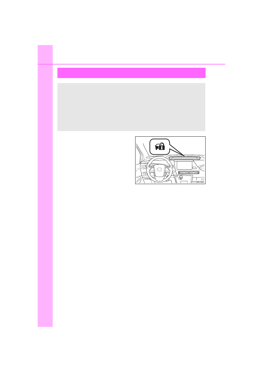
The  indicator  flashes  after  the
power switch has been turned off
to indicate that the system is oper-
ating.
The  indicator  stops  flashing  after
the power switch has been turned
to ACCESSORY  or  ON  mode  to
indicate that the system has been
canceled.

The vehicle’s keys have built-in transponder chips that prevent
the  fuel  cell  system  from  starting  if  a  key  has  not  been  previ-
ously registered in the vehicle’s on-board computer. 
Never leave the keys inside the vehicle when you leave the vehi-
cle.
This system is designed to help prevent vehicle theft but does
not guarantee absolute security against all vehicle thefts.

-------------------------------------------------------------------------------------------------------------------------------------------------------------

79

1-3. Theft deterrent system

1

Fo
r safety and securi

ty

MIRAI_OM_USA_OM62073U

System maintenance

The vehicle has a maintenance-free type immobilizer system.

Conditions that may cause the system to malfunction

If the grip portion of the key is in contact with a metallic object

If the key is in close proximity to or touching a key registered to the security
system (key with a built-in transponder chip) of another vehicle

Certification for the immobilizer system

For U.S.A.

l

-------------------------------------------------------------------------------------------------------------------------------------------------------------

80

1-3. Theft deterrent system

MIRAI_OM_USA_OM62073U

For Canada

WARNING

Certifications for the immobilizer system

Changes or modifications not expressly approved by the party responsible
for compliance could void the user’s authority to operate the equipment.

NOTICE

To ensure the system operates correctly

Do  not  modify  or  remove  the  system.  If  modified  or  removed,  the  proper
operation of the system cannot be guaranteed.

-------------------------------------------------------------------------------------------------------------------------------------------------------------

81

1-3. Theft deterrent system

1

Fo
r safety and securi

ty

MIRAI_OM_USA_OM62073U

Alarm

The alarm uses light and sound to give an alert when an intrusion is
detected.
The  alarm  is  triggered  in  the  following  situations  when  the  alarm  is
set:

A locked door or trunk is unlocked or opened in any way other than
using the entry function, wireless remote control or mechanical key.
(The doors will lock again automatically.)

The hood is opened.

Close  the  doors,  trunk  and  hood,
and lock all the doors. The system
will  be  set  automatically  after  30
seconds.

The  indicator  changes  from  being
on  to  flashing  when  the  system  is
set.

Do one of the following to deactivate or stop the alarm:

Unlock the doors or open the trunk. 

Turn  the  power  switch  to ACCESSORY  or  ON  mode,  or  start  the
fuel cell system. (The alarm will be deactivated or stopped after a
few seconds.)

The alarm

Setting the alarm system

Deactivating or stopping the alarm

-------------------------------------------------------------------------------------------------------------------------------------------------------------

82

1-3. Theft deterrent system

MIRAI_OM_USA_OM62073U

System maintenance

The vehicle has a maintenance-free type alarm system.

Items to check before locking the vehicle

To prevent unexpected triggering of the alarm and vehicle theft, make sure of
the following:

Nobody is in the vehicle.

The windows are closed before the alarm is set.

No valuables or other personal items are left in the vehicle.

Triggering of the alarm

The alarm may be triggered in the following situations:
(Stopping the alarm deactivates the alarm system.)

Alarm-operated door lock

In the following cases, depending on the situation, the door may automatically
lock to prevent improper entry into the vehicle:

When a person remaining in the vehicle unlocks the door and the alarm is
activated.

While the alarm is activated, a person remaining in the vehicle unlocks the
door.

When recharging or replacing the 12-volt battery

A  person  inside  the  vehicle  opens  a
door,  the  trunk  or  hood,  or  unlocks  the
vehicle using an inside lock button.

The  12-volt  battery  is  recharged  or
replaced  when  the  vehicle  is  locked.
(

P. 454)

NOTICE

To ensure the system operates correctly

Do  not  modify  or  remove  the  system.  If  modified  or  removed,  the  proper
operation of the system cannot be guaranteed.

-------------------------------------------------------------------------------------------------------------------------------------------------------------

83

1-3. Theft deterrent system

1

Fo
r safety and securi

ty

MIRAI_OM_USA_OM62073U

Theft prevention labels

These  labels  are  attached  to  the
vehicle  to  reduce  vehicle  theft  by
facilitating  the  tracing  and  recov-
ery  of  parts  from  stolen  vehicles.
Do  not  remove  under  penalty  of
law

-------------------------------------------------------------------------------------------------------------------------------------------------------------

84

1-3. Theft deterrent system

MIRAI_OM_USA_OM62073U

-------------------------------------------------------------------------------------------------------------------------------------------------------------

85

Fuel cell system

2

MIRAI_OM_USA_OM62073U

2.

Fuel cell vehicle

Fuel cell vehicle 

characteristics................... 86

Fuel cell vehicle 

precautions ....................... 90

Advice for driving fuel cell 

vehicles........................... 102

-------------------------------------------------------------------------------------------------------------------------------------------------------------

86

2. Fuel cell vehicle

MIRAI_OM_USA_OM62073U

Fuel cell vehicle characteristics

This diagram is for illustrative purposes only and may differ from the
actual vehicle.

Fuel  cell  vehicles  efficiently  use  electricity,  which  is  generated
by a chemical reaction between hydrogen and oxygen in a fuel
cell  stack,  and  electricity  charged  in  a  traction  battery  to  drive
the electric motor (traction motor). 
The  fuel  is  H

2

  (compressed  hydrogen  gas),  so  the  exhaust  is

only  water  and  water  vapor. As  they  do  not  release  emissions
such as CO

2

 (Carbon Dioxide) and NOx (Nitrogen Oxides), fuel

cell vehicles are environmentally friendly vehicles.

Fuel cell vehicle components

Fuel cell stack
Hydrogen tanks
Traction battery

Tailpipe
Fuel cell converter
Electric motor (traction motor)

-------------------------------------------------------------------------------------------------------------------------------------------------------------

87

2. Fuel cell vehicle

2

Fuel cell system

MIRAI_OM_USA_OM62073U

The  electric  motor  (traction  motor)  allows  smooth,  powerful  takeoff
and  acceleration.  This  vehicle  drives  similarly  to  a  gasoline  vehicle
without any special actions by the driver. (

P. 172) As there are no

engine  sounds  and  the  vehicle  is  quiet,  operation  noises  unique  to
fuel cell vehicle components may be heard. (

P. 88)

The  system  may  behave  differently  on  cold  days.  It  is  performing  a
special cold-start process to improve start-up performance. (

P. 189) 

Operation noises (

P. 88), purge process (

P. 189), etc., differ from

usual. However, this is not a malfunction.

Compressed hydrogen gas fuel can be filled at hydrogen stations.

Opening the fuel door (

P. 213)

Driving the vehicle

Fuel cell system

Fuel filling

-------------------------------------------------------------------------------------------------------------------------------------------------------------

88

2. Fuel cell vehicle

MIRAI_OM_USA_OM62073U

Sounds unique to the fuel cell vehicle

Due  to the design of  your  fuel cell vehicle, there  are  various  relays, valves
and pumps which under normal driving conditions will produce sounds. This
is a normal characteristic of the vehicle and does not indicate a malfunction.
Furthermore, way of hearing may differ based on usage environment or con-

dition.

Noticeable sounds

Source of the sounds

Clunking, clicking and clack-
ing

Operation  of  relays  and  hydrogen  tank
valves

Sounds may come from under the floor or
behind the rear seats.
(Sounds may be heard when starting the
fuel cell system.)

Knocking

The parking lock is engaged

Sounds  may  come  from  the  motor
compartment.
(Sounds may be heard when press the P
position  switch  or  stopping  the  fuel  cell
system.)

Whooshing, squealing

Gas  is  flowing  through  the  nozzle  and
valves

Sounds  may  come  from  behind  the  rear
seats, or from the dispenser hose/nozzle.
(Sounds  may  be  heard  when  filling  the
fuel.)

• High pitch sound
• Gurgle sound
• Pulsing sound

Operation of the pumps

Sounds  may  come  from  the  motor  com-
partment or under the front seats.
(In particular, sounds may be heard when
starting the fuel cell system, accelerating
from a stop, or press the H

2

O switch. The

sound may be louder when in Br mode or
when  the  vehicle  decelerates  during
dynamic radar cruise control.)

Humming sound

Operation of the pumps are speeding up

Sounds  may  come  from  the  motor  com-
partment or under the front seats.
(In particular, sounds may be heard when
accelerating or decelerating.)

Whooshing sound 

Operation of the hydrogen injector

Sounds  may  come  from  under  the  front
seats or behind the rear seats.
(In particular, sounds may be heard when
starting the fuel cell system, driving at low
speeds, or charging the traction battery.)

-------------------------------------------------------------------------------------------------------------------------------------------------------------

89

2. Fuel cell vehicle

2

Fuel cell system

MIRAI_OM_USA_OM62073U

Regenerative braking

In the following situations, the vehicle generates electricity from the decelera-
tion of the vehicle while driving.

The accelerator pedal is released while driving with the shift position in D.

The brake pedal is depressed while driving with the shift position in D.

Charging the traction battery

Because electricity generated by the fuel cell stack and regenerative braking
charges the traction battery, the battery does not need to be charged from an
outside source. However, if the vehicle is left parked for a long time, the trac-
tion battery will slowly discharge. For this reason, be sure to drive the vehicle
at least once every few months for at least 30 minutes or 10 miles (16 km). 
If the traction battery becomes fully discharged and you are unable to start
the fuel cell system, contact your Toyota dealer.

Charging the 12-volt battery

P. 454

Parking

Because there is no engine sound or vibration, it is easy to mistake the fuel
cell vehicle for being off when it is actually still running, as indicated by the
“READY” indicator being illuminated. For safety, make sure to always shift the
shift position to P and apply the parking brake when parked.

Maintenance, repair, recycling, and disposal

Contact your Toyota dealer regarding maintenance, repair, recycling, and dis-
posal. Do not dispose of the vehicle or any of its components yourself.

• Humming sound
• High pitch sound

Operation of the motor

Sounds  may  come  from  the  motor  com-
partment.
(In particular, sounds may be heard when
accelerating or decelerating.)

Blowing and draining sound

Exhaust water or air is being purged

Sounds  may  come  from  the  rear  of  the
vehicle.
May  also  occur  periodically  while  parked
when it is cold to prevent freezing.
(Sounds  may  be  heard  when  vehicle  is
stopped, fuel cell system is stopped, park-
ing.)

Noticeable sounds

Source of the sounds

-------------------------------------------------------------------------------------------------------------------------------------------------------------

90

2. Fuel cell vehicle

MIRAI_OM_USA_OM62073U

Fuel cell vehicle precautions

The  fuel  cell  vehicle  has  hydrogen  tanks  (10150 psi  [70 MPa,
714 kgf/cm

2

,  700 bar]),  fuel  cell  stack,  and  hydrogen  pipelines  as

hydrogen-related  components.  Pay  attention  to  all  warning  labels
attached to the vehicle.

This diagram is for illustrative purposes only and may differ from the
actual vehicle.

Hydrogen-related components

Warning label
Hydrogen detectors
Fuel cell stack

Hydrogen tanks
Hydrogen tank valves
Hydrogen pipelines

-------------------------------------------------------------------------------------------------------------------------------------------------------------

91

2. Fuel cell vehicle

2

Fuel cell system

MIRAI_OM_USA_OM62073U

The fuel cell vehicle has high-voltage components (about 650 V maxi-
mum)  such  as  a  fuel  cell  stack,  traction  battery,  power  control  unit,
high-voltage cables (which are distinguished from low-voltage cables
by their orange covers), electric motor (traction motor), etc., and high-
temperature parts such as the radiator for cooling. Pay attention to all
warning labels attached to the vehicle.

This diagram is for illustrative purposes only and may differ from the
actual vehicle.

High-voltage and high-temperature components

Warning label
Power control unit
High-voltage cables (orange)
Fuel cell stack
Traction battery
Service plug
Fuel cell converter

Electric motor (traction motor)
Air conditioning compressor
Radiator for inverter cooling
Radiator  for  fuel  cell  stack
cooling
Auxiliary inverter
Cabin coolant heater

-------------------------------------------------------------------------------------------------------------------------------------------------------------

92

2. Fuel cell vehicle

MIRAI_OM_USA_OM62073U

When a certain level of impact from an accident is detected, the fuel
cell system is shut down and the system shuts out the high voltage.
Also, the fuel supply is stopped from the hydrogen tank valves. If the
emergency shut off system activates, your vehicle will not restart. To
restart the fuel cell system, contact your Toyota dealer.

A  message  is  automatically  displayed  when  a  malfunction  occurs  in
the fuel cell system or an improper operation is attempted.
If a warning message is shown on
the multi-information display, read
the  message  and  follow  the
instructions. (

P. 426)

Fuel cell vehicles do not have engine sounds like gasoline vehicles.
Therefore, it makes an artificial noise at low speeds to notify pedestri-
ans and nearby vehicles that it is approaching. The sound varies with
speed and will stop when the vehicle exceeds approximately 15 mph
(25 km/h).

Emergency shut off system

Fuel cell warning message

Vehicle proximity notification system

-------------------------------------------------------------------------------------------------------------------------------------------------------------

93

2. Fuel cell vehicle

2

Fuel cell system

MIRAI_OM_USA_OM62073U

There is an air intake vent beside
the  rear  left  seat  for  the  purpose
of  cooling  the  traction  battery.  If
the  air  intake  vent  is  blocked,  it
could  lead  to  a  reduction  in  trac-
tion battery output.

If  a  warning  light  comes  on,  a  warning  message  is  displayed,  or  the
12-volt battery connection is disconnected

The fuel cell system may not be able to restart. 
If the “READY” indicator does not come on, even when the start procedure is
repeated, contact your Toyota dealer.

If  “Hydrogen  Leakage  Detected  Visit  Your  Dealer”  is  displayed  on  the
multi-information display

A small amount of hydrogen gas may be leaking. Have the vehicle inspected
immediately at the nearest Toyota dealer.

If “FC System Shutdown due to Hydrogen Leakage Stop Your Vehicle in
a Safe Place and Contact Your Dealer” is displayed on the multi-informa-
tion display

Hydrogen gas may be leaking.
When hydrogen gas is leaking or some other malfunction is detected: 

P. 98

The air conditioning system will shut off automatically.

Running out of fuel

When  the  vehicle  has  run  out  of  fuel  and  the  fuel  cell  system  cannot  be
started, refuel the vehicle until the low fuel level warning light (

P. 420) turns

off before trying to restart. It may not be able to restart if the refueled amount
is too low (less than about 2.7 lb. [1.2 kg]).

Traction battery air intake vent

-------------------------------------------------------------------------------------------------------------------------------------------------------------

94

2. Fuel cell vehicle

MIRAI_OM_USA_OM62073U

Fuel cell stack

Depending  on  the  usage  environment,  the  fuel  cell  power  output  may
decline over the life of the vehicle. However, this will have almost no effect
on driving performance.

In the following situations, the fuel cell power output may decline faster than
normal driving:
• Extended use in areas with high amounts of dust
• Extended use in areas with high levels of sulfur (such as volcanoes or hot

springs).

• Extended  use  in  areas  with  high  concentrations  of  the  following

substances: 
-Organic solvents, such as paint and thinner 
-Amine-related materials such as ammonia 
-Chlorinated substances such as salt air and snow-melting agent

However, upon returning to normal environment, the fuel cell power output
will recover over time.
• Salt water gets into the air cleaner filter 

It is recommended to replace the air cleaner filter and clean the surround-
ing components. Have the vehicle inspected at your Toyota dealer

• The number of times the fuel cell system is started and stopped is exces-

sively high

• Extended use in freezing temperatures

Hydrogen tanks

The hydrogen tanks are the high-pressure storage containers that are filled
with  compressed  hydrogen  gas. The  vehicle  can  be  refueled  at  hydrogen
stations.

The hydrogen tanks have an expiration date. Vehicles with expired hydro-
gen  tanks  must  not  be  driven  or  refueled  until  the  hydrogen  tanks  are
replaced. The expiration date is written on the inside of the fuel door. Con-
sult your Toyota dealer.

When disposing of the hydrogen tanks or the hydrogen tank valves, consult
your Toyota dealer for details.

-------------------------------------------------------------------------------------------------------------------------------------------------------------

95

2. Fuel cell vehicle

2

Fuel cell system

MIRAI_OM_USA_OM62073U

Fuel cell stack coolant

Fuel cell stack coolant uses a specifically-designed fluid with high electrical
insulation properties, in order to safely cool the high-voltage fuel cell stack.

Never add water or other coolants to the fuel cell stack cooling system, as
they will cause permanent damage.

Consult your Toyota dealer for replenishing or changing the fuel cell stack
coolant.

Ion filter

An ion filter is installed in the coolant lines for the fuel cell stack, in order to
maintain the normal insulation properties of the coolant.

It is necessary to periodically change the ion filter. (

P. 428) Contact your

Toyota dealer for this periodic maintenance.

Tailpipe

When  the  power  switch  is  turned  off  and  the  fuel  cell  system  is  stopped
(

P. 187) after driving, exhaust water is discharged. Be careful when stand-

ing behind the vehicle to avoid dripping or spraying.

It  is  possible  to  manually  purge  the  exhaust.  This  may  be  desirable,  for
instance,  before  parking  in  a  garage.  This  is  done  by  pressing  the  H

2

O

switch. (

P. 187)

On cold days, water vapor in the exhaust may appear as a white mist emit-
ted from the tailpipe. This is not a malfunction.

If the tailpipe is blocked, the fuel cell system will stop.

Hydrogen detectors

When  the  power  switch  is  turned  to  ON  mode,  the  hydrogen  detectors  are
activated.

-------------------------------------------------------------------------------------------------------------------------------------------------------------

96

2. Fuel cell vehicle

MIRAI_OM_USA_OM62073U

Power output restriction

When the power output is restricted, the vehicle may fail to accelerate or even
decelerate, even though the accelerator pedal is depressed. If a safe driving
speed cannot be maintained, stop the vehicle in a safe place away from the
traffic. This may be caused by the following conditions:

The  coolant  temperature  may  be  too  high. This  can  be  caused  by  driving
conditions such as repeated sudden acceleration and deceleration, continu-
ous  driving  on  an  incline,  continuous  driving  at  high  altitudes  with  a  high
load, etc. In such situations, the power output restriction indicator (amber) is
displayed  on  the  main  display,  “High  FC Temperature  Reduced  Power”  is
displayed  on  the  multi-information  display,  and  the  power  output  is
restricted. Once the coolant returns to normal temperature, the power out-
put will return to normal. (

P. 428)

The remaining fuel may be low. After the low fuel warning indicator comes
on, the output power will be gradually restricted in order to extend the possi-
ble  driving  distance.  Once  getting  to  this  point,  the  remaining  driving  dis-
tance possible is short. Immediately refill the vehicle with hydrogen.

On cold days, the low fuel warning indicator comes on faster than usual and
the output power is restricted.

Vehicle proximity notification system

In the following cases, the vehicle proximity notification system may be diffi-
cult to hear for people around.

In very noisy areas

In wind or rain

Also, because the vehicle proximity notification system is located in the front
of  the  vehicle,  it  may  be  more  difficult  to  hear  from  the  rear  of  the  vehicle
compared to the front.

Electromagnetic waves (EMF)

High-voltage parts and cables in fuel cell vehicles have an electromagnetic
shielding configuration, and therefore emit approximately the same amount
of  electromagnetic  waves  as  conventional  gasoline-powered  vehicles  or
home electronic appliances.

Your  vehicle  may  cause  sound  interference  in  some  third  party-produced
radio parts.

Traction battery

The traction battery has a limited service life. The lifespan of the traction bat-
tery can change according to driving style and driving conditions.

-------------------------------------------------------------------------------------------------------------------------------------------------------------

97

2. Fuel cell vehicle

2

Fuel cell system

MIRAI_OM_USA_OM62073U

Hydrogen Gas Characteristics

Hydrogen gas ignites more easily than gasoline. However, it is lighter than
air and disperses quickly. So even if hydrogen were to leak from the system,
it would quickly dilute until it is no longer flammable.

As with gasoline and natural gas, hydrogen gas is not dangerous if it is han-
dled properly. Thoroughly read and understand the characteristics shown in
the table below.

Hydrogen gas

LPG

(Liquid Petroleum 

Gas)

Gasoline

Normal state

Gaseous 
(Lighter than air)

Gaseous 
(Heavier than air)

Volatile 

liquid

(evaporates
easily) 
(Heavier than air)

Ease 

of

ignition

Easier 

than

gasoline

At  the  same  level
as gasoline

Ease 

of

accumulation

• Disperses

upward  and  is
diluted  to  safe
concentrations
in open air

• Does 

not

adhere 

to

clothing

• Spreads  on  the

ground or floor

• Does 

not

adhere 

to

clothing

• Spreads  on  the

ground or floor

• Adheres 

to

clothing

Detectability

• Due 

to 

its

colorless 

and

odorless  state,
difficult to detect
by sight or smell

• Vehicle

hydrogen
detectors 

will

display 

a

warning  on  the
multi-
information
display

• Detectable  by

odor  and  gas
leaking noise

• Detectable  by

color and odor

-------------------------------------------------------------------------------------------------------------------------------------------------------------

98

2. Fuel cell vehicle

MIRAI_OM_USA_OM62073U

Basic concepts of hydrogen safety

Prevent leakage
The  pipe  joints  of  the  hydrogen  pipelines  are  designed  to  prevent  leaks.
The joints are checked for gas leakage at every official vehicle inspection.

Detect to stop leakage
• The vehicle is equipped with hydrogen detectors. If the hydrogen detec-

tors detect a leak, the hydrogen tank valves automatically close to pre-
vent more hydrogen from escaping.

• The  vehicle  is  equipped  with  a  collision  sensor.  If  the  collision  sensor

detects a collision, the hydrogen tank valves automatically close to pre-
vent hydrogen gas from leaking from any damaged components.

Disperse the leaked hydrogen gas
The  hydrogen  tanks  and  pipelines  are  located  outside  of  the  passenger
compartment,  so  any  leaked  gas  will  disperse  into  the  atmosphere  by
design.

Eliminate sources of fire
No source of fire is located near the hydrogen pipelines by design.

WARNING

Hydrogen-related components

Never alter, customize, or disassemble any hydrogen-related parts.

The  hydrogen  tanks,  fuel  cell  stack,  hydrogen  pipelines,  and  connecting
components are filled with hydrogen gas. Do not remove or disassemble
these parts. Doing so can cause a hydrogen gas leak, resulting in fire or
explosion of the vehicle, which may result in death or serious injury.

When hydrogen gas leak or other malfunction is detected

If  a  large  amount  of  hydrogen  gas  leaking  is  noticed,  turn  off  the  power
switch, exit the vehicle, and stay far away from it. Display warning signs
and keep sources of fire away from the vehicle. If possible, get assistance.
When the above is done, immediately contact your Toyota dealer.

If  you  notice  gas  leaking  or  any  other  malfunction,  immediately  stop  the
vehicle  in  a  safe  and  well-ventilated  place,  exit  the  vehicle,  and  stay  far
away from it.

If a warning message is shown on the multi-information display, immedi-
ately stop the vehicle in a safe, well-ventilated place.

-------------------------------------------------------------------------------------------------------------------------------------------------------------

99

2. Fuel cell vehicle

2

Fuel cell system

MIRAI_OM_USA_OM62073U

WARNING

Tailpipe

Do not directly touch the water or steam coming out of the tailpipe. Doing
so may cause low-temperature burns.

The fuel cell vehicle generates water during power generation. The gener-
ated water discharged from the tailpipe is not suitable for drinking. Never
drink the water coming out of the tailpipe.

You may notice a strange odor from the tailpipe for a while after the pur-
chase of a new vehicle or after an extended period of non-use, but this is
not a malfunction. Also, the odor is harmless but it may be unpleasant, so
do not breathe in the exhaust.

High-voltage and high-temperature precautions

This vehicle is equipped with a high-voltage system. Follow the instructions
below as high-voltages can cause severe burns and electric shock that may
result in death or serious injury.

Never  touch,  disassemble,  remove,  or  replace  the  high-voltage  parts,
cables (orange), or connectors.

The  components  inside  the  motor  compartment  will  become  hot  during
operation. Be careful of both the high-voltage and high-temperature, and
always obey the warning labels on the vehicle.

Never  touch  the  service  plugs  that  are
installed  on  the  fuel  cell  stack  and  the
traction  battery.  The  service  plugs  are
used  to  block  high-voltages  from  the
fuel  cell  stack  and  the  traction  battery
during  maintenance  or  repair  at  your
Toyota dealer.

-------------------------------------------------------------------------------------------------------------------------------------------------------------

100

2. Fuel cell vehicle

MIRAI_OM_USA_OM62073U

WARNING

Precautions in case of an accident

In the event of an accident, observe the following precautions. Failure to do
so can cause fire or electric shocks, resulting in death or serious injury.

Stop the vehicle in a safe place to prevent subsequent accidents. Shift the
shift position to P and apply the parking brake.

Check for hydrogen gas leakage. 
Hydrogen leaks will cause a warning message to be shown on the multi-
information display. Larger leaks may also be audible.

If  a  large  amount  of  hydrogen  gas  leaking  is  noticed,  turn  off  the  power
switch, exit the vehicle, and stay far away from it. Display warning signs
and keep sources of fire away from the vehicle. If possible, get assistance.
When the above is done, immediately contact your Toyota dealer.

Do not touch the high-voltage parts, cables (orange), or connectors.

If  electric  wires  are  exposed  inside  or  outside  your  vehicle,  an  electric
shock may occur. Never touch exposed electric wires.

If a fluid leak occurs, do not touch the fluid as it may be the strong alkaline
electrolyte from the traction battery. If it comes into contact with your skin
or eyes, wash it off immediately with  a large amount of water, and seek
immediate medical attention.

In  case  of  a  vehicle  fire,  the  hydrogen  gas  in  the  hydrogen  tanks  is
released  via  the  hydrogen  tank  valves  toward  the  rear  of  the  vehicle
angled downward, in order to reduce the damage to the hydrogen tanks.
Keep away from the vehicle.

If a vehicle fire occurs, it can be extinguished with a Class A, B, or C fire
extinguisher. If using water, apply a large amount from a hydrant.

If your vehicle needs to be towed, do so with the front wheels lifted. If the
wheels  are  touching  the  ground,  the  electric  motor  (traction  motor)  may
continue to generate electricity. This may cause a fire.

-------------------------------------------------------------------------------------------------------------------------------------------------------------

101

2. Fuel cell vehicle

2

Fuel cell system

MIRAI_OM_USA_OM62073U

WARNING

Traction battery

Never resell, transfer, or modify the traction battery. To prevent accidents,
traction batteries that have been removed from disposed vehicle are col-
lected through Toyota dealers. Do not dispose of the traction battery your-
self. 
If  the  traction  battery  is  not  properly  collected,  the  following  may  occur,
resulting in death or serious injury:
• The traction battery may be illegally disposed or dumped, and it is haz-

ardous to the environment. Additionally, someone may touch a high-volt-
age part, resulting in an electric shock.

• The traction battery is intended to be used exclusively with your fuel cell

vehicle. If the traction battery is used outside of your vehicle or modified
in any way, accidents, such as electric shock, heat generation, smoke
generation, ignition, explosion and electrolyte leakage may occur.

In  particular,  reselling  or  transferring  the  traction  battery  exposes  the
receiving party to risks of accidents as they may not be aware of these
dangers. Make sure to inform them of the contents of this Owner’s Man-
ual.

If  your  vehicle  is  disposed  without  the  traction  battery  having  been
removed, there is a danger of serious electric shock in case high-voltage
parts,  cables,  or  their  connectors  are  touched.  When  disposing  of  your
vehicle, the traction battery must be disposed by your Toyota dealer, or a
qualified service shop. If the traction battery is not disposed of properly, it
may cause electric shock that can result in death or serious injury.

NOTICE

Traction battery air intake vent

If the traction battery output decreases due to the entry of dust or debris,
foreign material, a warning message is shown on the multi-information dis-
play. Have the vehicle inspected at your Toyota dealer.

Do not place objects where the air intake vent will be obstructed. This may
lead to a reduction in traction battery power output and damage.

Clean the air intake vent regularly to prevent clogging.

Do not allow water or objects to enter the air intake vent, as this may dam-
age the traction battery.

Traction Battery

Do not spill a large amount of water near the traction battery in the vehicle.
If water spills onto the traction battery, have the vehicle inspected at your
Toyota dealer.

-------------------------------------------------------------------------------------------------------------------------------------------------------------

102

2. Fuel cell vehicle

MIRAI_OM_USA_OM62073U

Advice for driving fuel cell vehicles

Fuel cell system indicator usage

Maintaining  the  fuel  cell  system  indicator  to  Eco  area  on  the
multi-information display can extend your driving range. (

P. 120)

Accelerator pedal/brake pedal operation

Drive the vehicle smoothly. Avoid abrupt acceleration and decelera-
tion.
Mild acceleration and deceleration can help curb wasteful fuel con-
sumption.

When braking

Make sure to depress the brake gently and allow for a long stopping
distance. This  enables  collection  of  more  electrical  energy  gener-
ated during deceleration.

Heavy traffic

Repeated  acceleration  and  deceleration  as  well  as  long  stops  at
traffic  lights,  will  decrease  fuel  economy.  Check  traffic  reports
ahead of time and avoid traffic jams as much as possible. If caught
in a traffic jam, gently release the brake pedal to allow the vehicle to
move  forward  slowly  while  avoiding  overuse  of  the  accelerator
pedal to help curb wasteful fuel consumption.

Driving with high power output

Similar to an electric vehicle, a fuel cell vehicle uses the most fuel in
high  output  driving  such  as  driving  on  a  steep  uphill  or  at  high
speeds. Moderate the vehicle speed and maintain a steady speed.

To  maximize  fuel  economy  and  range,  pay  attention  to  the  fol-
lowing:

-------------------------------------------------------------------------------------------------------------------------------------------------------------

103

2. Fuel cell vehicle

2

Fuel cell system

MIRAI_OM_USA_OM62073U

Using Eco drive mode

Using  Eco  drive  mode  (

P.  195)  makes  torque  generation  less

aggressive  than  normal  when  stepping  on  the  accelerator  pedal,
leading to improvement in fuel economy. 
Also, 

 is displayed on the air conditioning screen, indicating

the switch to ECO HEAT/COOL mode (

P. 308).

Air conditioning system on/off

Turn off the air conditioning system operation switch 

 except

when necessary to help curb fuel consumption.
In summer: When the ambient temperature is high, use the recircu-

lated air mode. This decreases the load on the air con-
ditioning system.

In winter:

Avoid excess heating. Use the seat heater to minimize
the need for cabin heating (

P. 316).

By  pushing 

,  ECO  HEAT/COOL  mode  is  turned  on.  This

helps curb fuel consumption even with the air conditioning system
turned on.

Checking tire inflation pressure

Make sure to check the tire inflation pressure frequently. Improper
tire inflation pressure can cause poor fuel economy. 
Additionally, snow tires have more rolling friction and their use on
dry roads lead to poor fuel economy. Use tires that are appropriate
for the season.

Luggage

Avoid carrying unnecessary luggage and unload excess weight in
order avoid poor fuel economy. Installing a large roof rack will also
reduce fuel economy.

-------------------------------------------------------------------------------------------------------------------------------------------------------------

104

2. Fuel cell vehicle

MIRAI_OM_USA_OM62073U

-------------------------------------------------------------------------------------------------------------------------------------------------------------

105

Instrument cluster

3

MIRAI_OM_USA_OM62073U

3.

Instrument cluster

Warning lights and 

indicators ........................ 106

Gauges and meters .......... 111
Multi-information display ... 117

-------------------------------------------------------------------------------------------------------------------------------------------------------------

106

3. Instrument cluster

MIRAI_OM_USA_OM62073U

Warning lights and indicators

The  units  used  on  the  meters  and  some  indicators  may  differ
depending on the target region.

The warning lights and indicators inform the driver of the status
of the vehicle’s various systems. 
For  the  purpose  of  explanation,  the  following  illustration  dis-
plays all warning lights and indicators illuminated.

-------------------------------------------------------------------------------------------------------------------------------------------------------------

107

3. Instrument cluster

3

Instrument clus

ter

MIRAI_OM_USA_OM62073U

Warning lights inform the driver of malfunctions in the indicated vehi-
cle’s systems.

Warning lights

*

1

Hydrogen leak warning 
light (

P. 418)

*

1

(Red/

Yellow)

Electric power steering 
system warning light 
(

P. 419)

*

1

(U.S.A.)

Brake system warning 
light (

P. 418)

(Yellow)

LDA indicator (

P. 419)

*

1

(Red)

(Canada)

Brake system warning 
light (

P. 418)

*

1

(Flashes)

PKSB OFF indicator 
(

P. 419)

Charging system 
warning light (

P. 418)

*

1

(Flashes 

or illumi-

nates)

PCS warning light 
(

P. 420)

*

1

High coolant 
temperature warning 
light (

P. 418)

*

1, 2

Slip indicator (

P. 420)

*

1

(Yellow)

Brake system warning 
light (

P. 418)

(U.S.A.)

Parking brake warning 
light (

P. 420)

*

1

SRS warning light 
(

P. 419)

(Canada)

Parking brake warning 
light (

P. 420)

*

1

(U.S.A.)

ABS warning light 
(

P. 419)

Open door warning light 
(

P. 420)

*

1

(Canada)

ABS warning light 
(

P. 419)

Low fuel level warning 
light (

P. 420)

-------------------------------------------------------------------------------------------------------------------------------------------------------------

108

3. Instrument cluster

MIRAI_OM_USA_OM62073U

*

1

: These lights turn on when the power switch is turned to ON mode to indi-

cate that a system check is being performed. They will turn off after the fuel
cell system is on, or after a few seconds. There may be a malfunction in a
system if a light does not come on, or turn off. Have the vehicle inspected
by your Toyota dealer.

*

2

: The light comes on to indicate a malfunction.

*

3

: This light illuminates on the multi-information display.

*

4

: This light illuminates on the main display.

Driver’s and front 
passenger’s seat belt 
reminder light (

P. 421)

*

3

Brake  Override  System/
Drive-Start Control/Park-
ing  Support  Brake  func-
tion (for static objects) (if
equipped) (

P. 421)

*

1

Master warning light 
(

P. 421)

*

4

(Blue)

Power restriction 
indicator (

P. 111)

*

1

Tire pressure warning 
light (

P. 421)

*

4

(Yellow)

Power restriction 
indicator (

P. 111, 428)

-------------------------------------------------------------------------------------------------------------------------------------------------------------

109

3. Instrument cluster

3

Instrument clus

ter

MIRAI_OM_USA_OM62073U

The indicators inform the driver of the operating state of the vehicle’s
various systems. 

Indicators

Turn signal indicator 
(

P. 199)

*

2, 3

PKSB OFF indicator 
(

P. 276)

(U.S.A.)

Headlight indicator 
(

P. 201)

Intuitive parking assist 
indicator (

P. 266)

(Canada)

Tail light indicator 
(

P. 201)

*

3, 4


Slip indicator (

P. 296)

Headlight high beam 
indicator (

P. 203)

*

2, 3

VSC OFF indicator 
(

P. 297)

Automatic High Beam 
indicator (

P. 205)

*

2, 3

PCS warning light 
(

P. 230)

“READY” indicator 
(

P. 186)

BSM indicators 
(

P. 287)

Dynamic radar cruise 
control indicator 
(

P. 253)

*

5, 6

BSM outside rear view 
mirror indicators 
(

P. 286)

Cruise control “SET” 
indicator (

P. 253)

Security indicator 
(

P. 78, 81)

Cruise control indicator 
(

P. 253)

Shift position indicator 
(

P. 193)

*

1

(Green)

LDA indicator (

P. 244)

*

7

ECO MODE indicator 
(

P. 195)

*

1

Steering control 
indicator (

P. 244)

*

7

POWER MODE 
indicator (

P. 195)

-------------------------------------------------------------------------------------------------------------------------------------------------------------

110

3. Instrument cluster

MIRAI_OM_USA_OM62073U

*

1

: Depending on the operating condition, the color and illuminating state of

the light change.

*

2

: The light turns on when the system is off.

*

3

: These lights turn on when the power switch is turned to ON mode to indi-

cate that a system check is being performed. They will turn off after the fuel
cell system is on, or after a few seconds. There may be a malfunction in a
system if a light does not come on, or turn off. Have the vehicle inspected
by your Toyota dealer.

*

4

: The light flashes to indicate that the system is operating.

*

5

: In order to confirm operation, the BSM outside rear view mirror indicators

illuminate in the following situations:

• When the power switch is turned to ON mode while the BSM settings are

set to ON.

• When the BSM settings are set to ON while the power switch is in ON

mode.

If the system is functioning correctly, the BSM outside rear view mirror indi-

cators will turn off after a few seconds.
If the BSM outside rear view  mirror  indicators do not illuminate or do not

turn off, there may be a malfunction in the system.
If this occurs, have the vehicle inspected by your Toyota dealer.

*

6

: This light illuminates on the outside rear view mirrors.

*

7

: This light illuminates on the main display.

Br mode indicator 
(

P. 195)

*

3

(U.S.A.)

“AIR BAG ON/OFF” 
indicator (

P. 49)

H

2

O indicator 

(

P. 187)

*

3

(Canada)

“AIR BAG ON/OFF” 
indicator (

P. 49)

WARNING

If a safety system warning light does not come on 

Should a safety system light such as the ABS and SRS warning lights not

come  on  when  you  start  the  fuel  cell  system,  this  could  mean  that  these

systems are  not available to  help protect  you in an  accident, which could

result in death or serious injury. Have the vehicle inspected by your Toyota

dealer immediately if this occurs.

-------------------------------------------------------------------------------------------------------------------------------------------------------------

111

3. Instrument cluster

3

Instrument clus

ter

MIRAI_OM_USA_OM62073U

Gauges and meters

Main display

Displays the speedometer, fuel gauge, etc. (

P. 111)

Multi-information display

Presents the driver with a variety of vehicle data.
Displays warning messages in case of a malfunction. (

P. 426)

Shift position indicator

Displays the selected shift position. (

P. 193)

Clock

P. 328

Fuel gauge
Displays  the  quantity  of  fuel
remaining  in  the  hydrogen
tanks.

ECO MODE indicator and POWER MODE indicator
Displays the selected driving mode. 

(

P. 195)

Main display

-------------------------------------------------------------------------------------------------------------------------------------------------------------

112

3. Instrument cluster

MIRAI_OM_USA_OM62073U

Power restriction indicator
Blue: The fuel cell system output power is restricted, because the

coolant temperature is low.

Amber: The fuel cell system output power is restricted, because the

coolant temperature is high.

Outside temperature
Displays the outside temperature within the range of -40°F (-40°C)
to 122°F (50°C).
Low  outside  temperature  indicator  flashes  when  the  ambient  tem-
perature is 37°F (3°C) or lower.
Driving range distance
Displays the estimated maximum distance that can be driven with
the quantity of fuel remaining.

• Displays  the  possible  driving  distance  computed  from  the  fuel

consumption  studied  from  the  driving  history  and  the  current
remaining  amount  of  fuel.  The  actual  possible  driving  distance
may  differ  as  fuel  consumption  changes,  depending  on  driving
environment (weather, traffic, etc.) and conditions (sudden accel-
eration, air conditioning, etc.).

• When  only  a  small  amount  of  fuel  is  added  to  the  hydrogen

tanks, the display may not be updated.

Speedometer
Displays the vehicle speed.
Odometer and trip meter 
Odometer: 
Displays the total distance the vehicle has been driven.
Trip meter: 
Displays the distance the vehicle has been driven since the meter
was last reset. 
Trip meters “A” and “B” can be used to record and display different
distances independently.
Distance after start: 
Displays the distance driven after the fuel cell system was started.
Blank: 
A blank is displayed.

-------------------------------------------------------------------------------------------------------------------------------------------------------------

113

3. Instrument cluster

3

Instrument clus

ter

MIRAI_OM_USA_OM62073U

Switches  between  odometer  and
trip meter displays. When the trip
meter  is  displayed,  pressing  and
holding  the  button  will  reset  the
trip meter.

The brightness of the Instrument panel lights can be adjusted.

Brighter
Darker

Changing the display

Instrument panel light control

-------------------------------------------------------------------------------------------------------------------------------------------------------------

114

3. Instrument cluster

MIRAI_OM_USA_OM62073U

Vehicles with RSA (Road Sign Assist)

For split screen on the main display, turn off the RSA function. 
(

P. 251)

Vehicles without RSA (Road Sign Assist)

For split screen on the main display, change the settings on the 
[Meter settings]. (

P. 124)

To toggle through the items, while in split screen, press 

 or 

 of

the meter control switches (

P. 118), select 

 on the main dis-

play, and press 

 or 

.

Fuel cell system indicator

Power meter

Current fuel consumption

Setting split screen on the main display

-------------------------------------------------------------------------------------------------------------------------------------------------------------

115

3. Instrument cluster

3

Instrument clus

ter

MIRAI_OM_USA_OM62073U

Traction battery status

The meters and display illuminate when

The power switch is in ON mode.

Instrument panel brightness adjustment

The instrument panel brightness levels when the tail lights are on and off can
be adjusted individually. However, when the surroundings are bright (daytime,
etc.), turning on the tail lights will not change the instrument panel brightness.
At this time, any adjustments made to the instrument panel brightness levels
will be applied to both settings at once.

Outside temperature display

In the following situations, the correct outside temperature may not be dis-
played, or the display may take longer than normal to change.
• When stopped, or driving at low speeds (less than 16 mph [25 km/h])
• When the outside temperature has changed suddenly (at the entrance/

exit of a garage, tunnel, etc.) 

When “--” or “E” is displayed, the system may be malfunctioning.
Take your vehicle to your Toyota dealer.

Liquid crystal display

Small  spots  or  light  spots  may  appear  on  the  display. This  phenomenon  is
characteristic of liquid crystal displays, and there is no problem continuing to
use the display.

Customization

The meter display can be customized on the multi-information display. 
(Customizable features: 

P. 490)

-------------------------------------------------------------------------------------------------------------------------------------------------------------

116

3. Instrument cluster

MIRAI_OM_USA_OM62073U

NOTICE

To prevent damage to the fuel cell system and its components

This  vehicle  is  equipped  with  high  coolant  temperature  warning  light
(

P. 418), instead of, coolant temperature gauge. 

The fuel cell system may be overheating if the high coolant temperature
warning  light  flashes  or  comes  on.  In  this  case,  immediately  stop  the
vehicle in a safe place, and check the fuel cell system after it has cooled
completely. 

-------------------------------------------------------------------------------------------------------------------------------------------------------------

117

3. Instrument cluster

3

Instrument clus

ter

MIRAI_OM_USA_OM62073U

Multi-information display

Displays  the  following  informa-
tion  when  an  icon  is  selected.
(

P. 118)

Some of the information may be
displayed 

automatically

depending on the situation.

Drive information

Select to display various drive data. (

P. 118)

Navigation system-linked display

Select to display the following navigation system-linked information.

• Route guidance
• Compass display (north-up display/heading-up display)

Audio system-linked display

Select to enable selection of an audio source or track on the display
using the meter control switches.

Driving assist systems display

Displays when each driving assistance system is used.

• Dynamic radar cruise control (

P. 253)

• LDA (Lane Departure Alert with steering control) (

P. 238)

Warning message display

Select to display warning messages and measures to be taken if a
malfunction is detected. (

P. 426)

Settings display

Select  to  change  the  meter  display  settings  and  the  operation  set-
tings of some vehicle functions. (

P. 124)

The multi-information display presents the driver with a variety
of vehicle data.

-------------------------------------------------------------------------------------------------------------------------------------------------------------

118

3. Instrument cluster

MIRAI_OM_USA_OM62073U

The  multi-information  display  is
operated  using  the  meter  control
switches.

Select an item/change pages
Enter/Set
Return  to  the  previous
screen

To  toggle  through  the  items,  press 

  or 

  of  the  meter  control

switches  (

P.  118),  select 

  [drive  information]  on  the  multi-

information display, and press 

 or 

.

Energy monitor

Displays fuel cell system status.

Operating the meter control switches

Drive information

When  the  vehicle  is  powered  by  the  fuel  cell
stack

When  the  vehicle  is  powered  by  the  traction
battery

When  the  vehicle  is  powered  by  the  fuel  cell
stack and traction battery

-------------------------------------------------------------------------------------------------------------------------------------------------------------

119

3. Instrument cluster

3

Instrument clus

ter

MIRAI_OM_USA_OM62073U

These images are examples only, and may vary slightly from actual
conditions.

When the vehicle is charging the traction bat-
tery

When there is no energy flow

Traction battery status

Low

Full

-------------------------------------------------------------------------------------------------------------------------------------------------------------

120

3. Instrument cluster

MIRAI_OM_USA_OM62073U

Fuel cell system indicator and ECO Score

The output power of the fuel cell system, regeneration level display,
and the ECO driving is scored and displayed.

Charge area
Shows  that  energy  is  being
recovered  via  the  regenera-
tive brake.
Eco area
Shows  that  the  vehicle  is
being  driven  in  an  Eco-
friendly manner.
Power area
Shows that an Eco-friendly driving range is being exceeded.
ECO Score
Displays the driving conditions in 5 stages, which are separated
in the 3 patterns of ECO Start, ECO Cruise and ECO Stop. Also,
each time the vehicle is stopped, that number is displayed. (The
number for each take off is reset and not counted)

By maintaining the indicator display in the ECO area or Charge
area, Eco-friendly driving is possible.

Charge area indicates regeneration

*

 status. Regenerated energy

will be used to charge the traction battery.

*

: When  used  in  this  manual,  “regeneration”  refers  to  the  conversion  of

energy created by the movement of the vehicle into electrical energy.

-------------------------------------------------------------------------------------------------------------------------------------------------------------

121

3. Instrument cluster

3

Instrument clus

ter

MIRAI_OM_USA_OM62073U

Fuel consumption record

To toggle through the items, press 

 on the meter control switches

(

P. 118) to select the tab and then press either 

 or 

.

1-minute fuel consumption

Average  fuel  consumption  in  the
past  15  minutes,  displayed  in
1-minute intervals

5-minute fuel consumption

Average  fuel  consumption  in  the
past  30  minutes,  displayed  in
5-minute intervals

Monthly fuel consumption

Average  fuel  consumption  over
the past 6 months

The  scale  of  the  vertical  axis  can
be changed by pressing 

 or 

of the meter control switches.

Press 

  on  the  meter  control

switches (

P. 118) to return.

-------------------------------------------------------------------------------------------------------------------------------------------------------------

122

3. Instrument cluster

MIRAI_OM_USA_OM62073U

Drive monitor

Driving time
Displays  the  amount  of  time
since  starting

*

1

  the  fuel  cell

system or resetting

*

2

.

Average vehicle speed
Displays the average vehicle
speed  since  starting

*

1

  the

fuel  cell  system  or  reset-
ting

*

2

.

Average fuel consumption
Displays the average fuel consumption since starting

*

1

 the fuel

cell system or resetting

*

2

.

*

1

: When the odometer, traveled distance since starting, or blank is dis-

played in the odometer and trip meter of the main display

*

2

: When trip meter A or trip meter B is displayed in the odometer and

trip meter of the main display

-------------------------------------------------------------------------------------------------------------------------------------------------------------

123

3. Instrument cluster

3

Instrument clus

ter

MIRAI_OM_USA_OM62073U

ECO diary

To toggle through the items, press 

 on the meter control switches

(

P. 118) to select the tab and then press either 

 or 

.

Daily history

Press  either 

  or 

  of  the

meter  control  switches  to  scroll
through the days displayed.

Monthly history

Press  either 

  or 

  of  the

meter  control  switches  to  scroll
through the months displayed.

Press 

 on the meter control switches (

P. 118) to return.

Power meter

Displays  the  output  power  and
regeneration  level  of  the  fuel  cell
system.

-------------------------------------------------------------------------------------------------------------------------------------------------------------

124

3. Instrument cluster

MIRAI_OM_USA_OM62073U

The settings of the following items can be changed, refer to P. 484.

For  functions  that  can  be  enabled  or  disabled,  the  function  switches
between on and off each time 

 is pressed.

Clock (

P. 328)

 Rounds to the nearest hour

 Time adjustment

LDA (Lane Departure Alert with steering control) (

P. 238)

Select to set up the following items.

 Steering assist function

 Alert sensitivity

 Vehicle sway warning function

 Sway sensitivity

PCS (Pre-Collision System) (

P. 226)

Select to set up the following items.

 PCS on/off

 PCS sensitivity


BSM (Blind Spot Monitor) (

P. 286)

Select to set up the BSM and RCTA function on/off.

 RSA (Road Sign Assist) (if equipped) (

P. 248)

Select to set up RSA (Road Sign Assist) on/off.


Parking  Support  Brake  function  (for  static  objects)  (if

equipped) (

P. 274)

Select  to  set  up  the  Parking  Support  Brake  function  (for  static
objects) on/off.

Intuitive parking assist (

P. 265)

Select to set up the following items.

 Intuitive parking assist on/off

 Intuitive parking assist buzzer volume

Setting display

-------------------------------------------------------------------------------------------------------------------------------------------------------------

125

3. Instrument cluster

3

Instrument clus

ter

MIRAI_OM_USA_OM62073U

 Units

Select to change the unit.


Meter settings

Select the menu to set up the following items (

P. 490)

• RSA notification method (if equipped)

Select to change the RSA notification method.

• RSA notification level (if equipped)

Select to change the RSA notification level.

• Time for exchanging the ion filter

Select to initialize the time for exchanging the ion filter.

• Language

Select to change the language on the display.

• Interruption display

Select to set the Interruption displays (navigation system route guid-
ance, Instrument panel brightness adjustment), which may appear in
some situations, on/off.

• Return to initial settings

Registered or changed meter settings will be deleted or returned to
their default setting.

• Main display split screen (if equipped)

Select to change the main display to split screen.

• Monthly history of fuel economy history

Select to clear the history.

• Daily history of ECO log

Select to clear the log.

• Monthly history of ECO log

Select to clear the log.

• Calendar date

Select to set the date.

• Erase screen

Select to display a blank screen.

-------------------------------------------------------------------------------------------------------------------------------------------------------------

126

3. Instrument cluster

MIRAI_OM_USA_OM62073U

Setting items

 [Meter settings] items are not selectable while driving and cannot be

operated.
Also, the settings screen is temporarily canceled in the following situations.
• A warning message is displayed.
• The vehicle starts off.

Settings for functions not equipped to the vehicle are not displayed.

When a function is turned off, the related settings for that function are not
selectable.

When the 12-volt battery terminal is disconnected and reconnected

The following data is reset when the 12-volt battery terminal is disconnected
and reconnected.

1-minute fuel consumption

5-minute fuel consumption

Driving time

Average vehicle speed

Average fuel consumption

Liquid crystal display

P. 115

NOTICE

During setting up the display

To  prevent  12-volt  battery  discharge,  ensure  that  the  fuel  cell  system  is
operating while setting up the display features.

-------------------------------------------------------------------------------------------------------------------------------------------------------------

127

4

Operation of

each component

MIRAI_OM_USA_OM62073U

4-1. Key information

Keys .................................. 128

4-2. Opening, closing and 

locking the doors

Doors ................................ 132
Trunk................................. 138
Smart key system ............. 143

4-3. Adjusting the seats

Front seats ........................ 151
Driving position memory ... 153
Head restraints.................. 158

4-4. Adjusting the steering 

wheel and mirrors

Steering wheel .................. 160
Inside rear view mirror ...... 162
Outside rear view 

mirrors............................. 164

4-5. Opening and closing 

the windows

Power windows ................. 167

-------------------------------------------------------------------------------------------------------------------------------------------------------------

128

4-1. Key information

MIRAI_OM_USA_OM62073U

Keys

The following keys are provided with the vehicle.

Electronic keys

• Operating the smart key system

(

P. 143)

• Operating  the  wireless  remote

control function

Mechanical keys
Key number plate

Locks all the doors (

P. 132)

Unlocks all the doors (

P. 132)

Pressing  the  button  unlocks  the
driver’s  door.  Pressing  the  button
again within 5 seconds unlocks the
other doors.

Opens the windows (

P. 132)

*

Opens the trunk (

P. 138)

Sounds the alarm (

P. 129)

*

: This setting must be customized at your Toyota dealer.

The keys

Wireless remote control

-------------------------------------------------------------------------------------------------------------------------------------------------------------

129

4-1. Key information

4

Op
eration

 o

f each

 compo

nen
t

MIRAI_OM_USA_OM62073U

To  take  out  the  mechanical  key,
slide  the  release  lever  and  take
the key out.

The  mechanical  key  can  only  be
inserted  in  one  direction,  as  the
key only has grooves on one side.
If  the  key  cannot  be  inserted  in  a
lock  cylinder,  turn  it  over  and  re-
attempt to insert it.
After  using  the  mechanical  key,  store  it  in  the  electronic  key.  Carry  the
mechanical key together with the electronic key. If the electronic key bat-
tery  is  depleted  or  the  entry  function  does  not  operate  properly,  you  will
need the mechanical key. (

P. 449)

Panic mode

When required to leave the vehicle’s key with a parking attendant

Set the luggage security system (

P. 139) on and lock the glove box (

P. 321)

as circumstances demand.
Remove the mechanical key for your own use and provide the attendant with
the electronic key only.

If you lose your mechanical keys

New genuine mechanical keys can be made by your Toyota dealer using the
other  mechanical  key  and  the  key  number  stamped  on  your  key  number
plate. Keep the plate in a safe place such as your wallet, not in the vehicle. 

When riding in an aircraft

When bringing an electronic key onto an aircraft, make sure you do not press
any button on the electronic key while inside the aircraft cabin. If you are car-
rying an electronic key in your bag, etc., ensure that the buttons are not likely
to be pressed accidentally. Pressing a button may cause the electronic key to
emit radio waves that could interfere with the operation of the aircraft.

Using the mechanical key

When 

  is  pressed  for  longer  than

about 1 second, an alarm will sound inter-
mittently and the vehicle lights will flash to
deter any person from trying to break into
or damage your vehicle.
To stop the alarm, press any button on the
electronic key.

-------------------------------------------------------------------------------------------------------------------------------------------------------------

130

4-1. Key information

MIRAI_OM_USA_OM62073U

Electronic key battery depletion

The standard battery life is 1 to 2 years.

If the battery becomes low, an alarm will sound in the cabin when the fuel
cell system stops. (

P. 426)

As the electronic key always receives radio waves, the battery will become
depleted even if the electronic key is not used. The following symptoms indi-
cate  that  the  electronic  key  battery  may  be  depleted.  Replace  the  battery
when necessary. (

P. 400)

• The smart key system or the wireless remote control does not operate.
• The detection area becomes smaller.
• The LED indicator on the key surface does not turn on.

To  avoid  serious  deterioration,  do  not  leave  the  electronic  key  within  3 ft.
(1 m) of the following electrical appliances that produce a magnetic field:
• TVs
• Personal computers
• Cellular phones, cordless phones and battery chargers
• Recharging cellular phones or cordless phones
• Table lamps
• Induction cookers

Replacing the battery

P. 400

Confirmation of the registered key number

The number of keys already registered to the vehicle can be confirmed. Ask
your Toyota dealer for details.

If a wrong key is used

The key cylinder rotates freely to isolate inside mechanism.

-------------------------------------------------------------------------------------------------------------------------------------------------------------

131

4-1. Key information

4

Op
eration

 o

f each

 compo

nen
t

MIRAI_OM_USA_OM62073U

NOTICE

To prevent key damage

Do not drop the keys, subject them to strong shocks or bend them.

Do not expose the keys to high temperatures for long periods of time.

Do not get the keys wet or wash them in an ultrasonic washer, etc.

Do not attach metallic or magnetic materials to the keys or place the keys
close to such materials.

Do not disassemble the keys.

Do not attach a sticker or anything else to the surface of the electronic key.

Do not place the keys near objects that produce magnetic fields, such as
TVs,  audio  systems  and  induction  cookers,  or  medical  electrical  equip-
ment, such as low-frequency therapy equipment.

Carrying the electronic key on your person

Carry the electronic key 3.9 in. (10 cm) or more away from electric appli-
ances  that  are  turned  on.  Radio  waves  emitted  from  electric  appliances
within 3.9 in. (10 cm) of the electronic key may interfere with the key, caus-
ing the key to not function properly.

In case of a smart key system malfunction or other key-related prob-
lems

Take your vehicle with all the electronic keys provided with your vehicle to
your Toyota dealer.

When an electronic key is lost

If the electronic key remains lost, the risk of vehicle theft increases signifi-
cantly.  Visit  your  Toyota  dealer  immediately  with  all  remaining  electronic
keys that were provided with your vehicle.

-------------------------------------------------------------------------------------------------------------------------------------------------------------

132

4-2. Opening, closing and locking the doors

MIRAI_OM_USA_OM62073U

Doors

Smart key system

Carry the electronic key to enable this function.

Grip the driver’s door handle
to  unlock  the  door.  Grip  the
front  passenger’s  door  han-
dle to unlock all the doors.*

Make  sure  to  touch  the  sensor
on the back of the handle.
The  doors  cannot  be  unlocked
for 3 seconds after the doors are
locked.

*

: The door unlock settings can be changed. (

P. 136)

Touch the lock sensor (the indentation on the surface of the door
handle) to lock the doors.

Check that the door is securely locked.

Wireless remote control

Locks all the doors

Check  that  the  door  is  securely
locked.

Unlocks all the doors

Pressing  the  button  unlocks  the
driver’s door. Pressing the button
again  within  3  seconds  unlocks
the other doors.
Press and hold to open the win-
dows.

*


*

: This setting must be customized at your Toyota dealer.

The  vehicle  can  be  locked  and  unlocked  using  the  entry  func-
tion, wireless remote control or door lock switch.

Unlocking and locking the doors from the outside

-------------------------------------------------------------------------------------------------------------------------------------------------------------

133

4-2. Opening, closing and locking the doors

4

Op
eration

 o

f each

 compo

nen
t

MIRAI_OM_USA_OM62073U

Operation signals

Doors: 
A buzzer sounds and the emergency flashers flash to indicate that the doors
have been locked/unlocked. (Locked: Once; Unlocked: Twice)
Windows: 
A buzzer sounds to indicate that the windows are opening.

Security feature

If a door is not opened within approximately 60 seconds after the vehicle is
unlocked, the security feature automatically locks the vehicle again.

When the door cannot be locked by the lock sensor on the surface of the
door handle

Door lock buzzer

If  an  attempt  to  lock  the  doors  is  made  when  a  door  is  not  fully  closed,  a
buzzer sounds continuously for 5 seconds. Fully close the door to stop the
buzzer, and lock the doors once more.

Setting the alarm

Locking the doors will set the alarm system. (

P. 81)

If the smart key system or the wireless remote control does not operate
properly

Use the mechanical key to lock and unlock the doors. (

P. 449)

Replace the key battery with a new one if it is depleted. (

P. 400)

When  the  door  cannot  be  locked  even  if
the lock sensor on the surface of the door
handle  is  touched  by  a  finger,  touch  the
lock sensor with the palm. 
When gloves are being worn, remove the
gloves.

-------------------------------------------------------------------------------------------------------------------------------------------------------------

134

4-2. Opening, closing and locking the doors

MIRAI_OM_USA_OM62073U

Door lock switches

Locks all the doors
Unlocks all the doors

Inside lock buttons

Locks the door
Unlocks the door

The  front  doors  can  be  opened
by  pulling  the  inside  handle
even  if  the  lock  buttons  are  in
the lock position.

Move the inside lock button to the lock position.
Close the door.

The door cannot be locked if the power switch is in ACCESSORY or
ON mode, or the electronic key is left inside the vehicle.

If the key is not detected correctly, the door may be locked.

Unlocking and locking the doors from the inside

Locking the doors from the outside without a key

1

2

-------------------------------------------------------------------------------------------------------------------------------------------------------------

135

4-2. Opening, closing and locking the doors

4

Op
eration

 o

f each

 compo

nen
t

MIRAI_OM_USA_OM62073U

The door cannot be opened from
inside the vehicle when the lock is
set.

Unlock
Lock

These locks can be set to prevent
children  from  opening  the  rear
doors.  Push  down  on  each  rear
door switch to lock both rear doors. 

The following functions can be set or canceled:

For instructions on customizing, refer to P. 485.

Rear door child-protector lock

Automatic door locking and unlocking systems

Function

Operation

Speed  linked  door  lock-
ing function

All  the  doors  are 

automatically 

locked  when  the

vehicle speed is approximately 12 mph (20 km/h)
or higher.

Shift position linked door
locking function

All  the  doors  are  automatically  locked  when
shifting the shift position to any positions other
than P.

Shift position linked door
unlocking function

All  the  doors  are  automatically  unlocked  when
shifting the shift position to P.

Driver’s door linked door
unlocking function

All  the  doors  are  automatically  unlocked  when
the driver’s door is opened.

-------------------------------------------------------------------------------------------------------------------------------------------------------------

136

4-2. Opening, closing and locking the doors

MIRAI_OM_USA_OM62073U

Switching the door unlock function

It is possible to set which doors the entry function unlocks using the wireless
remote control. 

Turn the power switch off.

When the indicator light on the key surface is not on, press and hold 

,

  or 

  for  approximately  5  seconds  while  pressing  and  holding

The setting changes each time an operation is performed, as shown below.
(When changing the setting continuously, release the buttons, wait for at least
5 seconds, and repeat step 

.)

To  prevent  unintended  triggering  of  the  alarm,  unlock  the  doors  using  the
wireless  remote  control  and  open  and  close  a  door  once  after  the  settings
have been changed. (If a door is not opened within 60 seconds after 

 is

pressed, the doors will be locked again and the alarm will automatically be
set.)
In case that the alarm is triggered, immediately stop the alarm. (

P. 81)

Impact detection door lock release system

In the event that the vehicle is subject to a strong impact, all the doors are
unlocked. Depending on the force of the impact or the type of accident, how-
ever, the system may not operate.

Using the mechanical key

The doors can also be locked and unlocked with the mechanical key. 
(

P. 449)

Open door warning buzzer

If the vehicle speed reaches 3 mph (5 km/h), the master warning light flashes
and a buzzer sounds to indicate that door(s) or the hood is not fully closed.
The open door(s) or hood is displayed on the multi-information display.

1

2

2

Multi-information 

display

Unlocking function

Beep

Holding  the  driver’s  door
handle  unlocks  only  the
driver’s door.

Exterior:  Beeps  3
times
Interior: Pings once

Holding  the  front  passen-
ger’s  door  handle  unlocks
all the doors.

Holding  either  front  door
handle  unlocks  all  the
doors.

Exterior: Beeps twice
Interior: Pings once

-------------------------------------------------------------------------------------------------------------------------------------------------------------

137

4-2. Opening, closing and locking the doors

4

Op
eration

 o

f each

 compo

nen
t

MIRAI_OM_USA_OM62073U

Conditions affecting the operation of the smart key system or wireless
remote control

P. 146

Customization

Settings (e.g. unlocking function using a key) can be changed. 
(Customizable features: 

P. 485)

WARNING

To prevent an accident

Observe the following precautions while driving the vehicle.
Failure to do so may result in a door opening and an occupant falling out,
resulting in death or serious injury.

Ensure that all doors are properly closed and locked.

Do not pull the inside handle of the doors while driving.
Be  especially  careful  for  the  front  doors,  as  the  doors  may  be  opened
even if the inside lock buttons are in locked position.

Set the rear door child-protector locks when children are seated in the rear
seats. 

When opening or closing a door

Check the surroundings of the vehicle such as whether the vehicle is on an
incline,  whether  there  is  enough  space  for  a  door  to  open  and  whether  a
strong wind is blowing. 
When opening or closing the door, hold the door handle tightly to prepare
for any unpredictable movement.

When using the wireless remote control and operating the power win-
dows

Operate the power window after checking to make sure that there is no pos-
sibility of any passenger having any of their body parts caught in the win-
dow. Also, do not allow children to operate the wireless remote control. It is
possible for children and other passengers to get caught in the power win-
dow.

-------------------------------------------------------------------------------------------------------------------------------------------------------------

138

4-2. Opening, closing and locking the doors

MIRAI_OM_USA_OM62073U

Trunk

Press the trunk opener switch.

Smart key system

While  carrying  the  electronic
key,  press  the  button  on  the
trunk lid.

When all the doors are unlocked
with  the  power  door  lock  sys-
tem,  the  trunk  can  be  opened
without  carrying  the  electronic
key.

Wireless remote control

Press and hold the switch.

The trunk can be opened using the trunk opener, entry function
or wireless remote control.

Opening the trunk from inside the vehicle

Opening the trunk from outside the vehicle

-------------------------------------------------------------------------------------------------------------------------------------------------------------

139

4-2. Opening, closing and locking the doors

4

Op
eration

 o

f each

 compo

nen
t

MIRAI_OM_USA_OM62073U

Using  the  trunk  grip,  lower  the
trunk without applying force to the
side  and  push  the  trunk  down
from the outside to close it.

To protect luggage stored in the trunk against theft, the luggage secu-
rity system can be set to on.
To  disable  the  trunk  opener
switch, turn the main switch in the
glove box off.

On
Off

When  the  main  switch  is  off,  the
trunk  lid  cannot  be  opened  even
with the wireless remote control or
the entry function.

When closing the trunk

Luggage security system

-------------------------------------------------------------------------------------------------------------------------------------------------------------

140

4-2. Opening, closing and locking the doors

MIRAI_OM_USA_OM62073U

Trunk light

The trunk light turns on when the trunk is opened.

Function to prevent the trunk being locked with the electronic key inside

When all doors are locked, closing the trunk lid with the electronic key left
inside the trunk will sound an alarm.
In this case, the trunk lid can be opened by pressing the trunk release but-
ton on the trunk lid.

If the spare electronic key is put in the trunk with all the doors locked, the
key  confinement  prevention  function  is  activated  so  the  trunk  can  be
opened.  In  order  to  prevent  theft,  take  all  electronic  keys  with  you  when
leaving the vehicle.

If the electronic key is put in the trunk with all the doors locked, the key may
not be detected depending on the location of the key and the surrounding
radio wave conditions. In this case, the key confinement prevention function
cannot  be  activated,  causing  the  doors  to  lock  when  the  trunk  is  closed.
Make sure to check where the key is before closing the trunk.

The key confinement prevention function cannot be activated if any one of
the doors is unlocked. In this case, open the trunk using the trunk opener
switch.

Internal trunk release lever

Using the mechanical key

The trunk can be also opened using the mechanical key. (

P. 449)

Open trunk warning buzzer

If the vehicle speed reaches 3 mph (5 km/h), the master warning light flashes
and a buzzer sounds to indicate that the trunk is not fully closed.

If the smart key system or the wireless remote control does not operate
properly

Use the mechanical key to unlock the trunk. (

P. 449)

Replace the key battery with a new one if it is depleted. (

P. 400)

When leaving a key to the vehicle with a parking attendant

P. 129

 Customization

The trunk unlocking operation can be changed. 
(Customizable features: 

P. 487)

The trunk lid can be opened by pulling the
glow-in-the-dark  lever  located  on  the
inside of the trunk lid upward.
The  lever  will  continue  to  glow  for  some
time after the trunk lid is closed.

-------------------------------------------------------------------------------------------------------------------------------------------------------------

141

4-2. Opening, closing and locking the doors

4

Op
eration

 o

f each

 compo

nen
t

MIRAI_OM_USA_OM62073U

P. 129

WARNING

Observe the following precautions.
Failure to do so may result in death or serious injury.

Before driving

Make sure that the trunk lid is fully closed. If the trunk lid is not fully closed,
it may open unexpectedly while driving and hit near-by objects or luggage
in the trunk may be thrown out, causing an accident.

Do not allow children to play in the trunk. 
If  a  child  is  accidentally  locked  in  the  trunk,  they  could  suffer  from  heat
exhaustion, suffocation or other injuries.

Do not allow a child to open or close the trunk lid. 
Doing  so  may  cause  the  trunk  lid  to  open  unexpectedly,  or  cause  the
child’s hands, head, or neck to be caught by the closing trunk lid.

Important points while driving

Never let anyone sit in the trunk. In the event of sudden braking or a colli-
sion, they are susceptible to death or serious injury.

-------------------------------------------------------------------------------------------------------------------------------------------------------------


Content      ..      1      2      3      ..