Toyota Land Cruiser (2020 year). Manual in english - part 8
 

  Index      Toyota     Toyota Land Cruiser (2020 year). Manual in english


Search            copyright infringement  


Content      ..     6      7      8      9     ..


Toyota Land Cruiser (2020 year). Manual in english - part 8


464

LC200_OM_OM60R53U_(U)

6-3. Do-it-yourself maintenance

Hood

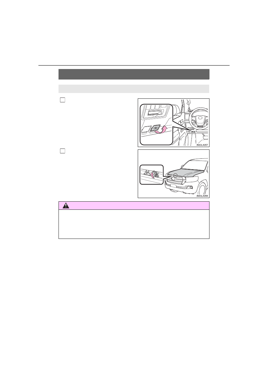
Pull the hood lock release lever.

The hood will pop up slightly.

Lift  the  hood  catch  and  lift  the
hood.

Release the lock from the inside of the vehicle to open the hood.

1

2

WARNING

Pre-driving check

Check that the hood is fully closed and locked.
If the hood is not locked properly, it may open while the vehicle is in motion
and cause an accident, which may result in death or serious injury.

-------------------------------------------------------------------------------------------------------------------------------------------------------------

465

LC200_OM_OM60R53U_(U)

6-3. Do-it-yourself maintenance

6

Mainten

ance an

d ca

re

Engine compartment

Power steering fluid reservoir

(

P. 473)

Engine oil level dipstick

(

P. 467)

Engine coolant reservoir

(

P. 470)

Cooling fans

(

P. 471)

Engine oil filler cap (

P. 468)

Brake fluid reservoir

(

P. 471)

Fuse box

(

P. 496)

Washer fluid tank (

P. 477)

Battery

(

P. 474)

Condenser

(

P. 471)

Radiator

(

P. 471)

1

2

3

4
5

6

7
8
9

10
11

-------------------------------------------------------------------------------------------------------------------------------------------------------------

466

LC200_OM_OM60R53U_(U)

6-3. Do-it-yourself maintenance

Removing the engine compartment cover

Installing the clips

Push up center portion
Insert
Press

Engine compartment cover

1
2
3

NOTICE

After installing an engine compartment cover

Make sure the cover is securely installed in its original position.

-------------------------------------------------------------------------------------------------------------------------------------------------------------

LC200_OM_OM60R53U_(U)

467

6-3. Do-it-yourself maintenance

6

Mainten

ance an

d ca

re

With the engine at operating temperature and turned off, check the oil
level on the dipstick.

Checking the engine oil

Park  the  vehicle  on  level  ground. After  warming  up  the  engine
and  turning  it  off,  wait  more  than  5  minutes  for  the  oil  to  drain
back into the bottom of the engine.
Holding a rag under the end,
pull the dipstick out.

Wipe the dipstick clean.
Reinsert the dipstick fully.
Holding a rag under the end, pull the dipstick out and check the
oil level.

Low
Normal
Excessive

The shape of the dipstick may
differ  depending  on  the  type
of vehicle or engine.

Wipe the dipstick and reinsert it fully.

Engine oil

1

2

3

4

5

1
2
3

6

-------------------------------------------------------------------------------------------------------------------------------------------------------------

468

LC200_OM_OM60R53U_(U)

6-3. Do-it-yourself maintenance

Adding engine oil

If  the  oil  level  is  below  or  near
the low level mark, add engine
oil of the same type as already
in the engine.

Make  sure  to  check  the  oil  type  and  prepare  the  items  needed
before adding oil.

Remove the oil filler cap by turning it counterclockwise.
Add engine oil slowly, checking the dipstick.
Install the oil filler cap by turning it clockwise.

Engine oil consumption

A certain amount of engine oil will be consumed while driving. In the following
situations,  oil  consumption  may  increase,  and  engine  oil  may  need  to  be
refilled in between oil maintenance intervals.

When the engine is new, for example directly after purchasing the vehicle or
after replacing the engine

If low quality oil or oil of an inappropriate viscosity is used 

When driving at high engine speeds or with a heavy load, when towing, or
when driving while accelerating or decelerating frequently

When leaving the engine idling for a long time, or when driving frequently
through heavy traffic

Engine oil selection

P. 570

Oil quantity (Low 

 Full) 1.6 qt. (1.5 L, 1.3 Imp.qt.)

Items

Clean funnel

1

2

3

-------------------------------------------------------------------------------------------------------------------------------------------------------------

LC200_OM_OM60R53U_(U)

469

6-3. Do-it-yourself maintenance

6

Mainten

ance an

d ca

re

After changing the engine oil

The engine oil maintenance data should be reset. Perform the following pro-
cedures:

Press 

 or 

 of the meter control switches, select 

.

Press 

  or 

  of  the  meter  control  switches,  select  “Oil  Maintenance”

and then press 

.

Select the “Yes” and press 

.

A message is displayed on the multi-information display.

WARNING

Used engine oil

Used  engine  oil  contains  potentially  harmful  contaminants  which  may
cause skin disorders such as inflammation or skin cancer, so care should
be taken to avoid prolonged and repeated contact. To remove used engine
oil from your skin, wash thoroughly with soap and water.

Dispose of used oil and filters only in a safe and acceptable manner. Do
not dispose of used oil and filters in household trash, in sewers or onto the
ground.  Call  your  Toyota  dealer,  service  station  or  auto  parts  store  for
information concerning recycling or disposal.

Do not leave used engine oil within the reach of children.

NOTICE

To prevent serious engine damage

Check the oil level on regular basis.

When replacing the engine oil

Be careful not to spill engine oil on the vehicle components.

Avoid overfilling, or the engine could be damaged.

Check the oil level on the dipstick every time you refill the vehicle.

Be sure the engine oil filler cap is properly tightened.

1

2

3

4

-------------------------------------------------------------------------------------------------------------------------------------------------------------

470

LC200_OM_OM60R53U_(U)

6-3. Do-it-yourself maintenance

The coolant level is satisfactory if it is between the “F” and “L” lines on
the reservoir when the engine is cold.

Reservoir cap
“F”
“L”

If  the  level  is  on  or  below  the  “L”
line, add coolant up to the “F” line.

Coolant selection

Only use “Toyota Super Long Life Coolant” or a similar high quality ethylene
glycol based non-silicate, non-amine, non-nitrite, and non-borate coolant with
long-life hybrid organic acid technology.
“Toyota  Super  Long  Life  Coolant”  is  a  mixture  of  50  %  coolant  and  50  %
deionized water. (Minimum temperature: -31

F [-35

C])

For more details about engine coolant, contact your Toyota dealer.

If the coolant level drops within a short time of replenishing

Visually check the radiator, hoses, engine coolant reservoir cap, radiator cap,
drain cock and water pump. If you cannot find a leak, have your Toyota dealer
test the cap and check for leaks in the cooling system.

Engine coolant

1
2
3

WARNING

When the engine is hot

Do not remove the radiator cap. 
The cooling system may be under pressure and may spray hot coolant if the
cap is removed, causing serious injuries, such as burns.

NOTICE

When adding coolant

Coolant is neither plain water nor straight antifreeze. The correct mixture of
water and antifreeze must be used to provide proper lubrication, corrosion
protection and cooling. Be sure to read the antifreeze or coolant label.

If you spill coolant

Be sure to wash it off with water to prevent it from damage to parts or paint.

-------------------------------------------------------------------------------------------------------------------------------------------------------------

LC200_OM_OM60R53U_(U)

471

6-3. Do-it-yourself maintenance

6

Mainten

ance an

d ca

re

Check the radiator and condenser and clear any foreign objects.
If  either of  the  above parts  is  extremely  dirty  or you  are not  sure of
their condition, have your vehicle checked by your Toyota dealer.

Checking fluid level

The brake fluid level should be
between  the  “MAX”  and  “MIN”
lines on the tank.

“MAX” line
“MIN” line

Adding fluid

Make sure to check the fluid type and prepare the necessary item.

Refilling brake fluid

Turn the engine switch off.
Depress the brake pedal more than 40 times.
Remove  the  reservoir  cap  by  hand. Add  brake  fluid  up  to  the
“MAX” line.

If you do not follow the procedure above, the reservoir may overflow.

Radiator and condenser

WARNING

When the engine is hot

Do not touch the radiator or condenser as they may be hot and cause seri-
ous injuries, such as burns.

Brake fluid

1
2

Fluid type

FMVSS No.116 DOT 3 or SAE J1703 brake fluid

Items

Clean funnel

1

2

3

-------------------------------------------------------------------------------------------------------------------------------------------------------------

472

LC200_OM_OM60R53U_(U)

6-3. Do-it-yourself maintenance

Brake fluid can absorb moisture from the air

Excess moisture in the fluid can cause a dangerous loss of braking efficiency.
Use only newly opened brake fluid.

WARNING

When filling the reservoir

Take care because brake fluid can harm your hands or eyes and damage
painted  surfaces.  If  fluid  gets  on  your  eyes,  flush  the  affected  area  with
clean water immediately. If you still experience discomfort, see a doctor.

NOTICE

If the fluid level is low or high

It is normal for the brake fluid level to go down slightly as the brake pads
wear or when the fluid level in the accumulator is high. If the reservoir needs
frequent refilling, it may indicate a serious problem.

-------------------------------------------------------------------------------------------------------------------------------------------------------------

LC200_OM_OM60R53U_(U)

473

6-3. Do-it-yourself maintenance

6

Mainten

ance an

d ca

re

Fluid level

The fluid level should be within the appropriate range.

Full (when hot)
Add fluid (when hot)
Full (when cold)
Add fluid (when cold)

Hot:

The vehicles has been driven around 50 mph (80 km/h) for
20 minutes, or slightly longer in frigid temperatures. 
(Fluid temperature, 140

F - 175

F [60

C - 80

C]).

Cold: The engine has not been run for about 5 hours. 

(Room temperature, 50

F - 85

F [10

C - 30

C]).

Checking the fluid level

Make sure to check the fluid type and prepare the necessary items.

Clean all dirt off the reservoir.
Remove the cap by turning it counterclockwise.
Wipe the dipstick clean.
Reinstall the cap and remove it again.
Check the fluid level.

Power steering fluid

1
2
3
4

Fluid type

Automatic transmission fluid DEXRON

®

 II or III

Items

Rag or paper, clean funnel (only for adding fluid)

1

2

3

4

5

-------------------------------------------------------------------------------------------------------------------------------------------------------------

474

LC200_OM_OM60R53U_(U)

6-3. Do-it-yourself maintenance

Check the battery as follows.

Battery exterior

Make  sure  that  the  battery  terminals  are  not  corroded  and  that
there are no loose connections, cracks, or loose clamps.

Terminals
Hold-down clamp

WARNING

When checking the reservoir

Take care as the reservoir may be hot.

NOTICE

When adding fluid

Avoid overfilling, or the power steering may be damaged.

After replacing the reservoir cap

Check the steering box case, vane pump and hose connections for leaks or
damage.

Battery

1
2

-------------------------------------------------------------------------------------------------------------------------------------------------------------

LC200_OM_OM60R53U_(U)

475

6-3. Do-it-yourself maintenance

6

Mainten

ance an

d ca

re

Before recharging

When recharging, the battery produces hydrogen gas which is flammable and
explosive. Therefore, observe the following before recharging:

If recharging with the battery installed on the vehicle, be sure to disconnect
the ground cable.

Make sure the power switch on the charger is off when connecting and dis-
connecting the charger cables to the battery.

After recharging/reconnecting the battery

The engine may not start. Follow the procedure below to initialize the system.

Shift the shift lever to P
Open and close any of the doors.
Restart the engine.

Unlocking the doors using the smart key system may not be possible imme-
diately  after  reconnecting  the  battery.  If  this  happens,  use  the  wireless
remote control or the mechanical key to lock/unlock the doors.

Start the engine with the engine switch in ACCESSORY mode. The engine
may  not  start  with  the  engine  switch  turned  off.  However,  the  engine  will
operate normally from the second attempt.

The engine switch mode is recorded by the vehicle. If the battery is recon-
nected, the vehicle will return the engine switch mode to the status it was in
before  the  battery  was  disconnected.  Make  sure  to  turn  off  the  engine
before disconnect the battery. Take extra care when connecting the battery
if the engine switch mode prior to discharge is unknown.

If the engine will not start even after multiple attempts at both methods, con-
tact your Toyota dealer.

WARNING

Chemicals in the battery

Batteries  contain  poisonous  and  corrosive  sulfuric  acid  and  may  produce
hydrogen gas which is flammable and explosive. To reduce the risk of death
or  serious  injury,  take  the  following  precautions  while  working  on  or  near
battery:

Do not cause sparks by touching the battery terminals with tools.

Do not smoke or light a match near the battery.

Avoid contact with eyes, skin and clothes.

Never inhale or swallow electrolyte.

Wear protective safety glasses when working near the battery.

Keep children away from the battery.

Where to safely charge the battery

Always charge the battery in an open area. Do not charge the battery in a
garage or closed room where there is not sufficient ventilation.

1

2

3

-------------------------------------------------------------------------------------------------------------------------------------------------------------

476

LC200_OM_OM60R53U_(U)

6-3. Do-it-yourself maintenance

WARNING

How to recharge the battery

Only  perform  a  slow  charge  (5A  or  less).  The  battery  may  explode  if
charged at a quicker rate.

Emergency measures regarding electrolyte

If electrolyte gets in your eyes
Flush your eyes with clean water for at least 15 minutes and get immedi-
ate medical attention. If possible, continue to apply water with a sponge or
cloth while traveling to the nearest medical facility.

If electrolyte gets on your skin
Wash the affected area thoroughly. If you feel pain or burning, get medical
attention immediately.

If electrolyte gets on your clothes
It can soak through clothing on to your skin. Immediately take off the cloth-
ing and follow the procedure above if necessary.

If you accidentally swallow electrolyte
Drink a large quantity of water or milk. Get emergency medical attention
immediately.

NOTICE

When recharging the battery

Never  recharge  the  battery  while  the  engine  is  running. Also,  be  sure  all
accessories are turned off.

-------------------------------------------------------------------------------------------------------------------------------------------------------------

LC200_OM_OM60R53U_(U)

477

6-3. Do-it-yourself maintenance

6

Mainten

ance an

d ca

re

If any washer does not work or the
warning message appears on the
multi-information 

display, 

the

washer  tank  may  be  empty. Add
washer fluid.

Washer fluid

WARNING

When adding washer fluid

Do not add washer fluid when the engine is hot or running as washer fluid
contains alcohol and may catch fire if spilled on the engine etc.

NOTICE

Do not use any fluid other than washer fluid

Do not use soapy water or engine antifreeze instead of washer fluid. 
Doing so may cause streaking on the vehicle’s painted surfaces, as well as
damaging the pump leading to problems of the washer fluid not spraying.

Diluting washer fluid

Dilute washer fluid with water as necessary. 
Refer to the freezing temperatures listed on the label of the washer fluid bot-
tle.

-------------------------------------------------------------------------------------------------------------------------------------------------------------

478

LC200_OM_OM60R53U_(U)

6-3. Do-it-yourself maintenance

Tires

Check if the treadwear indicators are showing on the tires. Also check
the tires for uneven wear, such as excessive wear on one side of the
tread. Check the spare tire condition and pressure if not rotated.

New tread
Worn tread
Treadwear indicator

The  location  of  treadwear  indicators  is  shown  by  the  “TWI”  or  “

mark, etc., molded into the sidewall of each tire.
Replace the tires if the treadwear indicators are showing on a tire.

Rotate  the  tires  in  the  order
shown.

To equalize tire wear and extend

tire life, Toyota recommends that

tire  rotation  is  carried  out  at  the

same interval as tire inspection.
Do  not  fail  to  initialize  the  tire

pressure  warning  system  after

tire rotation.

Replace or rotate tires in accordance with maintenance sched-
ules and treadwear.

Checking tires

Tire rotation

1
2
3

Front

-------------------------------------------------------------------------------------------------------------------------------------------------------------

LC200_OM_OM60R53U_(U)

479

6-3. Do-it-yourself maintenance

6

Mainten

ance an

d ca

re

Your Toyota is equipped with a tire pressure warning system that uses
tire pressure warning valves and transmitters to detect low tire infla-
tion pressure before serious problems arise.

If the tire pressure drops below a predetermined level, the driver is
warned by a screen display and a warning light. (

P. 527)

The  tire  pressure  detected  by
the  tire  pressure  warning  sys-
tem  can  be  displayed  on  the
multi-information display.

Installing tire pressure warning valves and transmitters

When  replacing  tires  or  wheels,  tire  pressure  warning  valves  and
transmitters must also be installed.
When  new  tire  pressure  warning  valves  and  transmitters  are
installed,  new  ID  codes  must  be  registered  in  the  tire  pressure
warning  computer  and  the  tire  pressure  warning  system  must  be
initialized.  Have  tire  pressure  warning  valve  and  transmitter  ID
codes registered by your Toyota dealer.

Initializing the tire pressure warning system

The tire pressure warning system must be initialized in the fol-
lowing circumstances:

When rotating the tires.

When the tire pressure warning system is initialized, the current tire
inflation pressure is set as the pressure benchmark.

Tire pressure warning system

-------------------------------------------------------------------------------------------------------------------------------------------------------------

480

LC200_OM_OM60R53U_(U)

6-3. Do-it-yourself maintenance

How to initialize the tire pressure warning system

Park the vehicle in safe place and turn the engine switch off.

Initialization cannot be performed while the vehicle is moved.

Adjust the tire inflation pressure to the specified cold tire inflation
pressure level. (

P. 574)

Make sure to adjust the tire pressure to the specified cold tire infla-

tion  pressure  level.  The  tire  pressure  warning  system  will  operate

based on this pressure level.

Turn the engine switch to IGNITION ON mode.
Press and hold the tire pres-
sure  warning  reset  switch
until  the  tire  pressure  warn-
ing light blinks slowly 3 times.

“--” will be displayed for inflation pressure of each tire on the multi-

information  display  while  the  tire  pressure  warning  system  deter-

mines the position on the multi-information display.
When  position  of  each  tire  is  determined,  the  inflation  pressure  of

each tire will be displayed on the multi-information display. 

Drive the vehicle at approximately 25 mph (40 km/h) or more for
approximately 10 to 30 minutes.

When initialization is complete, the inflation pressure of each tire will

be displayed on the multi-information display.
Depending  on  the  vehicle  and  driving  conditions,  initialization  may

take up to approximately 1 hour to complete.

Registering ID codes

The tire pressure warning valve and transmitter is equipped with a
unique ID code. When replacing a tire pressure warning valve and
transmitter, it is necessary to register the ID code. Have the ID code
registered by your Toyota dealer.

1

2

3

4

5

-------------------------------------------------------------------------------------------------------------------------------------------------------------

LC200_OM_OM60R53U_(U)

481

6-3. Do-it-yourself maintenance

6

Mainten

ance an

d ca

re

When to replace your vehicle’s tires

Tires should be replaced if:

The treadwear indicators are showing on a tire.

You  have  tire  damage  such  as  cuts,  splits,  cracks  deep  enough  to

expose the fabric, and bulges indicating internal damage

A tire goes flat repeatedly or cannot be properly repaired due to the size

or location of a cut or other damage

If you are not sure, consult with your Toyota dealer.

Replacing tires and wheels

If the ID code of the tire pressure warning valve and transmitter is not reg-

istered, the tire pressure warning system will not work properly. After driv-

ing  for  about  20  minutes,  the  tire  pressure  warning  light  blinks  for  1

minute and stays on to indicate a system malfunction.

Tire life

Any tire over 6 years old must be checked by a qualified technician even

if it has seldom or never been used or damage is not obvious.

Routine tire inflation pressure checks

The  tire  pressure  warning  system  does  not  replace  routine  tire inflation

pressure  checks.  Make  sure  to  check  tire  inflation  pressure  as  part  of

your routine of daily vehicle checks.

Maximum load of tire

Check that the number given by dividing the maximum load by 1.10 of the

replacement  tire  is  greater  than  1/2  of  the  Gross Axle  Weight  Ratings

(GAWR) of either the front axle or the rear axle, whichever is greater.
For  the  GAWR,  see  the  Certification

Label. For the maximum load of the tire,

see the load limit at maximum cold tire

inflation  pressure  mentioned  on  the

sidewall of the tire. (

P. 579)

-------------------------------------------------------------------------------------------------------------------------------------------------------------

482

LC200_OM_OM60R53U_(U)

6-3. Do-it-yourself maintenance

Tire types

Summer tires
Summer tires are high-speed performance tires best suited to highway

driving under dry conditions. Since summer tires do not have the same

traction  performance  as  snow  tires,  summer  tires  are  inadequate  for

driving  on  snow-covered  or  icy  roads.  For  driving  on  snow-covered

roads or icy roads, the use of snow tires is recommended. When install-

ing snow tires, be sure to replace all four tires.

All season tires
All season tires are designed to provide better traction in snow and to

be  adequate  for  driving  in  most  winter  conditions  as  well  as  for  use

year-round. All  season  tires,  however,  do  not  have  adequate  traction

performance compared with snow tires in heavy or loose snow. Also, all

season tires fall short in acceleration and handling performance com-

pared with summer tires in highway driving.

Snow tires
For driving on snow-covered roads or icy roads, we recommend using

snow tires. If you need snow tires, select tires of the same size, con-

struction and load capacity as the originally installed tires. Since your

vehicle  has  radial  tires  as  original  equipment,  make  sure  your  snow

tires also have radial construction. Do not install studded tires without

first  checking  local  regulations  for  possible  restrictions.  Snow  tires

should be installed on all wheels. (

P. 385)

When rotating the tires

Make sure that the engine switch is off. If the tires are rotated while the

engine switch is in IGNITION ON mode, the tire position information will

not be updated.
If this accidentally occurs, either turn the engine switch to off and then to

IGNITION ON mode, or initialize the system after checking that the tire

pressure is properly adjusted.

-------------------------------------------------------------------------------------------------------------------------------------------------------------

LC200_OM_OM60R53U_(U)

483

6-3. Do-it-yourself maintenance

6

Mainten

ance an

d ca

re

If the tread on snow tires wears down below 0.16 in. (4 mm)

The effectiveness of the tires as snow tires is lost.

Initializing the tire pressure warning system

initialize the system with the tire inflation pressure adjusted to the speci-

fied level.

Situations in which the tire pressure warning system may not oper-

ate properly

In the following cases, the tire pressure warning system may not operate

properly.
• If non-genuine Toyota wheels are used. 

• A tire has been replaced with a tire that is not an OE (Original Equip-

ment) tire.

• A tire has been replaced with a tire that is not of the specified size.

• Tire chains etc. are equipped.

• An auxiliary-supported run-flat tire is equipped.

• If a window tint that affects the radio wave signals is installed.

• If there is a lot of snow or ice on the vehicle, particularly around the

wheels or wheel housings.

• If  the  spare  tire  is  in  a  location  subject  to  poor  radio  wave  signal

reception.

• If a large metallic object which can interfere  with signal reception is

put near the spare tire.

• If tires not equipped with the tire pressure warning valves and trans-

mitters are used.

• If the ID code on the tire pressure warning valves and transmitters is

not registered in the tire pressure warning computer.

Performance may be affected in the following situations.
• Near a TV tower, electric power plant, gas station, radio station, large

display, airport or other facility that generates strong radio waves or

electrical noise

• When  carrying  a  portable  radio,  cellular  phone,  cordless  phone  or

other wireless communication device

When the vehicle is parked, the time taken for the warning to start or go

off could be extended.

When tire inflation pressure declines rapidly for example when a tire has

burst, the warning may not function.

-------------------------------------------------------------------------------------------------------------------------------------------------------------

484

LC200_OM_OM60R53U_(U)

6-3. Do-it-yourself maintenance

The initialization operation

Make sure to carry out initialization after adjusting the tire inflation pres-

sure. Also, make sure the tires are cold before carrying out initialization

or tire inflation pressure adjustment.

If you have accidentally turned the engine switch off during initialization,

it  is  not  necessary  to  press  the  reset  switch  again  as  initialization  will

restart automatically when the engine switch has been turned to IGNI-

TION ON mode for the next time.

If you accidentally press the reset switch when initialization is not neces-

sary,  adjust  the  tire  inflation  pressure  to  the  specified  level  when  the

tires are cold, and conduct initialization again.

While the position of each tire is being determined and the inflation pres-

sures  are  not  being  displayed  on  the  multi-information  display,  if  the

inflation pressure of a tire drops, the tire pressure warning light will come

on.

Warning performance of the tire pressure warning system

The  warning  of  the  tire  pressure  warning  system  will  change  in  accor-

dance with the conditions under which it was initialized. For this reason,

the system may give a warning even if the tire pressure does not reach a

low enough level, or if the pressure is higher than the pressure that was

adjusted to when the system was initialized.

When initialization of the tire pressure warning system has failed

Initialization  may  take  longer  to  complete  if  the  vehicle  is  driven  on  an

unpaved  road.  When  performing  initialization,  drive  on  a  paved  road  if

possible. Depending on the driving environment and condition of the tires,

initialization will be completed in approximately 10 minutes. If initialization

is not complete after driving approximately 10 minutes, continue driving

for a while.
If the inflation of each tire is not displayed after driving for approximately 1

hour, perform the following procedure.

Park  the  vehicle  in  a  safe  place  for  approximately  20  minutes.  Then

drive  straight  (with  occasional  left  and  right  turns)  at  approximately

25 mph (40 km/h) or more for approximately 10 to 20 minutes.

However, in the following situations, the tire inflation pressure will not be

recorder and the system will not operate properly. Perform initialization.

When operating the tire pressure warning reset switch, the tire pressure

warning light does not blink 3 times.

After performing initialization, the tire pressure warning light blinks for 1

minute then stays on after driving for about 20 minutes.

If the inflation pressure of each tire is still not displayed, have the vehicle

inspected by your Toyota dealer.

-------------------------------------------------------------------------------------------------------------------------------------------------------------

LC200_OM_OM60R53U_(U)

485

6-3. Do-it-yourself maintenance

6

Mainten

ance an

d ca

re

Tire pressure warning system certification

FCC ID: PAXPMVC015
NOTE
This device complies with part 15 of the FCC Rules. Operation is subject to
the following two conditions: (1) This device may not cause harmful interfer-
ence,  and  (2)  this  device  must  accept  any  interference  received,  including
interference that may cause undesired operation.
FCC WARNING
Changes or modifications not expressly approved by the party responsible for
compliance could void the user’s authority to operate the equipment.

WARNING

Tire pressure warning system operation

The tire pressure warning system may not provide warning immediately

if a tire bursts or if sudden air leakage occurs.

When inspecting or replacing tires

Observe the following precautions to prevent accidents. 

Failure to do so may cause damage to parts of the drive train as well as

dangerous  handling  characteristics,  which  may  lead  to  an  accident

resulting in death or serious injury.

Do not mix tires of different makes, models or tread patterns.

Also, do not mix tires of remarkably different treadwear.

Do not use tire sizes other than those recommended by Toyota.

Do not mix differently constructed tires (radial, bias-belted or bias-ply

tires).

Do not mix summer, all season and snow tires.

Do not use tires that have been used on another vehicle.

Do not use tires if you do not know how they were used previously.

When initializing the tire pressure warning system

Do  not  operate  the  tire  pressure  warning  reset  switch  without  first

adjusting the tire inflation pressure to the specified level. Otherwise, the

tire  pressure  warning  light  may  not  come  on  even  if  the  tire  inflation

pressure  is  low,  or  it  may  come  on  when  the  tire  inflation  pressure  is

actually normal.

-------------------------------------------------------------------------------------------------------------------------------------------------------------

486

LC200_OM_OM60R53U_(U)

6-3. Do-it-yourself maintenance

NOTICE

Repairing or replacing tires, wheels, tire pressure warning valves,

transmitters and tire valve caps

When removing or fitting the wheels, tires or the tire pressure warning

valves  and  transmitters,  contact  your Toyota  dealer  as  the  tire  pres-

sure warning valves and transmitters may be damaged if not handled

correctly.

Make sure to install the tire valve caps. If the tire valve caps are not

installed,  water  could  enter  the  tire  pressure  warning  valves  and  the

tire pressure warning valves could be bound.

When replacing tire valve caps, do not use tire valve caps other than

those specified. The cap may become stuck.

To avoid damage to the tire pressure warning valves and transmit-

ters

When  a  tire  is  repaired  with  liquid  sealants,  the  tire  pressure  warning

valve  and  transmitter  may  not  operate  properly.  If  a  liquid  sealant  is

used, contact your Toyota dealer or other qualified service shop as soon

as possible. Make sure to replace the tire pressure warning valve and

transmitter when replacing the tire. (

P. 479)

Driving on rough roads

Take particular care when driving on roads with loose surfaces or pot-

holes.

These conditions may cause losses in tire inflation pressure, reducing

the  cushioning  ability  of  the  tires.  In  addition,  driving  on  rough  roads

may  cause  damage  to  the  tires  themselves,  as  well  as  the  vehicle’s

wheels and body.

If tire inflation pressure of each tire becomes low while driving

Do not continue driving, or your tires and/or wheels may be ruined.

-------------------------------------------------------------------------------------------------------------------------------------------------------------

487

LC200_OM_OM60R53U_(U)

6-3. Do-it-yourself maintenance

6

Mainten

ance an

d ca

re

Tire inflation pressure

The  recommended  cold  tire  infla-
tion pressure and tire size are dis-
played  on  the  tire  and  loading
information label. (

P. 574)

Tire inflation pressure

-------------------------------------------------------------------------------------------------------------------------------------------------------------

488

LC200_OM_OM60R53U_(U)

6-3. Do-it-yourself maintenance

Tire valve
Tire pressure gauge

Remove the tire valve cap.
Press the tip of the tire pressure gauge onto the tire valve.
Read the pressure using the gauge gradations.
If the tire inflation pressure is not at the recommended level, adjust
the pressure.
If you add too much air, press the center of the valve to deflate.
After  completing  the  tire  inflation  pressure  measurement  and
adjustment, apply soapy water to the valve and check for leakage.
Put the tire valve cap back on.

Tire inflation pressure check interval

You should check tire inflation pressure every two weeks, or at least once

a month. Do not forget to check the spare.

Effects of incorrect tire inflation pressure

Driving with incorrect tire inflation pressure may result in the following:

Reduced fuel economy

Reduced driving comfort and poor handling

Reduced tire life due to wear

Reduced safety

Damage to the drive train

If a tire needs frequent inflating, have it checked by your Toyota dealer.

Inspection and adjustment procedure

1
2

1

2

3

4

5

6

-------------------------------------------------------------------------------------------------------------------------------------------------------------

LC200_OM_OM60R53U_(U)

489

6-3. Do-it-yourself maintenance

6

Mainten

ance an

d ca

re

Instructions for checking tire inflation pressure

When checking tire inflation pressure, observe the following:

Check only when the tires are cold.

If your vehicle has been parked for at least 3 hours and has not been

driven for more than 1 mile or 1.5 km, you will get an accurate cold tire

inflation pressure reading.

Always use a tire pressure gauge.

It is difficult to judge if a tire is properly inflated based only on its appear-

ance.

It  is  normal  for  the  tire  inflation  pressure  to  be  higher  after  driving  as

heat is generated in the tire. Do not reduce tire inflation pressure after

driving.

Never exceed the vehicle capacity weight.

Passengers and luggage weight should be placed so that the vehicle is

balanced.

WARNING

Proper inflation is critical to save tire performance

Keep your tires properly inflated.

If the tires are not properly inflated, the following conditions may occur

which could lead to an accident resulting in death or serious injury: 

Excessive wear

Uneven wear

Poor handling

Possibility of blowouts resulting from overheated tires

Air leaking from between tire and wheel

Wheel deformation and/ or tire damage

Greater possibility of tire damage while driving (due to road hazards,

expansion joints, sharp edges in the road, etc.)

NOTICE

When inspecting and adjusting tire inflation pressure

Be sure to put the tire valve caps back on.

If a valve cap is not installed, dirt or moisture may get into the valve and

cause an air leak, resulting in decreased tire inflation pressure.

-------------------------------------------------------------------------------------------------------------------------------------------------------------

490

LC200_OM_OM60R53U_(U)

6-3. Do-it-yourself maintenance

Wheels

When replacing wheels, care should be taken to ensure that they are
equivalent to those removed in load capacity, diameter, rim width, and
inset

*

.

Replacement wheels are available at your Toyota dealer.

*

: Conventionally referred to as “offset”.

Toyota does not recommend using the following:

Wheels of different sizes or types

Used wheels

Bent wheels that have been straightened

Use  only Toyota  wheel  nuts  and  wrenches  designed  for  use  with
your aluminum wheels.

When  rotating,  repairing  or  changing  your  tires,  check  that  the
wheel nuts are still tight after driving 1000 miles (1600 km).

Be  careful  not  to  damage  the  aluminum  wheels  when  using  tire
chains.

Use only Toyota genuine balance weights or equivalent and a plas-
tic or rubber hammer when balancing your wheels.

When replacing wheels

The  wheels  of  your  vehicle  are  equipped  with  tire  pressure  warning

valves  and  transmitters  that  allow  the  tire  pressure  warning  system  to

provide advance warning in the event of a loss in tire inflation pressure.

Whenever wheels are replaced, tire pressure warning valves and trans-

mitters must be installed. (

P. 479)

If  a  wheel  is  bent,  cracked  or  heavily  corroded,  it  should  be
replaced.
Otherwise, the tire may separate from the wheel or cause loss of
handling control.

Wheel selection

Aluminum wheel precautions

-------------------------------------------------------------------------------------------------------------------------------------------------------------

LC200_OM_OM60R53U_(U)

491

6-3. Do-it-yourself maintenance

6

Mainten

ance an

d ca

re

WARNING

When replacing wheels

Do not use wheels that are a different size from those recommended in

the Owner’s Manual, as this may result in a loss of handling control.

Never  use  an  inner  tube  in  a  leaking  wheel  which  is  designed  for  a

tubeless tire. Doing so may result in an accident, causing death or seri-

ous injury.

When installing the wheel nuts

Never use oil or grease on the wheel bolts or wheel nuts. 

Oil and grease may cause the wheel nuts to be excessively tightened,

leading to bolt or disc wheel damage. In addition, the oil or grease can

cause the wheel nuts to loosen and the wheel may fall off, causing an

accident  and  resulting  in  death  or  serious  injury.  Remove  any  oil  or

grease from the wheel bolts or wheel nuts.

Use of defective wheels prohibited

Do not use cracked or deformed wheels.

Doing so could cause the tire to leak air during driving, possibly causing

an accident.

NOTICE

Replacing tire pressure warning valves and transmitters

Because tire repair or replacement may affect the tire pressure warn-

ing valves and transmitters, make sure to have tires serviced by your

Toyota dealer or other qualified service shop. In addition, make sure to

purchase  your  tire  pressure  warning  valves  and  transmitters  at  your

Toyota dealer.

Ensure that only genuine Toyota wheels are used on your vehicle.

Tire pressure warning valves and transmitters may not work properly

with non-genuine wheels. 

Be sure to install the wheel nuts with

the  tapered  ends  facing  inward.

Installing  the  nuts  with  the  tapered

ends  facing  outward  can  cause  the

wheel  to  break  and eventually  cause

the  wheel  to  come  off  while  driving,

which  could  lead  to  an  accident

resulting in death or serious injury.

Tapered 
portion

-------------------------------------------------------------------------------------------------------------------------------------------------------------

492

LC200_OM_OM60R53U_(U)

6-3. Do-it-yourself maintenance

Air conditioning filter

Turn the engine switch IGNITION ON mode and switch to recircu-
lated air mode, then turn the engine switch off.
Open the glove box and remove the separate tray. (

P. 413)

Remove the filter cover.

Remove the filter case.

If the filter is dirty, clean by blow-
ing compressed air through the fil-
ter from the downward side.

Hold  the  air  gun  2  in.  (5  cm)  from
the  filter  and  blow  for  approxi-
mately  2  minutes  at  72  psi
(500 kPa, 5.0 kgf/cm

2

 or bar). 

If it is not available, have the filter
cleaned by your Toyota dealer.

The air conditioning filter must be cleaned or changed regularly
to maintain air conditioning efficiency.

Removal method

1

2

3

ITY43C030

4

Cleaning method

-------------------------------------------------------------------------------------------------------------------------------------------------------------

LC200_OM_OM60R53U_(U)

493

6-3. Do-it-yourself maintenance

6

Mainten

ance an

d ca

re

Remove  the  air  conditioning  filter
and replace it with a new one.

The “

UP” marks shown on the fil-

ter should be pointing up.

Checking interval

Inspect,  clean  and  replace  the  air  conditioning  filter  according  to  the
maintenance schedule. In dusty areas or areas with heavy traffic flow, more
frequent cleaning or early replacement may be required. 
(For  scheduled  maintenance  information,  please  refer  to  the  “Owner’s
Manual Supplement” or “Scheduled Maintenance”.)

If air flow from the vents decreases dramatically

The filter may be clogged. Check the filter and replace if necessary.

Replacement method

UP

UP

UP

ITY43C090

NOTICE

To prevent damage to the system

When using the air conditioning system, make sure that a filter is always
installed.

When cleaning the filter, do not clean the filter with water.

-------------------------------------------------------------------------------------------------------------------------------------------------------------

494

LC200_OM_OM60R53U_(U)

6-3. Do-it-yourself maintenance

Electronic key battery

Flathead screwdriver

Small Phillips-head screwdriver

Lithium battery (CR2032)

Take out the mechanical key.

Remove the cover.

To  prevent  damage  to  the  key,
cover the tip of the screwdriver with
a rag.

Remove the depleted battery.

When  removing  the  cover,  if  the
battery cannot be seen due to the
electronic key module attaching to
the  upper  cover,  remove  the  elec-
tronic  key  module  from  the  cover
so  that  the  battery  is  visible  as
shown in the illustration.
Insert  a  new  battery  with  the  “+”
terminal facing up.

Replace the battery with a new one if it is depleted.

You will need the following items:

Replacing the battery

1

2

3

-------------------------------------------------------------------------------------------------------------------------------------------------------------

LC200_OM_OM60R53U_(U)

495

6-3. Do-it-yourself maintenance

6

Mainten

ance an

d ca

re

Use a CR2032 lithium battery

Batteries can be purchased at your Toyota dealer, local electrical appliance
shops or camera stores.

Replace only with the same or equivalent type recommended by the manu-
facturer.

Dispose of used batteries according to the local laws.

If the electronic key battery is depleted

The following symptoms may occur:

The smart key system and wireless remote control will not function properly.

The operational range will be reduced.

WARNING

Removed battery and other parts

These parts are small and if swallowed by a child, they can cause choking.
Keep away from children. Failure to do so could result in death or serious
injury.

NOTICE

For normal operation after replacing the battery

Observe the following precautions to prevent accidents:

Always work with dry hands.
Moisture may cause the battery to rust.

Do not touch or move any other component inside the remote control.

Do not bend either of the battery terminals.

-------------------------------------------------------------------------------------------------------------------------------------------------------------

496

LC200_OM_OM60R53U_(U)

6-3. Do-it-yourself maintenance

Checking and replacing fuses

Turn the engine switch off. 
Open the fuse box cover.

Engine compartment

Push the tab in and lift the lid off.

Driver’s side instrument panel

Remove the lid.

If any of the electrical components do not operate, a fuse may
have blown. If this happens, check and replace the fuses as nec-
essary.

1

2

-------------------------------------------------------------------------------------------------------------------------------------------------------------

LC200_OM_OM60R53U_(U)

497

6-3. Do-it-yourself maintenance

6

Mainten

ance an

d ca

re

Passenger’s side instrument panel

Remove the cover.

Remove the lid.

Remove the fuse with the pull-out tool.
Only  type  A  fuse  can  be
removed using the pull-out tool.

3

-------------------------------------------------------------------------------------------------------------------------------------------------------------

498

LC200_OM_OM60R53U_(U)

6-3. Do-it-yourself maintenance

Check if the fuse is blown.

Normal fuse
Blown fuse

Type A and B:
Replace the blown fuse with a new fuse of an appropriate amperage rat-
ing. The amperage rating can be found on the fuse box lid.
Type C and D:
Contact your Toyota dealer.

4

1
2

Type A

Type B

Type C

Type D

-------------------------------------------------------------------------------------------------------------------------------------------------------------

LC200_OM_OM60R53U_(U)

499

6-3. Do-it-yourself maintenance

6

Mainten

ance an

d ca

re

After a fuse is replaced

If the lights do not turn on even after the fuse has been replaced, a bulb may
need replacement. (

P. 502)

If the replaced fuse blows again, have the vehicle inspected by your Toyota
dealer.

If there is an overload in a circuit

The fuses are designed to blow, protecting the wiring harness from damage.

When replacing light bulbs

Toyota recommends that you use genuine Toyota products designed for this
vehicle. Because certain bulbs are connected to circuits designed to prevent
overload,  non-genuine  parts  or  parts  not  designed  for  this  vehicle  may  be
unusable.

WARNING

To prevent system breakdowns and vehicle fire

Observe the following precautions.
Failure to do so may cause damage to the vehicle, and possibly a fire or
injury.

Never use a fuse of a higher amperage rating than indicated, or use any
other object in place of a fuse.

Always use a genuine Toyota fuse or equivalent.
Never replace a fuse with a wire, even as a temporary fix.

Do not modify the fuses or the fuse boxes.

NOTICE

Before replacing fuses

Have  the  cause  of  electrical  overload  determined  and  repaired  by  your
Toyota dealer, as soon as possible.

-------------------------------------------------------------------------------------------------------------------------------------------------------------

500

LC200_OM_OM60R53U_(U)

6-3. Do-it-yourself maintenance

Headlight aim

Adjustment bolt A 
(Vertical adjustment)
Adjustment bolt B 
(Horizontal adjustment)

Make  sure  the  vehicle  has  a  full  tank  of  gasoline  and  the  area
around the headlight is not deformed.
Park the vehicle on level ground.
Sit in the driver’s seat.
Bounce the vehicle several times.

Vertical movement adjusting bolts

1

2

Before checking the headlight aim

1

2

3

4

-------------------------------------------------------------------------------------------------------------------------------------------------------------

LC200_OM_OM60R53U_(U)

501

6-3. Do-it-yourself maintenance

6

Mainten

ance an

d ca

re

Using  a  Phillips-head  screw-
driver, turn bolt A in either direc-
tion.

Remember  the  turning  direction
and the number of turns.

Turn bolt B the same number of
turns and in the same direction
as step 

.

If the headlight cannot be adjusted
using this procedure, take the vehi-
cle to your Toyota dealer to adjust
the headlight aim.

Adjusting the headlight aim

1

2

1

-------------------------------------------------------------------------------------------------------------------------------------------------------------

502

LC200_OM_OM60R53U_(U)

6-3. Do-it-yourself maintenance

Light bulbs

Check the wattage and color of the light bulb being replaced. 
(

P. 575)

P. 466

Front

Front side marker light
Front turn signal light

You may replace the following bulbs yourself. The difficulty level
of replacement varies depending on the bulb. If necessary bulb
replacement  seems  difficult  to  perform,  contact  your  Toyota
dealer.
For more information about replacing other light bulbs, contact
your Toyota dealer.

Preparing for light bulb replacement

Removing the engine compartment covers

Bulb locations

1
2

-------------------------------------------------------------------------------------------------------------------------------------------------------------

LC200_OM_OM60R53U_(U)

503

6-3. Do-it-yourself maintenance

6

Mainten

ance an

d ca

re

Rear

Rear turn signal light

Back-up light

1

2

-------------------------------------------------------------------------------------------------------------------------------------------------------------

504

LC200_OM_OM60R53U_(U)

6-3. Do-it-yourself maintenance

Front side marker light

For  the  left  side  only:
Remove  the  securing  clip
and  move  the  washer  fluid
filler opening.

Turn  the  bulb  base  counter-
clockwise.

Remove the light bulb.

When installing, reverse the steps listed.

Replacing light bulbs

1

2

3

4

-------------------------------------------------------------------------------------------------------------------------------------------------------------

LC200_OM_OM60R53U_(U)

505

6-3. Do-it-yourself maintenance

6

Mainten

ance an

d ca

re

Front turn signal lights

For  the  left  side  only:
Remove  the  securing  clip
and  move  the  washer  fluid
filler opening.

To  allow  enough  working
space, remove the bulb base
of the front side marker light.

Wrap  the  removed  bulb  base
with cloth to prevent damage to
the bulb base.

Unplug  the  connector  while
depressing the lock release.

Turn  the  bulb  base  counter-
clockwise.

1

2

3

4

-------------------------------------------------------------------------------------------------------------------------------------------------------------

506

LC200_OM_OM60R53U_(U)

6-3. Do-it-yourself maintenance

Remove the light bulb.

When installing, reverse the steps listed.

5

6

-------------------------------------------------------------------------------------------------------------------------------------------------------------

LC200_OM_OM60R53U_(U)

507

6-3. Do-it-yourself maintenance

6

Mainten

ance an

d ca

re

Back-up light

Open  the  back  door  and
remove  the  nuts  and  lamp
assembly.

Unplug  the  connector  while
pressing the lock release.

Remove the cover.

Unclip  the  connector  wire
and  turn  the  bulb  bases
counterclockwise.

1

2

3

4

-------------------------------------------------------------------------------------------------------------------------------------------------------------

508

LC200_OM_OM60R53U_(U)

6-3. Do-it-yourself maintenance

Remove the light bulb.

When installing, reverse the steps listed.

5

6

-------------------------------------------------------------------------------------------------------------------------------------------------------------

LC200_OM_OM60R53U_(U)

509

6-3. Do-it-yourself maintenance

6

Mainten

ance an

d ca

re

Rear turn signal lights

Open  the  back  door  and
attach  protective  tape  under
the  light  unit.  (Use  masking
tape.  Do  not  use  any  duct
tape, as duct tape may leave
markings.)

Remove the cover.

Remove the 2 bolts and lamp
assembly.

1

2

3

-------------------------------------------------------------------------------------------------------------------------------------------------------------

510

LC200_OM_OM60R53U_(U)

6-3. Do-it-yourself maintenance

Unplug  the  connector  while
pressing the lock release.

Turn the bulb bases counter-
clockwise.

Remove the light bulb.

When installing, reverse the steps listed.

4

5

6

7

-------------------------------------------------------------------------------------------------------------------------------------------------------------

LC200_OM_OM60R53U_(U)

511

6-3. Do-it-yourself maintenance

6

Mainten

ance an

d ca

re

Replacing the following bulbs

If any of the lights listed below has burnt out, have it replaced by
your Toyota dealer.

Headlights/daytime running lights

Parking lights

Fog lights

Side turn signal lights

High mounted stoplight

Stop/tail lights

Stop lights

Rear side marker lights

License plate lights

LED lights

The headlights/daytime running lights, parking lights, fog lights, side turn sig-
nal lights, high mounted stoplight, stop/tail lights, stop lights, rear side marker
lights and license plate lights consist of a number of LEDs. If any of the LEDs
burn out, take your vehicle to your Toyota dealer to have the light replaced.

Condensation build-up on the inside of the lens

Temporary condensation build-up on the inside of the headlight lens does not
indicate a malfunction. Contact your Toyota dealer for more information in the
following situations: 

Large drops of water are built up on the inside of the lens.

Water has built up inside the headlight.

When replacing light bulbs

P. 499

-------------------------------------------------------------------------------------------------------------------------------------------------------------

512

LC200_OM_OM60R53U_(U)

6-3. Do-it-yourself maintenance

WARNING

Replacing light bulbs

Turn  off  the  headlights.  Do  not  attempt  to  replace  the  bulb  immediately
after turning off the headlights.
The bulbs become very hot and may cause burns.

Do not touch the glass portion of the light bulb with bare hands. When it is
unavoidable to hold the glass portion, use and hold with a clean dry cloth
to avoid getting moisture and oils on the bulb.
Also, if the bulb is scratched or dropped, it may blow out or crack.

Fully install light bulbs and any parts used to secure them. Failure to do so
may result in heat damage, fire, or water entering the headlight unit. This
may damage the headlights or cause condensation to build up on the lens.

Do  not  attempt  to  repair  or  disassemble  light  bulbs,  connectors,  electric
circuits or component parts.
Doing so may result in death or serious injury due to electric shock.

To prevent damage or fire

Make sure bulbs are fully seated and locked.

Check the wattage of the bulb before installing to prevent heat damage.

-------------------------------------------------------------------------------------------------------------------------------------------------------------

513

LC200_OM_OM60R53U_(U)

7

When trouble arises

7-1. Essential information

Emergency flashers .......... 514
If your vehicle has 

to be stopped in 
an emergency ................. 515

If the vehicle is trapped 

in rising water.................. 516

7-2. Steps to take in an 

emergency

If your vehicle needs 

to be towed ..................... 517

If you think something is 

wrong .............................. 523

Fuel pump shut off 

system ............................ 524

If a warning light turns 

on or a warning buzzer 
sounds ............................ 525

If a warning message is 

displayed......................... 534

If you have a flat tire.......... 539
If the engine will not 

start................................. 553

If the electronic key does 

not operate properly........ 555

If the vehicle battery is 

discharged ...................... 558

If your vehicle overheats ... 561
If the vehicle becomes 

stuck ............................... 564

-------------------------------------------------------------------------------------------------------------------------------------------------------------

514

LC200_OM_OM60R53U_(U)

7-1. Essential information

Emergency flashers

Press the switch.

All the turn signal lights will flash. 
To  turn  them  off,  press  the  switch
once again.

Emergency flashers

If  the  emergency  flashers  are  used  for  a  long  time  while  the  engine  is  not
operating, the battery may discharge.

The emergency flashers are used to warn other drivers when the
vehicle has to be stopped in the road due to a breakdown, etc.

-------------------------------------------------------------------------------------------------------------------------------------------------------------

515

LC200_OM_OM60R53U_(U)

7

Wh
en tro

uble

 a

ris

es

7-1. Essential information

If your vehicle has to be stopped in an 

emergency

Steadily step on the brake pedal with both feet and firmly depress it.

Do  not  pump  the  brake  pedal  repeatedly  as  this  will  increase  the  effort
required to slow the vehicle.

Shift the shift lever to N.

If the shift lever is shifted to N 
After slowing down, stop the vehicle in a safe place by the road.
Stop the engine.

If the shift lever cannot be shifted to N
Keep depressing the brake pedal with both feet to reduce vehicle
speed as much as possible.
To  stop  the  engine,  press  and
hold  the  engine  switch  for  2
consecutive  seconds  or  more,
or  press  it  briefly  3  times  or
more in succession.

Stop the vehicle in a safe place by the road.

Only in an emergency, such as if it becomes impossible to stop
the vehicle in the normal way, stop the vehicle using the follow-
ing procedure:

1

2

3

4

3

Press and hold for 2 seconds or more, 
or press briefly 3 times or more

4

WARNING

If the engine has to be turned off while driving

Power  assist  for  the  brakes  and  steering  wheel  will  be  lost,  making  the
brake  pedal  harder  to  depress  and  the  steering  wheel  heavier  to  turn.
Decelerate as much as possible before turning off the engine.

5

-------------------------------------------------------------------------------------------------------------------------------------------------------------

516

LC200_OM_OM60R53U_(U)

7-1. Essential information

If the vehicle is trapped in rising water

Remove the seat belt first.

If the door can be opened, open the door and exit the vehicle.

If the door can not be opened, open the window using the power
window switch and exit the vehicle through the window.

If the window can not be opened using the power window switch,
remain calm, wait until the water level inside the vehicle rises to the
point that the water pressure inside of the vehicle equals the water
pressure outside of the vehicle, and then open the door and exit the
vehicle.

In the event the vehicle is submerged in water, remain calm and
perform the following.

WARNING

Using an emergency hammer

*

 for emergency escape

The front side windows and rear side windows, as well as the rear window
can be shattered with an emergency hammer

*

 used for emergency escape.

However, an emergency hammer can not shatter the windshield as it is lam-
inated glass.

*

: Contact your Toyota dealer or aftermarket accessory manufacturer for fur-

ther information about an emergency hammer.

Escaping the vehicle from the window

There are cases where escaping the vehicle from the window is not possi-
ble due to seating position, passenger body type, etc.
When  using  an  emergency  hammer,  consider  your  seat  location  and  the
size  of  the  window  opening  to  ensure  that  the  opening  is  accessible  and
large enough to escape.

-------------------------------------------------------------------------------------------------------------------------------------------------------------

517

LC200_OM_OM60R53U_(U)

7

Wh
en tro

uble

 a

ris

es

7-2. Steps to take in an emergency

If your vehicle needs to be towed

The following may indicate a problem with your transmission. Contact
your Toyota dealer or commercial towing service before towing.

The engine is running but the vehicle does not move.

The vehicle makes an abnormal sound.

If  towing  is  necessary,  we  recommend  having  your  vehicle
towed  by  your  Toyota  dealer  or  commercial  towing  service,
using a wheel-lift type truck or flatbed truck.
Use a safety chain system for all towing, and abide by all state/
provincial and local laws.

Situations when it is necessary to contact dealers before towing

-------------------------------------------------------------------------------------------------------------------------------------------------------------

518

7-2. Steps to take in an emergency

LC200_OM_OM60R53U_(U)

Do not tow with a sling-type truck
to prevent body damage.

Towing with a sling-type truck

Towing with a wheel-lift type truck

From the front

From the rear

Use a towing dolly under the rear
wheels.

Use  a  towing  dolly  under  the
front wheels.

-------------------------------------------------------------------------------------------------------------------------------------------------------------

519

7-2. Steps to take in an emergency

LC200_OM_OM60R53U_(U)

7

Wh
en tro

uble

 a

ris

es

If your vehicle is transported by a
flatbed  truck,  it  should  be  tied
down at the locations shown in the
illustration.

If  you  use  chains  or  cables  to  tie
down  your  vehicle,  the  angles
shaded in black must be 45

.

Do  not  overly  tighten  the  tie
downs or the vehicle may be dam-
aged.

If a tow truck is not available in an emergency, your vehicle may be
temporarily towed using cables or chains secured to the emergency
towing hooks. This should only be attempted on hard surfaced roads
for at most 50 miles (80 km) at under 18 mph (30 km/h).
A driver must be in the vehicle to steer and operate the brakes. The
vehicle’s  wheels,  drive  train,  axles,  steering  and  brakes  must  be  in
good condition.

Using a flatbed truck

Emergency towing

-------------------------------------------------------------------------------------------------------------------------------------------------------------

520

7-2. Steps to take in an emergency

LC200_OM_OM60R53U_(U)

Securely  attach  cables  or
chains to the towing hooks.

Take care not to damage the vehi-
cle body.

Enter the vehicle being towed and start the engine.
If the engine does not start, turn the engine switch to IGNITION ON
mode.
Put the four-wheel drive control switch in “H4”. (The center differen-
tial is unlocked.)
Shift the shift lever to N and release the parking brake.
When the shift lever cannot be shifted: 

P. 218

While towing

If the engine is not running, the power assist for the brakes and steering will
not function, making steering and braking more difficult.

Emergency towing procedure

1

2

3

4

-------------------------------------------------------------------------------------------------------------------------------------------------------------

521

7-2. Steps to take in an emergency

LC200_OM_OM60R53U_(U)

7

Wh
en tro

uble

 a

ris

es

WARNING

Observe the following precautions. 
Failure to do so may result in death or serious injury.

When towing the vehicle

While towing

When towing using cables or chains, avoid sudden starts, etc. which place
excessive stress on the towing hooks, cables or chains. The towing hooks,
cables or chains may become damaged, broken debris may hit people and
cause serious damage.

Do not turn the engine switch off.
There is a possibility that the steering wheel is locked and cannot be oper-
ated.

Be  sure  to  transport  the  vehicle  with  all
four  wheels  raised  off  the  ground.  If  the
vehicle is towed with the tires contacting
the ground, the drivetrain or related parts
may be damaged, the vehicle may fly off
the truck.

-------------------------------------------------------------------------------------------------------------------------------------------------------------

522

7-2. Steps to take in an emergency

LC200_OM_OM60R53U_(U)

NOTICE

To prevent damage to the vehicle when towing using a wheel-lift type
truck

Do  not  tow  the  vehicle  from  the  rear  when  the  engine  switch  is  off. The
steering  lock  mechanism  is  not  strong  enough  to  hold  the  front  wheels
straight.

When raising the vehicle, ensure adequate ground clearance for towing at
the  opposite  end  of  the  raised  vehicle.  Without  adequate  clearance,  the
vehicle could be damaged while being towed.

To prevent damage to the vehicle when towing with a sling-type truck

Do not tow with a sling-type truck, either from the front or rear.

To prevent damage to the vehicle during emergency towing

Do not secure cables or chains to the suspension components.

To avoid serious damage to your vehicle

Do  not  use  the  rear  emergency  towing
hook.

-------------------------------------------------------------------------------------------------------------------------------------------------------------

523

LC200_OM_OM60R53U_(U)

7

Wh
en tro

uble

 a

ris

es

7-2. Steps to take in an emergency

If you think something is wrong

Fluid leaks under the vehicle
(Water dripping from the air conditioning after use is normal.)

Flat-looking tires or uneven tire wear

Engine coolant temperature gauge needle continually points higher
than normal

Engine oil pressure gauge continually points lower than normal.

Voltmeter continually points higher or lower than normal.

Changes in exhaust sound

Excessive tire squeal when cornering

Strange noises related to the suspension system

Pinging or other noises related to the engine

Engine missing, stumbling or running roughly

Appreciable loss of power

Vehicle pulls heavily to one side when braking

Vehicle pulls heavily to one side when driving on a level road

Loss of brake effectiveness, spongy feeling, pedal almost touches
the floor

If you notice any of the following symptoms, your vehicle proba-
bly  needs  adjustment  or  repair.  Contact  your  Toyota  dealer  as
soon as possible.

Visible symptoms

Audible symptoms

Operational symptoms

-------------------------------------------------------------------------------------------------------------------------------------------------------------

524

LC200_OM_OM60R53U_(U)

7-2. Steps to take in an emergency

Fuel pump shut off system

Follow the procedure below to restart the engine after the system is
activated.

Turn the engine switch to ACCESSORY mode or turn it off.
Restart the engine.

To  minimize  the  risk  of  fuel  leakage  when  the  engine  stalls  or
when  an  airbag  inflates  upon  collision,  the  fuel  pump  shut  off
system stops the supply of fuel to the engine.

NOTICE

Before starting the engine

Inspect the ground under the vehicle.
If you find that fuel has leaked onto the ground, the fuel system has been
damaged and is in need of repair. Do not restart the engine.

1

2

-------------------------------------------------------------------------------------------------------------------------------------------------------------

525

LC200_OM_OM60R53U_(U)

7

Wh
en tro

uble

 a

ris

es

7-2. Steps to take in an emergency

If a warning light turns on or a warning 

buzzer sounds

Calmly perform the following actions if any of the warning lights
comes  on  or  flashes.  If  a  light  comes  on  or  flashes,  but  then
goes off, this does not necessarily indicate a malfunction in the
system.  However,  if  this  continues  to  occur,  have  the  vehicle
inspected by your Toyota dealer.

Warning light and warning buzzer list

Warning light

Warning light/Details/Actions

Brake system warning light (warning buzzer)

*

1

Indicates that:
• The brake fluid level is low; or
• The brake system is malfunctioning.

Immediately stop the vehicle in a safe place and con-
tact your Toyota dealer. Continuing to drive the vehi-
cle may be dangerous.

Charging system warning light

Indicates a malfunction in the vehicle’s charging system

Immediately stop the vehicle in a safe place and con-
tact your Toyota dealer.

Malfunction indicator lamp

Indicates a malfunction in:
• The emission control system;
• The electronic engine control system;
• The electronic throttle control system; or
• The electronic automatic transmission control system

Have  the  vehicle  inspected  by  your  Toyota  dealer
immediately.

SRS warning light

Indicates a malfunction in:
• The SRS airbag system;
• The front passenger occupant classification system; or
• The seat belt pretensioner system

Have  the  vehicle  inspected  by  your  Toyota  dealer
immediately.

-------------------------------------------------------------------------------------------------------------------------------------------------------------

526

7-2. Steps to take in an emergency

LC200_OM_OM60R53U_(U)

ABS warning light

Indicates a malfunction in:
• The Multi Terrain ABS; or
• The brake assist system

Have  the  vehicle  inspected  by  your  Toyota  dealer
immediately.

Slip indicator

Indicates a malfunction in: or
• The VSC (Vehicle Stability Control) system;
• Trailer Sway Control;
• Active TRAC (Traction Control) system;
• The hill-start assist control system
• The Multi-terrain Select; or
• The Crawl Control;
The light will flash when any of the above systems other
than the Multi-terrain Select are operating.

Have  the  vehicle  inspected  by  your  Toyota  dealer
immediately.

(flashes or 

illuminates)

(if equipped)

PCS warning light

Indicates a malfunction in the PCS (Pre-Collision System) or

that the system is temporarily unavailable due to the vehicle

being  extremely  hot/cold,  or  dirt  around  a  front  sensor,  etc.

(

P. 262, 534)

Follow  the  instructions  displayed  on  the  multi-informa-

tion display. (

P. 262, 534).

If the PCS (Pre-Collision System) or VSC (Vehicle Stability
Control) system is disabled, the PCS warning light will illu-
minate.

P. 262

Warning light

Warning light/Details/Actions

-------------------------------------------------------------------------------------------------------------------------------------------------------------

527

7-2. Steps to take in an emergency

LC200_OM_OM60R53U_(U)

7

Wh
en tro

uble

 a

ris

es

Open door warning light (warning buzzer)

*

2

Indicates that a door is not fully closed

Check that all the doors are closed.

Driver’s seat belt reminder light (warning buzzer)

*

3

Warns the driver to fasten his/her seat belt.

Fasten the seat belt.

Front  passenger’s  seat  belt  reminder  light  (warning
buzzer)

*

3

Warns the front passenger to fasten his/her seat belt

Fasten the seat belt.

Low fuel level warning light

Indicates  that  remaining  fuel  is  approximately  4.0  gal.
(15.0 L, 3.3 Imp. gal.) or less

Refuel the vehicle.

Master warning light

A  buzzer  sounds  and  the  warning  light  comes  on  and
flashes  to  indicate  that  the  master  warning  system  has
detected a malfunction.

P. 534

Tire pressure warning light

Indicates that:

• Flat tire

• Natural causes 

• The tire pressure warning system is malfunctioning

Immediately stop the vehicle in a safe place.

Handling method (

P. 530)

Automatic headlight leveling system warning light 

Indicates a malfunction in the automatic headlight leveling
system

Have  the  vehicle  inspected  by  your  Toyota  dealer
immediately.

Warning light

Warning light/Details/Actions

-------------------------------------------------------------------------------------------------------------------------------------------------------------


Content      ..     6      7      8      9     ..