Toyota Highlander (2021 year). Manual in english - part 5
 

  Index      Toyota     Toyota Highlander (2021 year). Manual in english


Search            copyright infringement  


Content      ..     3      4      5      6     ..


Toyota Highlander (2021 year). Manual in english - part 5


269

4-5. Using the driving support systems

4

Dr

iv

ing

HIGHLANDER_U

*

: If equipped

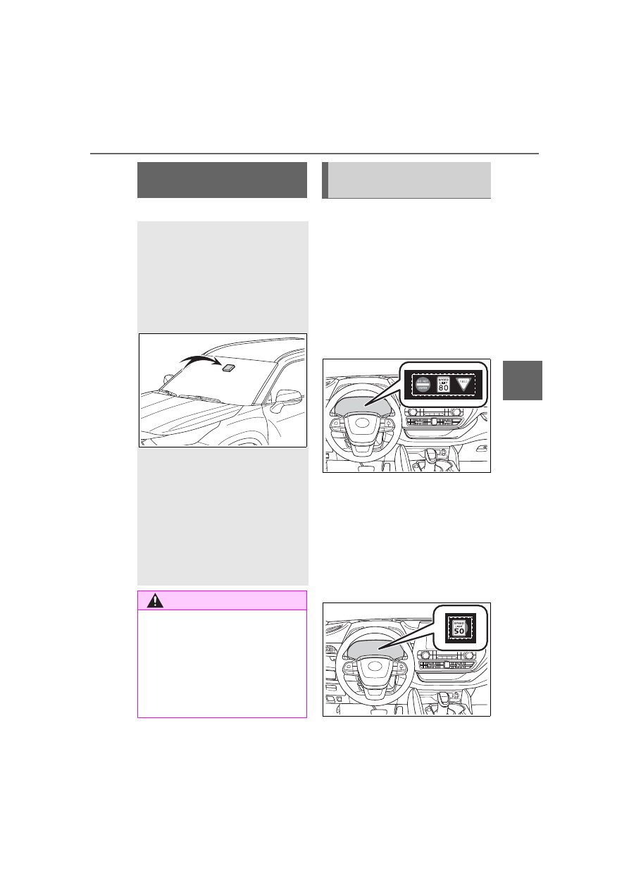
When the front camera recog-
nizes a sign and/or information 
of a sign is available from the 
navigation system, the sign will 
be displayed on the multi-infor-
mation display.

When the driving support sys-
tem information is selected, a 
maximum of 3 signs can be 
displayed. (

P.84, 93)

When a tab other than the 
driving support system infor-
mation is selected, the follow-
ing types of road signs will be 
displayed. (

P.84, 93)

• Speed limit sign
• Do Not Enter sign (when notifica-

tion is necessary)

If signs other than speed limit signs 

RSA (Road Sign 

Assist)

*

The RSA system recognizes 
specific road signs using 
the front camera and/or nav-
igation system (when speed 
limit information is avail-
able) to provide information 
to the driver via the display.

If the system judges that the 
vehicle is being driven over 
the speed limit, performing 
prohibited actions, etc. 
according to the recog-
nized road signs, it notifies 
the driver through a visual 
notification and notification 
buzzer.

WARNING

Before using the RSA

Do not rely solely upon the RSA 

system. RSA is a system which 

supports the driver by providing 

information, but it is not a replace-

ment for a driver’s own vision and 

awareness. Drive safely by 

always paying careful attention to 

the traffic rules.

Indication on the 
multi-information display

-------------------------------------------------------------------------------------------------------------------------------------------------------------

270

4-5. Using the driving support systems

HIGHLANDER_U

are recognized, they will be dis-
played in an overlapping stack 
under the current speed limit sign.

The following types of road 
signs, including electronic signs 
and blinking signs, are recog-
nized.

A non-official or a recently intro-
duced traffic sign may not be recog-
nized.

In the following situations, the 
RSA system will notify the 
driver.

When the vehicle speed 
exceeds the speed notifica-
tion threshold of the speed 
limit sign displayed, the sign 
display will be emphasized 
and a buzzer will sound.

When the RSA system recog-
nizes a do not enter sign and 

determines that your vehicle 
has entered a no-entry area, 
the displayed sign will flash 
and a buzzer will sound.

Depending on the situation, a 
notification function may not 
operate properly.

Setting procedure

4.2-inch display

1

Press 

 or 

 of the meter 

control switches and select 

.

2

Press 

 or 

 of the meter 

control switches and select 

then press 

.

7-inch display

1

Press 

 or 

 of the meter 

control switches and select 

.

2

Press 

 or 

 of the meter 

control switches and select 

then press 

.

Automatic turn-off of RSA sign 

display

In the following situations, a dis-

played speed limit sign and/or do 

not enter sign will stop being dis-

played automatically:

No sign has been recognized for a 

certain distance.

The road changes due to a left or 

right turn, etc.

In the following situations, stop and 

yield signs will stop being displayed 

automatically:

The system determines that your 

vehicle has passed the sign.

The road changes due to a left or 

right turn, etc.

Supported types of road 
signs

Speed limit

Do Not Enter

Stop

Yield

Notification function

-------------------------------------------------------------------------------------------------------------------------------------------------------------

271

4-5. Using the driving support systems

4

Dr

iv

ing

HIGHLANDER_U

Conditions in which the func-

tion may not operate or detect 

correctly

In the following situations, RSA 

does not operate normally and may 

not recognize signs, display the 

incorrect sign, etc. However, this 

does not indicate a malfunction.

The front camera is misaligned 

due to a strong impact being 

applied to the sensor, etc.

Dirt, snow, stickers, etc. are on the 

windshield near the front camera.

In inclement weather such as 

heavy rain, fog, snow or sand 

storms.

Light from an oncoming vehicle, 

the sun, etc. enters the front cam-

era.

The sign is dirty, faded, tilted or 

bent.

The contrast of electronic sign is 

low.

All or part of the sign is hidden by 

the leaves of a tree, a pole, etc.

The sign is only visible to the front 

camera for a short amount of time.

The driving scene (turning, lane 

change, etc.) is judged incorrectly.

If a sign not appropriate for the 

currently traveled lane, but the 

sign exists directly after a freeway 

branches, or in an adjacent lane 

just before merging.

Stickers are attached to the rear of 

the preceding vehicle.

A sign resembling a system com-

patible sign is recognized.

Side road speed signs may be 

detected and displayed (if posi-

tioned in sight of the front camera) 

while the vehicle is traveling on 

the main road.

Roundabout exit road speed signs 

may be detected and displayed (if 

positioned in sight of the front 

camera) while traveling on a 

roundabout.

The front of the vehicle is raised or 

lowered due to the carried load.

The surrounding brightness is not 

sufficient or changes suddenly.

When a sign intended for trucks, 

etc. is recognized.

The navigation system map data 

is outdated.

The navigation system is not oper-

ating.

The speed information displayed 

on the meter and on the naviga-

tion system may be different due 

to the navigation system using 

map data.

Speed limit sign display

If the engine switch was last turned 

off while a speed limit sign was dis-

played on the multi-information dis-

play, the same sign displays again 

when the engine switch is turned to 

ON.

If “RSA Malfunction Visit Your 

Dealer” is shown

The system may be malfunctioning. 

Have the vehicle inspected by your 

Toyota dealer.

Customization

Some functions can be customized. 

(Customizable features:

P.521)

-------------------------------------------------------------------------------------------------------------------------------------------------------------

272

4-5. Using the driving support systems

HIGHLANDER_U

*

: If equipped

Stopping the engine

While driving with the D shift 
position selected, depress the 
brake pedal and stop the vehi-
cle. The engine will stop auto-
matically.

When the engine stops, the Stop & 
Start indicator will illuminate.

Restarting the engine

Release the brake pedal. The 
engine will start automatically.

When the engine starts, the Stop & 
Start indicator will turn off.

When the brake hold sys-
tem is operating

When the engine is stopped 
by the Stop & Start system, if 
the brake pedal is released 
the engine will remain 
stopped.

If the accelerator pedal is 
depressed while the engine is 
stopped by the Stop & Start 
system, the engine will 
restart.

While the engine is stopped 
by the Stop & Start system, if 
the engine is restarted, the 
brake hold system will con-
tinue to apply the brakes, 
unless the operation condi-
tions of the brake hold system 
are no longer met. (

P.214)

When the dynamic radar 
cruise control with 
full-speed range is operat-
ing

When the vehicle is stopped 
by the dynamic radar cruise 
control with full-speed range, 
the engine will stop automati-
cally even though the brake 
pedal is not depressed.

When the preceding vehicle 
starts off, the engine will 
restart automatically.

If the engine is restarted by 
the Stop & Start system while 
the vehicle is stopped by the 
dynamic radar cruise control 
with full-speed range, the 

Stop & Start system

*

The Stop & Start system 
stops and starts the engine 
according to brake pedal or 
shift lever operation when 
the vehicle is stopped, such 
as at a stoplight, intersec-
tion, etc., in order to 
improve fuel economy and 
reduce noise pollution 
caused by the engine idling.

Stop & Start system oper-
ation

-------------------------------------------------------------------------------------------------------------------------------------------------------------

273

4-5. Using the driving support systems

4

Dr

iv

ing

HIGHLANDER_U

vehicle will remain stopped.

Press the Stop & Start cancel 
switch to disable the Stop & 
Start system.

The Stop & Start cancel indicator 
will illuminate.
Pressing the switch again will 
enable the Stop & Start system and 
the Stop & Start cancel indicator will 
turn off.

Automatic enabling of the Stop 

& Start system

If the Stop & Start system is dis-

abled using the Stop & Start cancel 

switch, it will be automatically 

re-enabled once the engine switch 

is turned off and then the engine is 

started.

When the engine is stopped by 
the Stop & Start system when 
the vehicle is on an incline, 
when the brake pedal is 
released, brake force is tempo-
rarily maintained to prevent the 
vehicle from rolling backwards 
before the engine is restarted 

and drive force is generated. 
When drive force is generated, 
the maintained brake force is 
automatically canceled.

This function operates on flat 
surfaces as well as steep 
inclines.

Sound may be generated 
from the brake system, but 
this does not indicate a mal-
function.

Brake pedal response may 
change and vibration may 
occur, but this does not indi-
cate a malfunction.

Points for use

If the engine switch is pressed 

when the engine is stopped by the 

Stop & Start system, the engine 

will not be able to be restarted by 

the automatic engine start func-

tion. In this case, restart the 

engine using the normal engine 

starting procedure. (

P.202)

When the engine is being 

restarted by the Stop & Start sys-

tem, the power outlets may be 

temporarily unusable, but this 

does not indicate a malfunction.

Installation and removal of electri-

cal components and wireless 

devices may affect the Stop & 

Start system. Contact your Toyota 

dealer for details.

When stopping the vehicle for a 

longer period of time, turn the 

engine switch off to stop the 

engine completely.

When the engine is restarted by 

the Stop & Start system, the steer-

ing wheel may temporarily feel 

heavy.

Disabling the Stop & Start 
system

Hill-start assist control

-------------------------------------------------------------------------------------------------------------------------------------------------------------

274

4-5. Using the driving support systems

HIGHLANDER_U

Operating conditions

The Stop & Start system is opera-

tional when all of the following 

conditions are met:

• The vehicle has been driven a cer-

tain amount of time.

• The brake pedal is being 

depressed firmly. (Except when 

the vehicle is stopped by the 

dynamic radar cruise control with 

full-speed range when in vehi-

cle-to-vehicle distance control 

mode)

• The D shift position is selected.

• The driver’s seat belt is fastened.

• The driver’s door is closed.

• The selected driving mode is 

NORMAL or ECO mode.

• The selected driving mode is not 

SNOW mode.

• The windshield defogger is off. 

(vehicles without a manual air 

conditioning system)

• The accelerator pedal is not being 

depressed.

• The engine is adequately warmed 

up.

• The outside temperature is 23°F 

(-5°C ) or higher.

• The hood is closed. (

P.275)

In the following situations the 

engine may not be stopped by the 

Stop & Start system. This is not a 

malfunction of the Stop & Start 

system.

• When the air conditioning system 

is being used.

• When the battery is undergoing a 

periodic recharge.

• When the battery is not sufficiently 

charged, such as if the vehicle 

has been parked for a long time 

and the battery charge has 

decreased, the electric load is 

large, the battery fluid tempera-

ture is excessively low or the bat-

tery has deteriorated.

• When the brake booster vacuum 

is low.

• When the elapsed time since the 

engine was restarted is short.

• When the vehicle is stopped fre-

quently, such as when in a traffic 

jam.

• When the engine coolant tem-

perature or transmission fluid tem-

perature is extremely low or high.

• When the vehicle is stopped on a 

steep incline.

• When the steering wheel is being 

operated.

• When the vehicle is being driven 

in a high altitude area.

• When the battery fluid tempera-

ture is extremely low or high.

• For a while after the battery termi-

nals have been disconnected and 

reconnected.

When the engine is stopped by 

the Stop & Start system, the 

engine will be restarted automati-

cally if any of the following condi-

tions are met: (To enable the 

engine to be stopped by the Stop 

& Start system again, drive the 

vehicle.)

• The air conditioning system is 

turned on. (vehicles without a 

manual air conditioning system)

• The windshield defogger is turned 

on. (vehicles without a manual air 

conditioning system)

• The shift lever is shifted from D or 

P.

• The shift lever is shifted from P. 

(When the engine is stopped by 

the Stop & Start system when the 

shift lever is in P.)

• The driver’s seat belt is unfas-

tened.

• The driver’s door is opened.

• The driving mode is changed from 

NORMAL or ECO mode to 

another mode.

• The driving mode is changed to 

SNOW mode.

• The Stop & Start cancel switch is 

pressed.

• The steering wheel is operated.

• The accelerator pedal is 

depressed.

• The vehicle starts to roll on an 

incline.

When the engine is stopped by 

the Stop & Start system, the 

engine may restart automatically 

-------------------------------------------------------------------------------------------------------------------------------------------------------------

275

4-5. Using the driving support systems

4

Dr

iv

ing

HIGHLANDER_U

in the following situations: (To 

enable the engine to be stopped 

by the Stop & Start system again, 

drive the vehicle.)

• When the brake pedal is pumped 

or strongly depressed.

• When the air conditioning system 

is being used.

• When a switch of the air condition-

ing system is operated (windshield 

defogger switch, etc.).

• If the battery charge becomes low.

When the hood is opened

If the hood is opened while the 

engine is stopped by the Stop & 

Start system, the engine will stall 

and will not be able to be restarted 

by the automatic engine start 

function. In this case, restart the 

engine using the normal engine 

starting procedure. (

P.202)

If the hood is closed after the 

engine is started with the hood 

open, the Stop & Start system will 

not operate. Close the hood, turn 

the engine switch off, wait 30 sec-

onds or more, and then start the 

engine.

Air conditioning system opera-

tion while the engine is stopped 

by the Stop & Start system

Vehicles with an automatic air con-

ditioning system: When the air con-

ditioning is in automatic mode and 

the engine is stopped by the Stop & 

Start system, the fan may operate at 

a low speed in order to prevent the 

temperature in the cabin from 

increasing or decreasing or may be 

stopped.
To prioritize air conditioning system 

performance when the vehicle is 

stopped, disable the Stop & Start 

system by pressing the Stop & Start 

cancel switch.

If the windshield is fogged up

Turn the windshield defogger on. 
(

P.341)

If the windshield fogs up frequently, 
press the Stop & Start cancel switch 

to disable the Stop & Start system.

If an odor is emitted from the air 

conditioning system

• Vehicles with a manual air condi-

tioning system

If the idling stop time setting is set to 
“Extended” change it to “Standard”. 
If an odor is emitted when the idling 
stop time setting is set to “Stan-
dard”, press the Stop & Start cancel 
switch to deactivate the Stop & Start 
system.
• Vehicles with an automatic air 

conditioning system

Press the Stop & Start cancel switch 
to deactivate the Stop & Start sys-
tem.

Changing the idling stop time 

with the air conditioning system 

on

The length of time the Stop & Start 

system will operate when the air 

conditioning system is on can be 
changed in 

 of the multi-informa-

tion display (

P.89, 98). (The length 

of time the Stop & Start system will 

operate when the air conditioning 

system is off cannot be changed.)

Displaying the Stop & Start sys-

tem status

P.89, 98

Multi-information display mes-

sages

If the following situations, 

 and a 

message may be displayed on the 

multi-information display.

When the engine cannot be 

stopped by the Stop & Start sys-

tem

 “Press brake more to activate”

• The brake pedal is not sufficiently 

depressed.

 If the brake pedal is depressed 

further, the system will operate.

-------------------------------------------------------------------------------------------------------------------------------------------------------------

276

4-5. Using the driving support systems

HIGHLANDER_U

 “Non-Dedicated Battery”

• A battery not designed for use 

with a Stop & Start system may 

have been installed.

 Have the vehicle inspected by 

your Toyota dealer.

 “Battery Charging”

• The battery charge may be low.

 Stopping of the engine is tempo-

rarily prohibited to prioritize charging 
of the battery. After the engine runs 
for a certain amount of time, the sys-
tem will be enabled.
• A refresh charge may be occur-

ring

 After a refresh charge for up to 

an hour completes, the system can 
be operated.
• If displayed continuously for a 

long time (more than an hour)

 The battery may be deteriorated. 

Contact your Toyota dealer for 
details.

 “Stop & Start System Unavail-

able”
• The Stop & Start system is tempo-

rarily disabled.

 Allow the engine to run for some 

time.
• The engine may have been 

started with the hood open.

 Close the hood, turn the engine 

switch off, wait for 30 seconds or 
more, and then start the engine.

 “In Preparation”

• The vehicle is being driven in a 

high altitude area.

• The brake booster vacuum is low.

 When the brake booster vacuum 

reaches a predetermined level, the 
system will be enabled.

 “For Climate Control”

• The air conditioning system is 

being used when the ambient 

temperature is high or low.

 If the difference between the set 

temperature and cabin temperature 
becomes small, the system will be 
enabled.
• The windshield defogger is on.

When the engine automatically 

restarts while stopped by the Stop 

& Start system

 “In Preparation”

• The brake pedal has been 

depressed further or pumped.

 The system will be enabled after 

the engine runs and the brake 
booster vacuum reaches a predeter-
mined level.

 “For Climate Control”

• The air conditioning system has 

been turned on or is being used.

• The windshield defogger has 

been turned on.

 “Battery Charging”

• The battery charge may be low.

 The system will be enabled after 

the engine runs to sufficiently 
charge the battery.

When the buzzer sounds

If the driver’s door is opened when 

the engine is stopped by the Stop & 

Start system and the shift lever is in 

D, a buzzer will sound and the Stop 

& Start system indicator will flash. To 

stop the buzzer, close the driver’s 

door.

The Stop & Start system protec-

tion function

When the volume of the audio 

system is excessively high, sound 

output from the audio system may 

suddenly be cut off in order to 

-------------------------------------------------------------------------------------------------------------------------------------------------------------

277

4-5. Using the driving support systems

4

Dr

iv

ing

HIGHLANDER_U

reduce battery consumption. To 

prevent the audio system from 

being cut off, keep the volume of 

audio system at a moderate level. 

If the audio system has been cut 

off, turn the engine switch off, wait 

for 3 seconds or more and then 

turn it to ACC or ON to re-enable 

the audio system.

The audio system may not be acti-

vated if the battery terminals are 

disconnected and then recon-

nected. If this occurs, turn the 

engine switch off and then repeat 

the following operation twice to 

activate the audio system nor-

mally.

• Turn the engine switch to ON and 

then to OFF.

Replacing the battery

P.493

If the Stop & Start cancel indica-

tor flashes continuously

The system may be malfunctioning. 

Have the vehicle inspected by your 

Toyota dealer.

If “Stop & Start System Mal-

function Visit Your Dealer” is 

displayed on the multi-informa-

tion display

The system may be malfunctioning. 

Have the vehicle inspected by your 

Toyota dealer.

WARNING

When the Stop & Start system 

is operating

Make sure to disable the Stop & 

Start system while the vehicle is in 

a poorly ventilated area. If not dis-

abled, the engine may be auto-

matically restarted unexpectedly, 

causing exhaust gases to collect 

and enter the vehicle, possibly 

resulting in death or a serious 

health hazard.

Do not leave the vehicle while 

the engine is stopped by the 

Stop & Start system (while the 

Stop & Start indicator is on). An 

accident may occur due to the 

automatic engine start function.

Depress the brake pedal and 

apply the parking brake when 

necessary while the engine is 

stopped by the Stop & Start sys-

tem (while the Stop & Start indi-

cator is on).

NOTICE

To ensure the system oper-

ates correctly

If any of the following situations 

occur, the Stop & Start system 

may not operate correctly. Have 

your vehicle inspected by your 

Toyota dealer.

While the driver’s seat belt is 

fastened, the driver’s and front 

passenger’s seat belt reminder 

light flashes.

Even though the driver’s seat 

belt is not fastened, the driver’s 

and front passenger’s seat belt 

reminder light does not illumi-

nate.

Even though the driver’s door is 

closed, the open door warning 

light is illuminated or the interior 

light is illuminated when the 

interior light switch is in the door 

position.

Even though the driver’s door is 

open, the open door warning 

light does not illuminate or the 

interior light does not illuminate 

when the interior light switch is 

in the door position.

-------------------------------------------------------------------------------------------------------------------------------------------------------------

278

4-5. Using the driving support systems

HIGHLANDER_U

*

: If equipped

Meter control switches

Turning the Blind Spot Monitor 
on/off.
When the BSM function is disabled, 
the BSM OFF indicator illuminates.

Outside rear view mirror indi-
cators

When a vehicle is detected in a 
blind spot of the outside rear view 
mirrors or approaching rapidly from 
behind into a blind spot, the outside 
rear view mirror indicator on the 
detected side will illuminate. If the 
turn signal lever is operated toward 
the detected side, the outside rear 
view mirror indicator flashes.

Outside rear view mirror indica-

tor visibility

In strong sunlight, the outside rear 

view mirror indicator may be difficult 

to see.

When “Blind Spot Monitor 

Unavailable” is shown on the 

multi-information display

Ice, snow, mud, etc., may be 

attached to the rear bumper around 

the sensors. (

P.280) The system 

should return to normal operation 

after removing the ice, snow, mud, 

etc. from the rear bumper. Addition-

ally, the sensors may not operate 

normally when driving in extremely 

BSM (Blind Spot Moni-

tor)

*

The Blind Spot Monitor is a 
system that uses rear side 
radar sensors installed on 
the inner side of the rear 
bumper on the left and right 
side to assist the driver in 
confirming safety when 
changing lanes.

WARNING

Cautions regarding the use of 

the system

The driver is solely responsible for 

safe driving. Always drive safely, 

taking care to observe your sur-

roundings.
The Blind Spot Monitor is a sup-

plementary function which alerts 

the driver that a vehicle is in a 

blind spot of the outside rear view 

mirrors or is approaching rapidly 

from behind into a blind spot. Do 

not overly rely on the Blind Spot 

Monitor. As the function cannot 

judge if it is safe to change lanes, 

over reliance could lead to an 

accident resulting in death or seri-

ous injury.
As the system may not function 

correctly under certain condi-

tions, the driver’s own visual con-

firmation of safety is necessary.

System components

-------------------------------------------------------------------------------------------------------------------------------------------------------------

279

4-5. Using the driving support systems

4

Dr

iv

ing

HIGHLANDER_U

hot or cold environments.

When “Blind Spot Monitor Mal-

function Visit Your Dealer” is 

shown on the multi-information 

display

There may be a sensor malfunction 

of misaligned. Have the vehicle 

inspected by your Toyota dealer.

Customization

Some functions can be customized. 

(

P.521)

Certification

For vehicles sold in the U.S.A.

For vehicles sold in Canada

-------------------------------------------------------------------------------------------------------------------------------------------------------------

280

4-5. Using the driving support systems

HIGHLANDER_U

WARNING

Handling the rear side radar 

sensor

Blind Spot Monitor sensors are 

installed behind the left and right 

sides of the rear bumper respec-

tively. Observe the following to 

ensure the Blind Spot Monitor can 

operate correctly.

Keep the sensors and the sur-

rounding areas on the rear 

bumper clean at all times.

If a sensor or its surrounding area 
on the rear bumper is dirty or cov-
ered with snow, the Blind Spot 
Monitor may not operate and a 
warning message (

P.278) will 

be displayed. In this situation, 
clear off the dirt or snow and drive 
the vehicle with the operation con-
ditions of the BSM function 
(

P.282) satisfied for approxi-

mately 10 minutes. If the warning 
message does not disappear, 
have the vehicle inspected by 
your Toyota dealer.

Do not attach stickers to the 

sensor or surrounding area on 

the rear bumper.

-------------------------------------------------------------------------------------------------------------------------------------------------------------

281

4-5. Using the driving support systems

4

Dr

iv

ing

HIGHLANDER_U

Use the meter control switches 
to turn on/off the function.

4.2-inch display

1

Press 

 or 

 of the meter 

control switches and select 

.

2

Press 

 or 

 of the meter 

control switches to select 


and then press 

.

7-inch display

1

Press 

 or 

 of the meter 

control switches and select 

.

2

Press 

 or 

 of the meter 

control switches to select 


and then press 

.

Vehicles that can be detected by the Blind Spot Monitor

The Blind Spot Monitor uses rear side radar sensors to detect the fol-
lowing vehicles traveling in adjacent lanes and advises the driver of 
the presence of such vehicles via the indicators on the outside rear 
view mirrors.

WARNING

Do not subject a sensor or its 

surrounding area on the rear 

bumper to a strong impact.

If a sensor is moved even 

slightly off position, the system 

may malfunction and vehicles 

may not be detected correctly.

In the following situations, have 

your vehicle inspected by your 

Toyota dealer.

• A sensor or its surrounding area 

is subject to a strong impact.

• If the surrounding area of a sen-

sor is scratched or dented, or 

part of them has become dis-

connected.

Do not disassemble the sensor.

Do not modify the sensor or sur-

rounding area on the rear 

bumper.

If a sensor or the rear bumper 

needs to be removed/installed 

or replaced, contact your Toyota 

dealer.

Do not paint the rear bumper 

any color other than an official 

Toyota color.

Turning the Blind Spot 
Monitor on/off

Blind Spot Monitor operation

-------------------------------------------------------------------------------------------------------------------------------------------------------------

282

4-5. Using the driving support systems

HIGHLANDER_U

Vehicles that are traveling in areas that are not visible using the 
outside rear view mirrors (the blind spots)
Vehicles that are approaching rapidly from behind in areas that 
are not visible using the outside rear view mirrors (the blind spots)

The Blind Spot Monitor detection areas

The areas that vehicles can be detected in are outlined below.

The range of each detection area is:

Approximately 1.6 ft. (0.5 m) to 11.5 ft. (3.5 m) from either side of 
the vehicle

*1

Approximately 3.3 ft. (1 m) forward of the rear bumper
Approximately 9.8 ft. (3 m) from the rear bumper
Approximately 9.8 ft. (3 m) to 197 ft. (60 m) from the rear 
bumper

*2

*1

:The area between the side of the vehicle and 1.6 ft. (0.5 m) from the side 

of the vehicle cannot be detected.

*2

:The greater the difference in speed between your vehicle and the 

detected vehicle is, the farther away the vehicle will be detected, causing 
the outside rear view mirror indicator to illuminate or flash.

The Blind Spot Monitor is oper-

ational when

The Blind Spot Monitor is opera-

-------------------------------------------------------------------------------------------------------------------------------------------------------------

283

4-5. Using the driving support systems

4

Dr

iv

ing

HIGHLANDER_U

tional when all of the following con-

ditions are met:

The Blind Spot Monitor is on.

The shift lever is in a position 

other than R.

The vehicle speed is greater than 

approximately 10 mph (16 km/h).

The Blind Spot Monitor will 

detect a vehicle when

The Blind Spot Monitor will detect a 

vehicle present in the detection area 

in the following situations:

A vehicle in an adjacent lane over-

takes your vehicle.

You overtake a vehicle in an adja-

cent lane slowly.

Another vehicle enters the detec-

tion area when it changes lanes.

Conditions under which the 

Blind Spot Monitor will not 

detect a vehicle

The Blind Spot Monitor is not 

designed to detect the following 

types of vehicles and/or objects:

Small motorcycles, bicycles, 
pedestrians, etc.

*

Vehicles traveling in the opposite 

direction

Guardrails, walls, signs, parked 

vehicles and similar stationary 
objects

*

Following vehicles that are in the 
same lane

*

Vehicles traveling 2 lanes away 
from your vehicle

*

Vehicles which are being over-
taken rapidly by your vehicle

*

*

: Depending on the conditions, 

detection of a vehicle and/or 
object may occur.

Conditions under which the 

Blind Spot Monitor may not 

function correctly

The Blind Spot Monitor may not 

detect vehicles correctly in the fol-

lowing situations:

• When the sensor is misaligned 

due to a strong impact to the sen-

sor or its surrounding area

• When mud, snow, ice, a sticker, 

etc. is covering the sensor or sur-

rounding area on the rear bumper

• When driving on a road surface 

that is wet with standing water 

during bad weather, such as 

heavy rain, snow, or fog

• When multiple vehicles are 

approaching with only a small gap 

between each vehicle

• When the distance between your 

vehicle and a following vehicle is 

short

• When there is a significant differ-

ence in speed between your vehi-

cle and the vehicle that enters the 

detection area

• When the difference in speed 

between your vehicle and another 

vehicle is changing

• When a vehicle enters a detection 

area traveling at about the same 

speed as your vehicle

• As your vehicle starts from a stop, 

a vehicle remains in the detection 

area

• When driving up and down con-

secutive steep inclines, such as 

hills, dips in the road, etc.

• When driving on roads with sharp 

bends, consecutive curves, or 

uneven surfaces

• When vehicle lanes are wide, or 

when driving on the edge of a 

lane, and the vehicle in an adja-

cent lane is far away from your 

vehicle

• When towing a trailer

• When an accessory (such as a 

bicycle carrier) is installed to the 

rear of the vehicle

• When there is a significant differ-

ence in height between your vehi-

cle and the vehicle that enters the 

detection area

• Immediately after the Blind Spot 

Monitor is turned on

Instances of the Blind Spot Moni-

tor unnecessarily detecting a vehi-

-------------------------------------------------------------------------------------------------------------------------------------------------------------

284

4-5. Using the driving support systems

HIGHLANDER_U

cle and/or object may increase in 

the following situations:

• When the sensor is misaligned 

due to a strong impact to the sen-

sor or its surrounding area

• When the distance between your 

vehicle and a guardrail, wall, etc. 

that enters the detection area is 

short

• When driving up and down con-

secutive steep inclines, such as 

hills, dips in the road, etc.

• When vehicle lanes are narrow, or 

when driving on the edge of a 

lane, and a vehicle traveling in a 

lane other than the adjacent lanes 

enters the detection area

• When driving on roads with sharp 

bends, consecutive curves, or 

uneven surfaces

• When the tires are slipping or 

spinning

• When the distance between your 

vehicle and a following vehicle is 

short

• When an accessory (such as a 

bicycle carrier) is installed to the 

rear of the vehicle

*

: If equipped

Types of sensors

Front corner sensors
Front center sensors
Rear corner sensors
Rear center sensors

Display

When the sensors detect an 
object, such as a wall, a graphic 
is shown on the multi-informa-
tion display, head-up display (if 

Intuitive parking 

assist

*

The distance from your 
vehicle to objects, such as a 
wall, when parallel parking 
or maneuvering into a 
garage is measured by the 
sensors and communicated 
via the multi-information 
display, head-up display (if 
equipped), audio system 
screen and a buzzer. Always 
check the surrounding area 
when using this system.

System components

-------------------------------------------------------------------------------------------------------------------------------------------------------------

285

4-5. Using the driving support systems

4

Dr

iv

ing

HIGHLANDER_U

equipped) and audio system 
screen depending on the posi-
tion and distance to the object.

Multi-information display and 
head-up display

Front corner sensor detection
Front center sensor detection
Rear corner sensor detection
Rear center sensor detection

Audio system screen (vehi-
cles with a Toyota parking 
assist monitor)

When the R shift lever is selected, 
a simplified image is displayed on 
the audio system screen.

Audio system screen (vehi-
cles with a Panoramic view 
monitor)

A graphic will be displayed on the 
audio system screen.

Use the meter control switches 
to enable/disable the intuitive 
parking assist. (

P.98)

1

Press 

 or 

 to select 

.

2

Press 

 or 

 to select 


and then press 

.

When the intuitive parking assist 
function is disabled, the intuitive 
parking assist OFF indicator 
(

P.78) illuminates.

To re-enable the system, select 

 on the multi-information dis-

play, select 

 and turn it on. If 

the system is disabled, it will 
remain off even if the engine 
switch is turned to ON after the 
engine switch has been turned 
off.

Turning intuitive parking 
assist on/off

-------------------------------------------------------------------------------------------------------------------------------------------------------------

286

4-5. Using the driving support systems

HIGHLANDER_U

WARNING

When using the intuitive park-

ing assist

Observe the following precau-

tions. 

Failing to do so may result in the 

vehicle being unable to be driven 

safely and possibly cause an acci-

dent.

Do not use the sensor at 

speeds in excess of 6 mph (10 

km/h).

The sensors’ detection areas 

and reaction times are limited. 

When moving forward or revers-

ing, check the areas surround-

ing the vehicle (especially the 

sides of the vehicle) for safety, 

and drive slowly, using the 

brake to control the vehicle’s 

speed.

Do not install accessories within 

the sensors’ detection areas.

The area directly under the 

bumpers is not detected.

Thin posts or objects lower than 

the sensor may not be detected 

when approached, even if they 

have been detected once.

When to disable the function

In the following situations, disable 

the function as it may operate 

even though there is no possibility 

of a collision.

The vehicle is equipped with a 

fender pole, wireless antenna or 

fog lights.

The front or rear bumper or a 

sensor receives a strong 

impact.

A non-genuine Toyota suspen-

sion (lowered suspension, etc.) 

is installed.

Towing eyelets are installed.

A backlit licence plate is 

installed.

When using intuitive parking 

assist

In the following situations, the 

system may not function correctly 

due to a sensor malfunction, etc. 

Have the vehicle checked by your 

Toyota dealer.

The intuitive parking assist 

operation display flashes or 

shows continuously, and a 

buzzer sounds when no objects 

are detected.

If the area around a sensor col-

lides with something, or is sub-

jected to strong impact.

If the bumper or grille collides 

with something.

If the display flashes or is dis-

played continuously and a 

buzzer does not sound, except 

when the mute function has 

been turned on.

If a display error occurs, first 

check the sensor. 

If the error occurs even when 

there is no ice, snow or mud on 

the sensor, it is likely that the 

sensor is malfunctioning.

Notes when washing the vehi-

cle

Do not apply intensive bursts of 

water or steam to the sensor 

area.
Doing so may result in the sensor 

malfunctioning.

When using a high pressure 

washer to wash the vehicle, do 

not spray the sensors directly, 

as doing so may cause a sensor 

to malfunction.

-------------------------------------------------------------------------------------------------------------------------------------------------------------

287

4-5. Using the driving support systems

4

Dr

iv

ing

HIGHLANDER_U

The system can be operated 

when

The engine switch is in ON.

Intuitive parking assist function is 

on.

The vehicle speed is less than 

about 6 mph (10 km/h).

A shift lever other than P.

If “Parking Assist Unavailable” 

is displayed on the multi-infor-

mation display

Water may be continuously flow-

ing over the sensor surface, such 

as in a heavy rain. When the sys-

tem determines that it is normal, 

the system will return to normal.

Initialization may not have been 

performed after a battery terminal 

was disconnected and recon-

nected. Initialize the system. 

(

P.287) If this message contin-

ues to be displayed even after ini-

tialization, have the vehicle 

inspected by your Toyota dealer.

If “Parking Assist Unavailable 

Clean Parking Assist Sensor” is 

displayed on the multi-informa-

tion display

A sensor may be covered with ice, 

snow, dirt, etc. Remove the ice, 

snow, dirt, etc., from the sensor to 

return the system to normal.
Also, due to ice forming on a sensor 

at low temperatures, a warning 

message may be displayed or the 

sensor may not be able to detect an 

object. Once the ice melts, the sys-

tem will return to normal.

If a battery terminal has been 

disconnected and reconnected

The system needs to be initialized. 

To initialize the system, drive the 

vehicle straight ahead for 5 seconds 

or more at a speed of approximately 

22 mph (35 km/h) or more.

Sensor detection information

The following situations may occur 

during use.

• The sensor's detection areas are 

limited to the areas around the 

vehicle front and rear bumpers.

• Depending on the shape of the 

object and other factors, the 

detection distance may shorten, or 

detection may be impossible.

• If an object is extremely close to a 

sensor, it may not be detected.

• There will be a short delay 

between object detection and dis-

play. Even at low speeds, there is 

a possibility that the object will 

come within the sensor’s detec-

tion areas before the display is 

shown and the warning beep 

sounds.

• It might be difficult to hear the 

buzzer due to the volume of the 

audio system or air flow noise of 

the air conditioning system.

• It may be difficult to hear the 

buzzer if buzzers for other sys-

tems are sounding.

Conditions under which the 

function may not function cor-

rectly

Certain vehicle conditions and the 

surrounding environment may affect 

the ability of a sensor to correctly 

detect objects. Particular instances 

where this may occur are listed 

below.

There is dirt, snow or ice on a sen-

sor. (Cleaning the sensors will 

resolve this problem.)

A sensor is frozen. (Thawing the 

area will resolve this problem.) 

In especially cold weather, if a 

sensor is frozen the sensor dis-

play may be displayed abnormally, 

WARNING

When using steam to clean the 

vehicle, do not direct steam too 

close to the sensors as doing so 

may cause a sensor to malfunc-

tion.

-------------------------------------------------------------------------------------------------------------------------------------------------------------

288

4-5. Using the driving support systems

HIGHLANDER_U

or objects, such as a wall, may not 

be detected.

A sensor is covered in any way.

When a sensor or the area around 

a sensor is extremely hot or cold.

On an extremely bumpy road, on 

an incline, on gravel, or on grass.

The vicinity of the vehicle is noisy 

due to vehicle horns, motorcycle 

engines, air brakes of large vehi-

cles, or other loud noises produc-

ing ultrasonic waves.

There is another vehicle equipped 

with parking assist sensors in the 

vicinity.

A sensor is coated with a sheet of 

spray or heavy rain.

If a sensor is hit by a large amount 

of water, such as when driving on 

a flooded road.

If the vehicle is significantly tilted.

The vehicle is approaching a tall 

or curved curb.

If objects draw too close to the 

sensor.

Objects which may not be prop-

erly detected

The shape of the object may pre-

vent the sensor from detecting it. 

Pay particular attention to the follow-

ing objects:

Wires, fences, ropes, etc.

Cotton, snow and other materials 

that absorb sound waves

Sharply-angled objects

Low objects

Tall objects with upper sections 

projecting outwards in the direc-

tion of your vehicle

People may not be detected if they 

are wearing certain types of cloth-

ing.

Adjusting the buzzer vol-
ume

The buzzer volume can be 
adjusted on the multi-informa-
tion display.
Use the meter control switches 
to change settings. (

P.98)

1

Press 

 or 

 to select 

.

2

Press 

 or 

 to select and 

 then press and hold 

.

3

Select the volume and then 
press 

.

Each time the switch is pressed, 

the volume level will change 

between 1, 2, and 3.

Muting a buzzer temporarily

A mute button will be displayed 
on the multi-information display 
when an object is detected. To 
mute the buzzer, press 

.

Mute will be canceled automati-
cally in the following situations:

When the shift lever is 
changed.

When the vehicle speed 
exceeds a certain speed.

When there is malfunction in 
a sensor or the system is tem-
porarily unavailable.

When the operating function 
is disabled manually.

When the engine switch is 
turned off.

Setting the buzzer volume

-------------------------------------------------------------------------------------------------------------------------------------------------------------

289

4-5. Using the driving support systems

4

Dr

iv

ing

HIGHLANDER_U

Detection range of the sen-
sors

Approximately 3.3 ft. (100 
cm)
Approximately 4.9 ft. (150 
cm)
Approximately 2.0 ft. (60 cm)

The diagram shows the detection 
range of the sensors. Note that the 
sensors cannot detect objects that 
are extremely close to the vehicle.
The range of the sensors may 
change depending on the shape of 
the object, etc.

Multi-information display, head-up display (if equipped) and 
audio system screen

When an object is detected by a sensor, the approximate distance to 
the object will be displayed on the multi-information display, audio 
system screen, and head-up display (if equipped). (As the distance 
to the object becomes short, the distance segments may blink.)

Approximate distance to object: 4.9 ft. (150 cm) to 2.0 ft. (60 
cm)

*

(Rear center sensor)

*

: Automatic buzzer mute function is enabled. (

P.291)

Approximate distance to object: 3.3 ft. (100 cm) to 2.0 ft. (60 cm)

*


(Front center sensor)

Sensor detection display, 
object distance

Multi-information dis-

play

Audio system screen

Head-up display

-------------------------------------------------------------------------------------------------------------------------------------------------------------

290

4-5. Using the driving support systems

HIGHLANDER_U

*

: Automatic buzzer mute function is enabled. (

P.291)

Approximate distance to object: 2.0 ft. (60 cm) to 1.5 ft. (45 cm)

*

*

: Automatic buzzer mute function is enabled. (

P.291)

Approximate distance to object: 1.5 ft. (45 cm) to 1.0 ft. (30 cm)

*

*

: Automatic buzzer mute function is enabled. (

P.291)

Approximate distance to object: 1.0 ft. (30 cm) to 0.5 ft. (15 cm)

*1

*1

:Automatic buzzer mute function is disabled. (

P.291)

*2

:The distance segments will blink slowly.

Approximate distance to object: Less than 0.5 ft. (15 cm)

*1

Multi-information dis-

play

Audio system screen

Head-up display

Multi-information dis-

play

Audio system screen

Head-up display

Multi-information dis-

play

Audio system screen

Head-up display

Multi-information dis-

play

*2

Audio system screen

*2

Head-up display

-------------------------------------------------------------------------------------------------------------------------------------------------------------

291

4-5. Using the driving support systems

4

Dr

iv

ing

HIGHLANDER_U

*1

:Automatic buzzer mute function is disabled. (

P.291)

*2

:The distance segments will blink rapidly.

Buzzer operation and dis-
tance to an object

A buzzer sounds when the sen-
sors are operating.

The buzzer beeps faster as 
the vehicle approaches an 
object. When the vehicle 
comes within approximately 
1.0 ft. (30 cm) of the object, 
the buzzer sounds continu-
ously.

When 2 or more objects are 
detected simultaneously, the 
buzzer sounds for the nearest 
object. If one or more objects 
come within approximately 
1.0 ft. (30 cm) of the vehicle, 
the buzzer will repeat a long 
tone, followed by fast beeps.

Automatic buzzer mute func-
tion: After a buzzer begins 
sounding, if the distance 
between the vehicle and the 
detected object does not 
become shorter, the buzzer 
will be muted automatically. 
(However, if the distance 
between the vehicle and 
object is 1.0 ft. (30 cm) or 
less, this function will not 

operate.)

The buzzer sounds volume can 
be adjusted. (

P.288)

Multi-information dis-

play

*2

Audio system screen

*2

Head-up display

-------------------------------------------------------------------------------------------------------------------------------------------------------------

292

4-5. Using the driving support systems

HIGHLANDER_U

*

: If equipped

Meter control switches

Turning the RCTA function on/off.
When the RCTA function is dis-
abled, the RCTA OFF indicator illu-
minates.

Outside rear view mirror indi-
cators

When a vehicle approaching from 

the right or left at the rear of the 
vehicle is detected, both outside 
rear view mirror indicators will flash.

Audio system screen

If a vehicle approaching from the 
right or left at the rear of the vehicle 
is detected, the RCTA icon 
(

P.294) for the detected side will 

be displayed on the audio system 
screen. This illustration shows an 
example of a vehicle approaching 
from both sides of the vehicle.

RCTA buzzer

If a vehicle approaching from the 
right or left at the rear of the vehicle 
is detected, a buzzer will sound.

4.2-inch display

Use the meter control switches 
to enable/disable the RCTA 
function. (

P.89)

1

Press 

 or 

 to select 

.

2

Press 

 or 

 to select 

“RCTA” and then press 

.

7-inch display

Use the meter control switches 
to enable/disable the RCTA 
function. (

P.98)

1

Press 

 or 

 to select 

.

2

Press 

 or 

 to select 

“RCTA” and then press 

.

When the RCTA function is dis-
abled, the RCTA OFF indicator 
(

P.78) illuminates on the 

RCTA (Rear Cross Traf-

fic Alert) function

*

The RCTA function uses the 
BSM rear side radar sensors 
installed behind the rear 
bumper. This function is 
intended to assist the driver 
in checking areas that are 
not easily visible when 
backing up.

System components

Turning the RCTA func-
tion on/off

-------------------------------------------------------------------------------------------------------------------------------------------------------------

293

4-5. Using the driving support systems

4

Dr

iv

ing

HIGHLANDER_U

multi-information display. (Each 
time the engine switch is turned off 
then changed to ON, the RCTA 
function will be enabled automati-
cally.)

Outside rear view mirror indica-

tor visibility

In strong sunlight, the outside rear 

view mirror indicator may be difficult 

to see.

Hearing the RCTA buzzer

The RCTA buzzer may be difficult to 

hear over loud noises, such as if the 

audio system volume is high.

When “Rear Cross Traffic Alert 

Unavailable” is shown on the 

multi-information display

Water, ice, snow, mud, etc., may be 

attached to the rear bumper around 

the sensors. (

P.280) Removing 

the water, ice, snow, mud, etc., from 

the attached to the rear bumper 

around the sensors to return the 

function to normal.
Additionally, the function may not 

operate normally when driving in 

extremely hot or cold environments.

Rear side radar sensors

P.280

Adjusting the buzzer vol-
ume

The buzzer volume can be 
adjusted on the multi-informa-
tion display.

4.2-inch display

Use the meter control switches 
to change settings. (

P.89)

1

Press 

 or 

 to select 

.

2

Press 

 or 

 to select 

“RCTA” and then press and 
hold 

.

3

Select the volume and then 
press 

.

Each time the switch is pressed, 

the volume level will change 

between 1, 2, and 3.

7-inch display

Use the meter control switches 
to change settings. (

P.98)

1

Press 

 or 

 to select 

.

2

Press 

 or 

 to select and 

“RCTA” then press and hold 

.

WARNING

Cautions regarding the use of 

the function

The driver is solely responsible for 

safe driving. Always drive safely, 

taking care to observe your sur-

roundings.
The RCTA function is only a sup-

plementary function which alerts 

the driver that a vehicle is 

approaching from the right or left 

at the rear of the vehicle. As the 

RCTA function may not function 

correctly under certain condi-

tions, the driver’s own visual con-

firmation of safety is necessary. 

Over reliance on this function may 

lead to an accident resulting 

death or serious injury.

NOTICE

Before using the RCTA func-

tion

Do not place objects near the sen-

sors.

Setting the buzzer volume

-------------------------------------------------------------------------------------------------------------------------------------------------------------

294

4-5. Using the driving support systems

HIGHLANDER_U

3

Select the volume and then 
press 

.

Each time the switch is pressed, 

the volume level will change 

between 1, 2, and 3.

Muting a buzzer temporarily

A mute button will be displayed 
on the multi-information display 
when an object is detected. To 
mute the buzzer, press 

.

Mute will be canceled automati-
cally in the following situations:

When the shift lever is 
changed.

When the vehicle speed 
exceeds a certain speed.

When the operating function 
is temporarily canceled.

When the operating function 
is disabled manually.

When the engine switch is 
turned off.

Operation of the RCTA function

The RCTA function uses rear side radar sensors to detect vehicles 
approaching from the right or left at the rear of the vehicle and alerts 
the driver of the presence of such vehicles by flashing the outside 
rear view mirror indicators and sounding a buzzer.

Approaching vehicles
Detection areas of approaching vehicles

RCTA icon display

When a vehicle approaching 
from the right or left at the rear 
of the vehicle is detected, the 
following will be displayed on 
the audio system screen.

Example (Toyota parking 

assist monitor) (if equipped): 
Vehicles are approaching 
from both sides of the vehicle

 RCTA function

-------------------------------------------------------------------------------------------------------------------------------------------------------------

295

4-5. Using the driving support systems

4

Dr

iv

ing

HIGHLANDER_U

Example (Panoramic view 
monitor) (if equipped): Vehi-

cles are approaching from 
both sides of the vehicle

RCTA function detection areas

The areas that vehicles can be detected in are outlined below.

The buzzer can alert the driver 
of faster vehicles approaching 
from farther away.
Example:

The RCTA function is opera-

tional when

The RCTA function operates when 

all of the following conditions are 

met:

The engine switch is in ON.

The RCTA function is on.

The shift lever is in R.

The vehicle speed is less than 

approximately 5 mph (8 km/h).

The approaching vehicle speed is 

between approximately 5 mph (8 

km/h) and 18 mph (28 km/h).

Conditions under which the 

RCTA function will not detect a 

vehicle

The RCTA function is not designed 

to detect the following types of vehi-

cles and/or objects:

Vehicles approaching from directly 

behind

Vehicles backing up in a parking 

space next to your vehicle

Vehicles that the sensors cannot 

detect due to obstructions

Approaching 

vehicle speed

 Approximate 

alert distance

18 mph (28 
km/h) (fast)

65 ft. (20 m)

5 mph (8 km/h) 

(slow)

18 ft. (5.5 m)

-------------------------------------------------------------------------------------------------------------------------------------------------------------

296

4-5. Using the driving support systems

HIGHLANDER_U

Guardrails, walls, signs, parked 

vehicles and similar stationary 
objects

*

Small motorcycles, bicycles, 
pedestrians, etc.

*

Vehicles moving away from your 

vehicle

Vehicles approaching from the 

parking spaces next to your vehi-
cle

*

*

: Depending on the conditions, 

detection of a vehicle and/or 
object may occur.

Conditions under which the 

RCTA function may not function 

correctly

The RCTA function may not detect 

vehicles correctly in the following 

situations:

• When a sensor is misaligned due 

to a strong impact to the sensor or 

its surrounding area

• When mud, snow, ice, a sticker, 

etc. is covering a sensor or its sur-

rounding area on the rear bumper

• When driving on a road surface 

that is wet with standing water 

during bad weather, such as 

heavy rain, snow, or fog

• When multiple vehicles are 

approaching with only a small gap 

between each vehicle

• If a vehicle is approaching the rear 

of your vehicle rapidly

• When a towing eyelet is installed 

to the rear of the vehicle.

• When backing up on a slope with 

a sharp change in grade

• When backing out of a shallow 

angle parking spot

• Immediately after the RCTA func-

tion is turned on

• Immediately after the engine is 

started with the RCTA function on

• When the sensors cannot detect a 

vehicle due to obstructions

Instances of the RCTA function 

unnecessarily detecting a vehicle 

and/or object may increase in the 

following situations:

• When a vehicle passes by the 

side of your vehicle

• When the parking space faces a 

street and vehicles are being 

driven on the street

-------------------------------------------------------------------------------------------------------------------------------------------------------------

297

4-5. Using the driving support systems

4

Dr

iv

ing

HIGHLANDER_U

• When the distance between your 

vehicle and metal objects, such as 

a guardrail, wall, sign, or parked 

vehicle, which may reflect electri-

cal waves toward the rear of the 

vehicle, is short

• When a towing eyelet is installed 

to the rear of the vehicle

*

: If equipped

Parking Support Brake 
function (static objects) (if 
equipped)

Ultrasonic sensors are used to 
detect static objects, such as a 
wall, in the detection area when 
driving at a low speed or back-
ing up. (

P.304)

PKSB (Parking Sup-

port Brake)

*

The Parking Support Brake 
system consists of the fol-
lowing functions that oper-
ate when driving at a low 
speed or backing up, such 
as when parking. When the 
system determines that the 
possibility of a collision 
with a detected object is 
high, a warning operates to 
urge the driver to take eva-
sive action. If the system 
determines that the possi-
bility of a collision with a 
detected object is extremely 
high, the brakes are auto-
matically applied to help 
avoid the collision or help 
reduce the impact of the col-
lision.

PKSB (Parking Support 
Brake) system

-------------------------------------------------------------------------------------------------------------------------------------------------------------

298

4-5. Using the driving support systems

HIGHLANDER_U

Parking Support Brake 
function (rear-crossing 
vehicles) (if equipped)

Rear radar sensors are used to 
detect approaching vehicles in 
the detection area behind the 
vehicle when backing up. 
(

P.310)

The Parking Support Brake can 
be enabled/disabled on the 
multi-information display. All of 
the Parking Support Brake func-
tions (static objects and 
rear-crossing vehicles) are 
enabled/disabled simultane-
ously.
Use the meter control switches 
to enable/disable the parking 
support brake. (

P.98)

1

Press 

 or 

 to select 

.

2

Press 

 or 

 to select 


and then press 

.

When the Parking Support Brake is 

disabled, the PKSB OFF indicator 

(

P.78) illuminates on the instru-

ment cluster.
To re-enable the system when it 
was disabled, select 

 on the 

multi-information display, select 


WARNING

Limitations of the Parking 

Support Brake system

Do not overly rely on the system, 

as doing so may lead to an acci-

dent.

The driver is solely responsible 

for safe driving. Always drive 

carefully, taking care to observe 

your surroundings. The Parking 

Support Brake system is 

designed to provide support to 

lessen the severity of collisions. 

However, it may not operate in 

some situations.

The Parking Support Brake sys-

tem is not designed to stop the 

vehicle completely. Additionally, 

even if the system has stopped 

the vehicle, it is necessary to 

depress the brake pedal imme-

diately as brake control will be 

canceled after approximately 2 

seconds.

NOTICE

If “PKSB Unavailable” is dis-

played on the multi-informa-

tion display and the PKSB 

OFF indicator is flashing

If this message is displayed 

immediately after the engine 

switch is changed to ON, operate 

the vehicle carefully, paying atten-

tion to your surroundings. It may 

be necessary to drive the vehicle 

for a certain amount of time 

before the system returns to nor-

mal. (If the system is not return to 

normal after driving for a while, 

clean the sensors and their sur-

rounding area on the bumpers.)

Enabling/Disabling the 
Parking Support Brake

-------------------------------------------------------------------------------------------------------------------------------------------------------------

299

4-5. Using the driving support systems

4

Dr

iv

ing

HIGHLANDER_U

and turn it on. If the system is dis-

abled, it will remain off even if the 

engine switch is turned to ON after 

the engine switch has been turned 

off.

If the engine output restriction con-
trol or brake control operates, a 
buzzer will sound and a message 
will be displayed on the audio sys-
tem screen and multi-information 
display, to alert the driver.
Depending on the situation, engine 
output restriction control will oper-
ate to either limit acceleration or 
restrict output as much as possible.

Engine output restriction con-
trol is operating (acceleration 
restriction)

Acceleration greater than a certain 
amount is restricted by the system.
Audio system screen (Panoramic 
view monitor) (if equipped): No 
warning displayed
Multi-information display: “Object 
Detected Acceleration Reduced”
PKSB OFF indicator: Not illumi-
nated
Buzzer: Does not sound

Engine output restriction con-
trol is operating (output 
restricted as much as possi-
ble)

The system has determined that 
stronger-than-normal brake opera-
tion is necessary.
Audio system screen (Panoramic 

view monitor) (if equipped): 
“BRAKE!”
Multi-information display/Head-up 
display (if equipped): “BRAKE!”
PKSB OFF indicator: Not illumi-
nated
Buzzer: Short beep

Brake control is operating

The system determined that emer-
gency braking is necessary.
Audio system screen (Panoramic 
view monitor) (if equipped): 
“BRAKE!”
Multi-information display/Head-up 
display (if equipped): “BRAKE!”
PKSB OFF indicator: Not illumi-
nated
Buzzer: Short beep

Vehicle stopped by system 
operation

The vehicle has been stopped by 
brake control operation.
Audio system screen (Panoramic 
view monitor) (if equipped): “Press 
Brake Pedal”
Multi-information display/Head-up 
display (if equipped): “Switch to 
Brake” (If the accelerator pedal is 
not depressed, “Press Brake Pedal” 
will be displayed.)
PKSB OFF indicator: Illuminated
Buzzer: Short beep

Displays and buzzers for 
engine output restriction 
control and brake control

-------------------------------------------------------------------------------------------------------------------------------------------------------------

300

4-5. Using the driving support systems

HIGHLANDER_U

If the Parking Support Brake determines that a collision with a 
detected object is possible, the engine output will be restricted to 
restrain any increase in the vehicle speed. (Engine output restriction 
control: See figure 2.)
Additionally, if the accelerator pedal continues to be depressed, the 
brakes will be applied automatically to reduce the vehicle speed. 
(Brake control: See figure 3.)

Figure 1 When the PKSB (Parking Support Brake) is disabled

Engine output
Braking force
Time

Figure 2 When engine output restriction control operates

System overview

-------------------------------------------------------------------------------------------------------------------------------------------------------------

301

4-5. Using the driving support systems

4

Dr

iv

ing

HIGHLANDER_U

Engine output
Braking force
Time
Engine output restriction control begins operating
System determines that possibility of collision with detected 
object is high
Engine output reduced
Example: Multi-information display: “BRAKE!”

Figure 3 When brake control operates

Engine output
Braking force
Time

-------------------------------------------------------------------------------------------------------------------------------------------------------------

302

4-5. Using the driving support systems

HIGHLANDER_U

Engine output restriction control begins operating
System determines that possibility of collision with detected 
object is high
Engine output reduced
System determines that possibility of collision with detected 
object is extremely high
Brake control begins operating
Brake control strength increased
Example: Multi-information display: “BRAKE!”
Example: Multi-information display: “Switch to Brake”

If the Parking Support Brake 

has operated

If the vehicle is stopped due to oper-

ation of the Parking Support Brake, 

the Parking Support Brake will be 

disabled and the PKSB OFF indica-

tor will illuminate. If the Parking Sup-

port Brake operates unnecessarily, 

brake control can be canceled by 

depressing the brake pedal or wait-

ing for approximately 2 seconds for 

it to automatically be canceled. 

Then, the vehicle can be operated 

by depressing the accelerator pedal.

Re-enabling the Parking Sup-

port Brake

To re-enable the Parking Support 

Brake when it has been disabled 

due to system operation perform 

any of the following operations.
At this time, the PKSB OFF indicator 

will turn off. (

P.78)

Turn the PKSB (Parking Support 

Brake) on (

P.298)

The shift lever is in P.

Drive with no operation targets in 

the traveling direction of the vehi-

cle

Change the traveling direction of 

the vehicle

If “PKSB Unavailable” is dis-

played on the multi-information 

display and the PKSB OFF indi-

cator is flashing

If this message is displayed only 

when the shift lever is in any posi-

tion other than R, a sensor on the 

front or rear bumper may be dirty. 

Clean the sensors and their sur-

rounding area on the bumpers.

Initialization may not have been 

performed after a battery terminal 

was disconnected and recon-

nected. Initialize the system. 

(

P.303)

If this message continues to be 

displayed even after initialization, 

have the vehicle inspected by 

your Toyota dealer.

If “PKSB Unavailable” and 

“Parking Support Brake 

Unavailable Remove the Dirt of 

Rear Camera” is displayed on 

the multi-information display 

and the PKSB OFF indicator is 

flashing

A sensor may be covered with ice, 

snow, dirt, etc. Remove the ice, 

snow, dirt, etc., from the sensor to 

return the system to normal.

If this message is shown even 

after removing dirt from the sen-

sor, or shown when the sensor 

was not dirty to begin with, have 

the vehicle inspected by your Toy-

-------------------------------------------------------------------------------------------------------------------------------------------------------------

303

4-5. Using the driving support systems

4

Dr

iv

ing

HIGHLANDER_U

ota dealer.

A sensor may be frozen. Once the 

ice melts, the system will return to 

normal.

Water may be continuously flow-

ing over the sensor surface, such 

as in a heavy rain. When the sys-

tem determines that it is normal, 

the system will return to normal.

If a battery terminal has been 

disconnected and reconnected

The system needs to be initialized. 

To initialize the system, drive the 

vehicle straight ahead for 5 seconds 

or more at a speed of approximately 

22 mph (35 km/h) or more.

-------------------------------------------------------------------------------------------------------------------------------------------------------------

304

4-5. Using the driving support systems

HIGHLANDER_U

*

: If equipped

This function will operate in situations such as the following if an 
object is detected in the traveling direction of the vehicle.

When traveling at a low speed and the brake pedal is not 
depressed, or is depressed late

Parking Support Brake function (static objects)

*

If the sensors detect a static object, such as a wall, in the trav-
elling direction of the vehicle and the system determines that 
a collision may occur due to the vehicle suddenly moving for-
ward due to an accidental accelerator pedal operation, the 
vehicle moving the unintended direction due to the wrong 
shift lever position, or while parking or traveling at low 
speeds, the system will operate to lessen the impact with the 
detected static object and reduce the resulting damage.

Examples of function operation

-------------------------------------------------------------------------------------------------------------------------------------------------------------

305

4-5. Using the driving support systems

4

Dr

iv

ing

HIGHLANDER_U

When the accelerator pedal is depressed excessively

When the vehicle moves in the unintended direction due to 
the wrong shift lever position

Front corner sensors
Front center sensors
Rear corner sensors
Rear center sensors

Types of sensors

-------------------------------------------------------------------------------------------------------------------------------------------------------------

306

4-5. Using the driving support systems

HIGHLANDER_U

WARNING

To ensure the Parking Sup-

port Brake can operate prop-

erly

Observe the following precautions 

regarding the sensors (

P.284)

Failure to do so may cause a sen-

sor to not operate properly, and 

may cause an accident.

Do not modify, disassemble or 

paint the sensors.

Do not replace a sensor with a 

part other than a genuine part.

Do not subject a sensor or its 

surrounding area to a strong 

impact.

Do not damage the sensors, 

and always keep them clean.

If the area around a radar sen-

sor is subjected to an impact, 

the system may not operate 

properly due to a sensor mal-

function. Have the vehicle 

inspected by your Toyota 

dealer.

Handling the suspension

Do not modify the suspension, as 

changes to the height or inclina-

tion of the vehicle may prevent 

the sensors from detecting 

objects correctly or cause the sys-

tem to not operate or operate 

unnecessarily.

If the Parking Support Brake 

function (static objects) oper-

ates unnecessarily, such as 

at a railroad crossing

In the event that the Parking Sup-

port Brake function (static objects) 

operates unnecessarily, such as 

at a railroad crossing, brake con-

trol will be canceled after approxi-

mately 2 seconds, allowing you to 

proceed forward and leave the 

area, brake control can also be 

canceled by depressing the brake 

pedal. Depressing the accelera-

tor pedal after brake control is 

canceled will allow you to proceed 

forward and leave the area.

Notes when washing the vehi-

cle

Do not apply intensive bursts of 

water or steam to the sensor 

area.
Doing so may result in the sensor 

malfunctioning.

When using a high pressure 

washer to wash the vehicle, do 

not spray the sensors directly, 

as doing so may cause a sensor 

to malfunction.

When using steam to clean the 

vehicle, do not direct steam too 

close to the sensors as doing so 

may cause a sensor to malfunc-

tion.

When to disable the Parking 

Support Brake

In the following situations, disable 

the Parking Support Brake as the 

system may operate even though 

there is no possibility of a colli-

sion.

When inspecting the vehicle 

using a chassis roller, chassis 

dynamo or free roller

When loading the vehicle onto a 

boat, truck or other transport 

vessel

-------------------------------------------------------------------------------------------------------------------------------------------------------------

307

4-5. Using the driving support systems

4

Dr

iv

ing

HIGHLANDER_U

The Parking Support Brake 

function (static object) will 

operate when

The function will operate when the 

PKSB OFF indicator is not illumi-

nated or flashing (

P.77, 78) and all 

of the following conditions are met:

Engine output restriction control

• The Parking Support Brake is 

enabled.

• The vehicle speed is 9 mph (15 

km/h) or less.

• There is a static object in the trav-

eling direction of the vehicle and 6 

to 13 ft. (2 to 4 m) away.

• The Parking Support Brake deter-

mines that a stronger-than-nor-

mal brake operation is necessary 

to avoid a collision.

Brake control

• Engine output restriction control is 

operating.

• The Parking Support Brake deter-

mines that an immediate brake 

operation is necessary to avoid a 

collision.

The Parking Support Brake 

function (static objects) will 

stop operating when

The function will stop operating if 

any of the following conditions are 

met:

Engine output restriction control

• The Parking Support Brake is dis-

abled.

• The system determines that the 

collision has become avoidable 

with normal brake operation.

• The static object is no longer 6 to 

13 ft. (2 to 4 m) away from the 

vehicle or in the traveling direction 

of the vehicle.

Brake control

• The Parking Support Brake is dis-

abled.

• Approximately 2 seconds have 

elapsed since the vehicle was 

stopped by brake control.

• The brake pedal is depressed 

after the vehicle is stopped by 

brake control.

• The static object is no longer 6 to 

13 ft. (2 to 4 m) away from the 

vehicle or in the traveling direction 

of the vehicle.

Re-enabling the Parking Sup-

port Brake function (static 

objects)

P.302

Detection range of the Parking 

Support Brake function (static 

objects)

The detection range of the Parking 

Support Brake function (static 

objects) differs from the detection 

range of the intuitive parking assist. 

(

P.289) Therefore, even if the intu-

itive parking assist detects an object 

and provides a warning, the Parking 

Support Brake function (static 

objects) may not start operating.

Objects that the Parking Sup-

port Brake function (static 

objects) may not detect

The sensors may not be able to 

detect certain objects, such as the 

following:

Pedestrian

Cotton cloth, snow, and other 

materials that are poor reflectors 

of ultrasonic waves

WARNING

If the suspension has been 

modified or tires of a size other 

than specified are installed

If the front of the vehicle is 

raised or lowered due to the 

carried load

When equipment that may 

obstruct a sensor is installed, 

such as a towing eyelet, bumper 

protector (an additional trim 

strip, etc.), bicycle carrier, or 

snow plow

When using an automatic car 

wash

-------------------------------------------------------------------------------------------------------------------------------------------------------------

308

4-5. Using the driving support systems

HIGHLANDER_U

Objects which are not perpendicu-

lar to the ground, are not perpen-

dicular to the traveling direction of 

the vehicle, are uneven or are 

waving

Low objects

Thin objects such as wires, 

fences, ropes and signposts

Objects that are extremely close 

to the bumper

Sharply-angled objects

Tall objects with upper sections 

projecting outwards in the direc-

tion of your vehicle

Situation in which the Parking 

Support Brake function (static 

objects) may not operate

When driving with the shift lever in 

N.

Intuitive parking assist buzzer

Regardless of whether the intuitive 

parking assist system is enabled or 

not (

P.285), if the Parking Support 

Brake function (static objects) is 

enabled (

P.298), the front or rear 

sensors detect an object and brake 

control is performed, the intuitive 

parking assist buzzer will sound to 

notify the driver of the approximate 

distance to the object.

Situations in which the Parking 

Support Brake function (static 

objects) may operate even if 

there is no possibility of a colli-

sion

In some situations, such as the fol-

lowing, the Parking Support Brake 

function (static objects) may operate 

even though there is no possibility of 

a collision.

Vehicle surroundings

• When driving on a narrow road

• When driving on a gravel road or 

in an area with tall grass

• When driving toward a banner, 

flag, low-hanging branch or boom 

barrier (such as those used at rail-

road crossings, toll gates and 

parking lots)

• When driving on a narrow path 

surrounded by a structure, such 

as in a tunnel or on an iron bridge

• When parallel parking

• When there is a rut or hole in the 

surface of the road

• When driving on a metal cover 

(grating), such as those used for 

drainage ditches

• When driving on a steep slope

• If a sensor is hit by a large amount 

of water, such as when driving on 

a flooded road

Weather

• If a sensor is covered with ice, 

snow, dirt, etc. (when cleared, the 

system will return to normal)

• If heavy rain or water strikes a 

sensor

• When driving in inclement weather 

such as fog, snow or a sandstorm

• When strong winds are blowing

Other ultrasonic wave sources

• When vehicle horns, vehicle 

detectors, motorcycle engines, air 

brakes of large vehicles, the clear-

ance sonar of other vehicles or 

-------------------------------------------------------------------------------------------------------------------------------------------------------------

309

4-5. Using the driving support systems

4

Dr

iv

ing

HIGHLANDER_U

other devices which produce ultra-

sonic waves are near the vehicle

• If a sticker or an electronic compo-

nent, such as a backlit license 

plate (especially fluorescent type), 

fog lights, fender pole or wireless 

antenna is installed near a sensor

Changes in the vehicle posture

• If the vehicle is significantly tilted

• If the front of the vehicle is raised 

or lowered due to the carried load

• If the orientation of a sensor has 

been changed due to a collision or 

other impact

• If a sensor has been painted or 

covered with a sticker, etc.

Situations in which the Parking 

Support Brake function (static 

objects) may not operate prop-

erly

In some situations, such as the fol-

lowing, this function may not oper-

ate properly.

Weather

• When a sensor or the area around 

a sensor is extremely hot or cold

• When strong winds are blowing

• If a sensor is covered with ice, 

snow, dirt, etc. (when cleared, the 

system will return to normal)

• If heavy rain or water strikes a 

sensor

• When driving in inclement weather 

such as fog, snow or a sandstorm

• When the sensor is frozen (Once 

the sensor thaws, the system will 

return to normal)

Vehicle surroundings

• When an object that cannot be 

detected is between the vehicle 

and a detected object

• If an object such as a vehicle, 

motorcycle, bicycle or pedestrian 

cuts in front of the vehicle or runs 

out from the side of the vehicle

• The vehicle is approaching a tall 

or curved curb.

• On an extremely bumpy road, on 

an incline, on gravel, or on grass.

• If objects draw too close to the 

sensor.

Other ultrasonic waves sources

• When vehicle horns, vehicle 

detectors, motorcycle engines, air 

brakes of large vehicles, the clear-

ance sonar of other vehicles or 

other devices which produce ultra-

sonic waves are near the vehicle

• If a sticker or an electronic compo-

nent, such as a backlit license 

plate (especially fluorescent type), 

fog lights, fender pole or wireless 

antenna is installed near a sensor

Changes in the vehicle posture

• If the vehicle is significantly tilted

• If the front of the vehicle is raised 

or lowered due to the carried load

• If the orientation of a sensor has 

been changed due to a collision or 

other impact

• When equipment that may 

obstruct a sensor is installed, such 

as a bumper protector (an addi-

tional trim strip, etc.), bicycle car-

rier, or snow plow

• If the suspension has been modi-

fied or tires of a size other than 

specified are installed

• If a sensor has been painted or 

covered with a sticker, etc.

-------------------------------------------------------------------------------------------------------------------------------------------------------------

310

4-5. Using the driving support systems

HIGHLANDER_U

*

: If equipped

This function will operate in situation such as the following if a vehi-
cle is detected in the traveling direction of the vehicle.

When reversing, a vehicle is approaching and the brake pedal 
is not depressed, or is depressed late

P.280

Parking Support Brake function (rear-crossing 

vehicles)

*

If a rear radar sensor detects a vehicle approaching from the 
right or left at the rear of the vehicle and the system deter-
mines that the possibility of a collision is high, this function 
will perform brake control to reduce the likelihood of an 
impact with the approaching vehicle.

Example of function operation

Types of sensors

WARNING

To ensure the Parking Sup-

port Brake function 

(rear-crossing vehicles) can 

operate properly

Observe the following precautions 

regarding the rear radar sensors 

(

P.280). Failure to do so may 

cause a sensor to not operate 

properly, and may cause an acci-

dent.

-------------------------------------------------------------------------------------------------------------------------------------------------------------

311

4-5. Using the driving support systems

4

Dr

iv

ing

HIGHLANDER_U

The Parking Support Brake 

function (rear-crossing vehi-

cles) will operate when

The function will operate when the 

PKSB OFF indicator is not illumi-

nated or flashing (

P.77, 78) and all 

of the following conditions are met:

Engine output restriction control

• The Parking Support Brake is 

enabled.

• The vehicle speed is 9 mph (15 

km/h) or less.

• Vehicles which are approaching 

from the right or left at the rear of 

the vehicle at a traveling speed of 

less than approximately 5 mph (8 

km/h)

• The shift lever is in R.

• The Parking Support Brake deter-

mines that a stronger than normal 

brake operation is necessary to 

avoid a collision with an approach-

ing vehicle.

Brake control

• Engine output restriction control is 

operating.

• The Parking Support Brake deter-

mines that an emergency brake 

operation is necessary to avoid a 

collision with an approaching vehi-

cle.

The Parking Support Brake 

function (rear-crossing vehi-

cles) will stop operating when

The function will stop operating if 

any of the following conditions are 

met:

Engine output restriction control

• The Parking Support Brake is dis-

abled.

• The collision becomes avoidable 

with normal brake operation.

• A vehicle is no longer approaching 

from the right or left at the rear of 

the vehicle.

Brake control

• The Parking Support Brake is dis-

abled.

• Approximately 2 seconds have 

elapsed since the vehicle was 

stopped by brake control.

• The brake pedal is depressed 

after the vehicle is stopped by 

brake control.

• A vehicle is no longer approaching 

from the right or left at the rear of 

the vehicle.

Re-enabling the Parking Sup-

port Brake function (rear-cross-

ing vehicles)

P.302

Detection area of the Parking 

Support Brake function 

(rear-crossing vehicles)

The detection area of the Parking 

Support Brake function (rear-cross-

ing vehicles) differs from the detec-

tion area of the RCTA function 

(

P.295). Therefore, even if the 

RCTA function detects a vehicle and 

provides an alert, the Parking Sup-

port Brake function (rear-crossing 

vehicles) may not start operating.

WARNING

Do not modify, disassemble or 

paint the sensors.

Do not replace a rear radar sen-

sor with a part other than a gen-

uine part.

Do not damage the rear radar 

sensors, and always keep the 

radar sensors and their sur-

rounding area on the bumper 

clean.

If the area around a rear radar 

sensor is subjected to an 

impact, the system may not 

operate properly due to a sen-

sor malfunction. Have the vehi-

cle inspected by your Toyota 

dealer.

Observe the rear radar sensor 

handling precautions. (

P.280)

-------------------------------------------------------------------------------------------------------------------------------------------------------------

312

4-5. Using the driving support systems

HIGHLANDER_U

Conditions under which the 

Parking Support Brake func-

tion (rear-crossing vehicles) 

will not detect a vehicle

The Parking Support Brake function 

(rear-crossing vehicles) is not 

designed to detect the following 

types of vehicles and/or objects:

Vehicles approaching from directly 

behind

Vehicles backing up in a parking 

space next to your vehicle

Vehicles that the sensors cannot 

detect due to obstructions

Vehicles which suddenly acceler-

ate or decelerate near your vehi-

cle

Guardrails, walls, signs, parked 

vehicles and similar stationary 

objects

Small motorcycles, bicycles, 
pedestrians, etc.

*

Vehicles moving away from your 

vehicle

Vehicles approaching from the 

parking spaces next to your vehi-
cle

*

Objects which are extremely close 
to a radar sensor

*

Vehicles which are approaching 

from the right or left at the rear of 

the vehicle at a traveling speed of 

less than approximately 5 mph (8 

km/h)

Vehicles which are approaching 

from the right or left at the rear of 

the vehicle at a traveling speed of 

more than approximately 15 mph 

(24 km/h)

*

: Depending on the conditions, 

detection of a vehicle and/or 
object may occur.

PKSB buzzer

If the Parking Support Brake is 

enabled and brake control is per-

formed, a buzzer will sound to notify 

the driver.

Situations in which the system 

may operate even though there 

is no possibility of a collision

In some situations such as the fol-

lowing, the Parking Support Brake 

function (rear-crossing vehicles) 

may operate even though there is 

no possibility of a collision.

When the parking space faces a 

street and vehicles are being 

driven on the street

When a detected vehicle turns 

while approaching the vehicle

When a vehicle passes by the 

side of your vehicle

-------------------------------------------------------------------------------------------------------------------------------------------------------------

313

4-5. Using the driving support systems

4

Dr

iv

ing

HIGHLANDER_U

When the distance between your 

vehicle and metal objects, such as 

a guardrail, wall, sign, or parked 

vehicle, which may reflect electri-

cal waves toward the rear of the 

vehicle, is short

When there are spinning objects 

near your vehicle such as the fan 

of an air conditioning unit

When water is splashed or 

sprayed toward the rear bumper, 

such as from a sprinkler

Situations in which the Parking 

Support Brake function 

(rear-crossing vehicles) may 

not operate properly

In some situations, such as the fol-

lowing, the radar sensors may not 

detect an object and this function 

may not operate properly

Stationary objects

When a sensor or the area around 

a sensor is extremely hot or cold

If the rear bumper is covered with 

ice, snow, dirt, etc.

If a sensor has been painted or 

covered with a sticker, etc.

When it is raining heavily or water 

strikes the vehicle

If the vehicle is significantly tilted

When equipment that may 

obstruct a sensor is installed, such 

as a towing eyelet, bumper pro-

tector (an additional trim strip, 

etc.), bicycle carrier, or snow plow

If the suspension has been modi-

fied or tires of a size other than 

specified are installed

If the front of the vehicle is raised 

or lowered due to the carried load

If an electronic component, such 

as a backlit license plate (espe-

cially fluorescent type), fog lights, 

fender pole or wireless antenna is 

installed near a radar sensor

If the orientation of a radar sensor 

has been changed

When multiple vehicles are 

approaching with only a small gap 

between each vehicle

If a vehicle is approaching the rear 

of your vehicle rapidly

Situations in which the radar sen-

sor may not detect a vehicle

• When a vehicle approaches from 

the right or left at the rear of the 

vehicle while you are turning while 

backing up

• When turning while backing up

• When backing out of a shallow 

angle parking spot

• When backing up on a slope with 

a sharp change in grade

-------------------------------------------------------------------------------------------------------------------------------------------------------------

314

4-5. Using the driving support systems

HIGHLANDER_U

• When a vehicle turns into the 

detection area

Multi-information display
Driving mode select switch

Operate the driving mode select 
switch forward or backward to 
select the desired driving mode on 
the multi-information display.

1

Normal mode

Provides an optimal balance of fuel 
economy, quietness, and dynamic 
performance. Suitable for normal 
driving.

2

Sport mode

Controls the transmission and 
engine to provide quick, powerful 
acceleration. This mode also 
changes the steering feel, making it 
suitable for when agile driving 
response is desired, such as when 

Driving mode select 

switch

The driving modes can be 
selected to suit the driving 
and usage conditions.

Selecting a driving mode

-------------------------------------------------------------------------------------------------------------------------------------------------------------

315

4-5. Using the driving support systems

4

Dr

iv

ing

HIGHLANDER_U

driving on roads with many curves.
When Sport mode is selected, 
Sport mode indicator comes on.

3

Eco drive mode

Helps the driver accelerate in an 
eco-friendly manner and improve 
fuel economy through moderate 
throttle characteristics and by con-
trolling the operation of the air con-
ditioning system (heating/cooling).
When Eco drive mode is selected, 
Eco drive mode indicator comes 
on.

When changing to a driving 

mode other than normal mode

Switches to AWD control suitable for 

the selected mode. (for Dynamic 

Torque Vectoring AWD vehicles 

only)

Air conditioning system opera-

tion in Eco drive mode

In Eco drive mode, heating/cooling 

operations and the fan speed is con-

trolled to improve fuel efficiency. 

Perform the following procedures to 

increase the air conditioning perfor-

mance.

Vehicle with a 12.3-inch display: 

Turn eco air conditioning mode off 

(

P.349)

Adjust the fan speed (

P.336, 

342)

Cancel Eco drive mode

Canceling a driving mode

Sport mode is automatically can-

celed and the driving mode 

returns to normal mode when the 

engine switch is turned off.

Normal mode and Eco drive mode 

are not canceled until another 

driving mode is selected. (Even if 

the engine switch is turned off, 

normal mode and Eco drive mode 

will not be automatically can-

celed.)

Multi-terrain Select 

(AWD vehicles)

Multi-terrain Select is a sys-
tem that improves drivabil-
ity in off-road situations.

When driving over muddy, 
sandy or rough road sur-
faces, the system selects a 
suitable driving mode to 
switch AWD, brake and 
drive force control to per-
form control suitable for the 
road condition.

WARNING

Before using Multi-terrain 

Select

Make sure to observe the follow-

ing precautions. Failure to 

observe these precautions may 

result in an unexpected accident.

Check that the Mud & Sand and 

Rock & Dirt indicators are illumi-

nated before driving. Multi-ter-

rain Select will not operate 

when the indicators are off.

Do not rely solely upon the 

Multi-terrain Select. This func-

tion is not intended to expand 

the limits of the vehicle. If the 

system is continuously used for 

a long period of time, the load 

on related parts increases and 

the system may be unable to 

operate normally, which may 

lead to an accident. Thoroughly 

check the road conditions and 

driving route before driving, and 

drive with caution.

-------------------------------------------------------------------------------------------------------------------------------------------------------------

316

4-5. Using the driving support systems

HIGHLANDER_U

Control that is suitable for the 
following road conditions can be 
performed by switching to either 
of the two modes. Select a 
mode that is appropriate for the 
road condition.

Mud & Sand mode

Suitable for driving on roads 
with increased driving resis-
tance such as sandy roads, 
muddy roads, etc.

Rock & Dirt mode

Suitable for driving in bumpy 
road conditions, such as on 
unpaved forest roads.

Dynamic Torque Control 
AWD vehicles

1

Mud & Sand mode

When the switch is pressed while 
not in Mud & Sand mode, the sys-
tem switches to Mud & Sand mode 
and the Mud & Sand mode indica-
tor, VSC OFF indicator and PCS 
warning light illuminate on the 
multi-information display.

2

Normal mode

Mode that performs AWD, brake 
and drive force control suitable for 
driving on general roads. Use nor-
mal mode when not driving 
off-road.
The driving mode returns to normal 
mode if the switch is pressed while 
in Mud & Sand mode or Rock & Dirt 
mode.

3

Rock & Dirt mode

When the switch is pressed while 
not in Rock & Dirt mode, the sys-
tem switches to Rock & Dirt mode 
and the Rock & Dirt mode indicator 
illuminates on the multi-information 
display.

WARNING

The road conditions listed 

(Guidelines for selecting each 

mode:

P.316) are for reference 

only. There is a chance that the 

function may not be the most 

appropriate in terms of road 

conditions such as pitch, slip-

periness, undulation, etc. Thor-

oughly check the road 

conditions before driving.

Guidelines for selecting 
each mode

Changing the mode

-------------------------------------------------------------------------------------------------------------------------------------------------------------

317

4-5. Using the driving support systems

4

Dr

iv

ing

HIGHLANDER_U

Dynamic Torque Vectoring 
AWD vehicles

1

Mud & Sand mode

When the switch is turned to the left 
while not in Mud & Sand mode, the 
system switches to Mud & Sand 
mode and the Mud & Sand mode 
indicator, VSC OFF indicator and 
PCS warning light illuminate on the 
multi-information display.

2

Normal mode

Mode that performs AWD, brake 
and drive force control suitable for 
driving on general roads. Use nor-
mal mode when not driving 
off-road.
The driving mode returns to normal 
mode if the switch is pressed while 
in Mud & Sand mode or Rock & Dirt 
mode.

3

Rock & Dirt mode

When the switch is turned to the 
right while not in Rock & Dirt mode, 
the system switches to Rock & Dirt 
mode and the Rock & Dirt mode 
indicator illuminates on the 
multi-information display.

Multi-terrain Select

Multi-terrain Select is intended for 

use when driving on rough roads. 

Drive in normal mode during nor-

mal driving.

The Mud & Sand and Rock & Dirt 

modes control the vehicle so that 

it can maximize the drive force 

and improve drivability on rough 

roads. As a result, fuel efficiency 

may diminish when compared to 

driving in normal mode.

If Mud & Sand or Rock & Dirt 

mode is selected

The background of the multi-infor-

mation display will change follow-

ing the Multi-terrain Select mode.

The AWD operation status display 

will automatically switch on the 

multi-information display.

AWD control for Mud & Sand 

and Rock & Dirt modes

If the vehicle speed exceeds the 

speeds listed below, AWD control is 

performed similar to that performed 

in Normal mode, even if Mud & 

Sand or Rock & Dirt mode is 

selected.

Mud & Sand mode: Vehicle speed 

is approximately 25 mph (40 

km/h) or more

Rock & Dirt mode: Vehicle speed 

is approximately 16 mph (25 

km/h) or more

If the vehicle speed drops below the 

above speeds, the system automati-

cally switches to the AWD control 

suitable for each mode.

When Multi-terrain Select brake 

control temporarily stops oper-

ating

If Mud & Sand or Rock & Dirt mode 

is continuously used for a long 

period of time, the brakes may over-

heat, and Multi-terrain Select brake 

control may temporarily stop operat-

ing.

At this time, the buzzer sounds 

intermittently and “Traction Con-

trol Turned OFF” is displayed on 

the multi-information display.

If Multi-terrain Select brake control 

stops operating, stop the vehicle 

in a safe location as soon as pos-
sible

*

 and wait until the system 

-------------------------------------------------------------------------------------------------------------------------------------------------------------

318

4-5. Using the driving support systems

HIGHLANDER_U

temperature decreases. Once the 

display message on the 

multi-information display turns off, 

the brake control returns to nor-

mal. Note that normal driving is 

still possible even when Multi-ter-

rain Select brake control is not 

operating.

*

: After stopping the vehicle, do not 

stop the engine until the display 
message has turned off.

When Mud & Sand or Rock & 

Dirt mode is canceled

In the following situations, Mud & 

Sand mode or Rock & Dirt mode are 

automatically canceled even if they 

are selected.

When the driving mode is 

changed (

P.314)

When the engine switch is turned 

off

Driving in Mud & Sand or Rock 

& Dirt mode

The following types of situations 

may occur, but they are not malfunc-

tions.

Vibrations may be felt throughout 

the vehicle or steering wheel

Operating noise may be heard 

from the engine compartment

When an inspection at your 

Toyota dealer is necessary

In the following situations, the sys-

tem may be malfunctioning. Have 

the vehicle inspected by your Toyota 

dealer immediately.

When the slip indicator light illumi-

nates while Mud & Sand or Rock 

& Dirt mode is selected

When the indicator for each mode 

does not illuminate even though 

Mud & Sand or Rock & Dirt mode 

is selected

Press the snow mode switch.

When the switch is pressed, the 
system switches to snow mode and 
the snow mode indicator illuminates 
on the multi-information display.
When the switch is pressed again, 
the snow mode indicator turns off.

When changing to snow mode

The background of the multi-infor-

mation display changes.

Canceling the snow mode

Snow mode is automatically can-

celed when the engine switch is 

turned OFF or Mud & Sand or Rock 

& Dirt mode is selected for Multi-ter-

rain Select.

Snow mode switch

Snow mode can be selected 
to suit the conditions when 
driving on slippery road sur-
faces, such as on snow.

System operation

-------------------------------------------------------------------------------------------------------------------------------------------------------------

319

4-5. Using the driving support systems

4

Dr

iv

ing

HIGHLANDER_U

*

: If equipped

Press the downhill assist control 
switch.

The downhill assist control system 
indicator will comes on and the sys-
tem will operate.
When the system is in operation, 
the slip indicator will flash, and the 
stop lights/high mounted stop lights 
will be lit. A sound may also occur 
during the operation. This does not 
indicated a malfunction.

Press the downhill assist control 
switch while the system is in 
operation.

The downhill assist control system 
indicator will flash as the system 
gradually ceases operation, and will 
turn off when the system is fully off.
Press the downhill assist control 
switch while the downhill assist 
control system indicator is flashing 
to start the system again.

Operating tips

The system will operate when the 

shift lever is in a position other than 

P, however to make effective use of 

the system it is recommended to 

select a lower shift range.

If the downhill assist control 

system indicator flashes

In the following situations, the indi-

cator flashes and the system will 

not operate:

• The shift lever is in a position P.

• The vehicle speed exceeds 

approximately 18 mph (30 km/h).

• The brake system overheats.

In the following situation, the indi-

cator flashes to alert the driver, 

but the system will operate:

• The downhill assist control switch 

is turned off while the system is 

operating.

The system will gradually ceases 

Downhill assist con-

trol system

*

The downhill assist control 
system helps to prevent 
excessive speed on steep 
downhill slopes.
The system will operate 
when the vehicle is traveling 
under 18 mph (30 km/h).

WARNING

When using downhill assist 

control system

Do not rely overmuch on the 

downhill assist control system. 

This function does not extend the 

vehicle’s performance limitations. 

Always thoroughly check the road 

conditions, and drive safely.

System operation

Turning off the system

-------------------------------------------------------------------------------------------------------------------------------------------------------------

320

4-5. Using the driving support systems

HIGHLANDER_U

operation. The indicator will flash 
during operation, and then go off 
when the system is fully off.

When the downhill assist con-

trol system is operated continu-

ously

This may cause the brake actuator 

to overheat. In this case, the down-

hill assist control system will stop 

operating, a buzzer will sound and 

the downhill assist control system 

indicator will start flashing, and 

“Traction Control Turned OFF” will 

be shown on the multi-information 

display. Refrain from using the sys-

tem until the downhill assist control 

system indicator stays on and the 

message goes off. (The vehicle can 

be driven normally during this time.)

Sounds and vibrations caused 

by the downhill assist control 

system

A sound may be heard from the 

engine compartment when the 

engine is started or just after the 

vehicle begins to move. This 

sound does not indicate that a 

malfunction has occurred in down-

hill assist control system.

Either of the following conditions 

may occur when the downhill 

assist control system is operating. 

None of these are indicators that a 

malfunction has occurred.

• Vibrations may be felt through the 

vehicle body and steering.

• A motor sound may be heard after 

the vehicle comes to a stop.

System malfunction

In the following cases, have your 

vehicle checked by your Toyota 

dealer.

The downhill assist control system 

indicator does not come on when 

the engine switch is turned to ON.

The downhill assist control system 

indicator does not come on when 

the downhill assist control switch 

is pressed.

The slip indicator comes on.

WARNING

The system may not operate 

on the following surfaces, 

which may lead to an acci-

dent causing death or serious 

injury

Slippery surfaces such as wet 

or muddy roads

Icy surface

Unpaved roads

-------------------------------------------------------------------------------------------------------------------------------------------------------------

321

4-5. Using the driving support systems

4

Dr

iv

ing

HIGHLANDER_U

ABS (Anti-lock Brake Sys-
tem)

Helps to prevent wheel lock 
when the brakes are applied 
suddenly, or if the brakes are 
applied while driving on a slip-
pery road surface

Brake assist

Generates an increased level of 
braking force after the brake 
pedal is depressed when the 
system detects a panic stop sit-
uation

VSC (Vehicle Stability Con-
trol)

Helps the driver to control skid-
ding when swerving suddenly or 
turning on slippery road sur-
faces

Enhanced VSC (Enhanced 
Vehicle Stability Control)

Provides cooperative control of 
the ABS, TRAC, VSC and EPS.
Helps to maintain directional 
stability when swerving on slip-
pery road surfaces by con-
trolling steering performance.

Trailer Sway Control

Helps the driver to control trailer 
sway by selectively applying 
brake pressure for individual 
wheels and reducing driving 
torque when trailer sway is 
detected.

TRAC (Traction Control)

Helps to maintain drive power 
and prevent the drive wheels 
from spinning when starting the 
vehicle or accelerating on slip-
pery roads

Active Cornering Assist 
(ACA)

Helps to prevent the vehicle 
from drifting to the outer side by 
performing inner wheel brake 
control when attempting to 
accelerate while turning

Hill-start assist control

Helps to reduce the backward 
movement of the vehicle when 
starting on an uphill

EPS (Electric Power Steer-
ing)

Employs an electric motor to 
reduce the amount of effort 
needed to turn the steering 

Driving assist systems

To keep driving safety and 
performance, the following 
systems operate automati-
cally in response to various 
driving situations. Be 
aware, however, that these 
systems are supplementary 
and should not be relied 
upon too heavily when oper-
ating the vehicle.

Summary of the driving 
assist systems

-------------------------------------------------------------------------------------------------------------------------------------------------------------

322

4-5. Using the driving support systems

HIGHLANDER_U

wheel

Dynamic Torque Control 
AWD system (AWD models)

Automatically switches from 
front-wheel drive to all-wheel 
drive (AWD) according to the 
driving conditions, helping to 
ensure reliable handling and 
stability. Examples of conditions 
where the system will switch to 
AWD are when cornering, going 
uphill, starting off or accelerat-
ing, and when the road surface 
is slippery due to snow, rain, etc.

Dynamic Torque Vectoring 
AWD system (AWD models)

Automatically switches from 
front-wheel drive to all-wheel 
drive (AWD) according to the 
driving conditions, helping to 
ensure reliable handling and 
stability. Examples of conditions 
where the system will switch to 
AWD are when cornering, going 
uphill, starting off or accelerat-
ing, and when the road surface 
is slippery due to snow, rain, etc.
Also, when the vehicle is corner-
ing, the drive torque distribution 
between the front and rear 
wheels and between the rear left 
and right wheels is precisely 
controlled to improve drivability 
and stability.

The Secondary Collision 
Brake

When the SRS airbag sensor 
detects a collision and the sys-

tem operates, the brakes and 
brake lights are automatically 
controlled to reduce the vehicle 
speed and help reduce the pos-
sibility of further damage due to 
a secondary collision.

When the TRAC/VSC/Trailer 

Sway Control systems are oper-

ating

The slip indicator light will flash 

while the TRAC/VSC/Trailer Sway 

Control systems are operating.

Disabling the TRAC system

If the vehicle gets stuck in mud, dirt 

or snow, the TRAC system may 

reduce power from the engine to the 
wheels. Pressing the 

 switch to 

turn the system off may make it eas-

ier for you to rock the vehicle in 

order to free it.
To turn the TRAC system off, quickly 
press and release the 

 switch.

The “Traction Control Turned OFF” 
will be shown on the multi-informa-
tion display.

Press the 

 switch again to turn 

the system back on.

-------------------------------------------------------------------------------------------------------------------------------------------------------------

323

4-5. Using the driving support systems

4

Dr

iv

ing

HIGHLANDER_U

Turning off both TRAC, VSC 

and Trailer Sway Control sys-

tems

To turn the TRAC, VSC and Trailer 

Sway Control systems off, press 
and hold the 

 switch for more 

than 3 seconds while the vehicle is 

stopped.
The VSC OFF indicator light will 
come on and the “Traction Control 
Turned OFF” will be shown on the 
multi-information display.

*

Press the 

 switch again to turn 

the system back on.

*

: On vehicles with PCS (Pre-Colli-

sion System), PCS will also be 
disabled (only Pre-Collision warn-
ing is available). The PCS warning 
light will come on and a message 
will be displayed on the 
multi-information display. 
(

P.235)

When the message is dis-

played on the multi-information 

display showing that TRAC has 
been disabled even if the 


switch has not been pressed

TRAC is temporary deactivated. If 

the information continues to show, 

contact your Toyota dealer.

Operating conditions of 

hill-start assist control

When the following four conditions 

are met, the hill-start assist control 

will operate:

The shift lever is in a position 

other than P or N (when starting 

off forward/backward on an 

upward incline)

The vehicle is stopped

The accelerator pedal is not 

depressed

The parking brake is not engaged

Automatic system cancelation 

of hill-start assist control

The hill-start assist control will turn 

off in any of the following situations:

The shift lever is shifted to P or N

The accelerator pedal is 

depressed

The parking brake is engaged

2 seconds at maximum elapsed 

after the brake pedal is released

Sounds and vibrations caused 

by the ABS, brake assist, VSC, 

Trailer Sway Control, TRAC and 

hill-start assist control systems

A sound may be heard from the 

engine compartment when the 

brake pedal is depressed repeat-

edly, when the engine is started or 

just after the vehicle begins to 

move. This sound does not indi-

cate that a malfunction has 

occurred in any of these systems.

Any of the following conditions 

may occur when the above sys-

tems are operating. None of these 

indicates that a malfunction has 

occurred.

• Vibrations may be felt through the 

vehicle body and steering.

• A motor sound may be heard also 

after the vehicle comes to a stop.

• The brake pedal may pulsate 

slightly after the ABS is activated.

• The brake pedal may move down 

slightly after the ABS is activated.

Active Cornering Assist opera-

tion sounds and vibrations

When the Active Cornering Assist is 

operated, operation sounds and 

vibrations may be generated from 

the brake system, but this is not a 

malfunction.

AWD system operation sounds 

and vibrations when switching 

between AWD and front wheel 

drive

When the vehicle switches from 

AWD to front wheel drive and vice 

versa, operation sounds and vibra-

-------------------------------------------------------------------------------------------------------------------------------------------------------------

324

4-5. Using the driving support systems

HIGHLANDER_U

tions may be generated, but this is 

not a malfunction.

EPS operation sound

When the steering wheel is oper-

ated, a motor sound (whirring 

sound) may be heard. This does not 

indicate a malfunction.

Reduced effectiveness of the 

EPS system

The effectiveness of the EPS sys-

tem is reduced to prevent the sys-

tem from overheating when there is 

frequent steering input over an 

extended period of time. The steer-

ing wheel may feel heavy as a 

result. Should this occur, refrain 

from excessive steering input or 

stop the vehicle and turn the engine 

off. The EPS system should return 

to normal within 10 minutes.

Automatic reactivation of 

TRAC, Trailer Sway Control and 

VSC systems

After turning the TRAC, Trailer 

Sway Control and VSC systems off, 

the systems will be automatically 

re-enabled in the following situa-

tions:

When the engine switch is turned 

OFF

If only the TRAC system is turned 

off, the TRAC will turn on when 

vehicle speed increases

If both the TRAC and VSC sys-

tems are turned off, automatic 

re-enabling will not occur when 

vehicle speed increases.

Operating conditions of Active 

Cornering Assist

The system operates when the fol-

lowing occurs.

TRAC/VSC can operate

The driver is attempting to accel-

erate while turning

The system detects that the vehi-

cle is drifting to the outer side

The brake pedal is released

Secondary Collision Brake 

operating conditions

The system operates when the SRS 

airbag sensor detects a collision 

while the vehicle is in motion.

However, the system does not oper-

ate in any of the following situations.

The vehicle speed is below 6 mph 

(10 km/h)

Components are damaged

Secondary Collision Brake 

automatic cancellation

The system is automatically can-

celed in any of the following situa-

tions.

The vehicle speed drops below 

approximately 6 mph (10 km/h)

A certain amount of time elapses 

during operation

The accelerator pedal is 

depressed a large amount

WARNING

The ABS does not operate 

effectively when

The limits of tire gripping perfor-

mance have been exceeded 

(such as excessively worn tires 

on a snow covered road).

The vehicle hydroplanes while 

driving at high speed on wet or 

slick roads.

Stopping distance when the 

ABS is operating may exceed 

that of normal conditions

The ABS is not designed to 

shorten the vehicle’s stopping dis-

tance. Always maintain a safe dis-

tance from the vehicle in front of 

you, especially in the following sit-

uations:

When driving on dirt, gravel or 

snow-covered roads

When driving with tire chains

-------------------------------------------------------------------------------------------------------------------------------------------------------------

325

4-5. Using the driving support systems

4

Dr

iv

ing

HIGHLANDER_U

WARNING

When driving over bumps in the 

road

When driving over roads with 

potholes or uneven surfaces

TRAC/VSC may not operate 

effectively when

Directional control and power may 

not be achievable while driving on 

slippery road surfaces, even if the 

TRAC/VSC system is operating. 

Drive the vehicle carefully in con-

ditions where stability and power 

may be lost.

Active Cornering Assist does 

not operate effectively when

Do not overly rely on Active 

Cornering Assist. Active Corner-

ing Assist may not operate 

effectively when accelerating 

down slopes or driving on slip-

pery road surfaces.

When Active Cornering Assist 

frequently operates, Active Cor-

nering Assist may temporarily 

stop operating to ensure proper 

operation of the brakes, TRAC 

and VSC.

Hill-start assist control does 

not operate effectively when

Do not overly rely on hill-start 

assist control. Hill-start assist 

control may not operate effec-

tively on steep inclines and 

roads covered with ice.

Unlike the parking brake, 

hill-start assist control is not 

intended to hold the vehicle sta-

tionary for an extended period 

of time. Do not attempt to use 

hill-start assist control to hold 

the vehicle on an incline, as 

doing so may lead to an acci-

dent.

When the TRAC/VSC/Trailer 

Sway Control is activated

The slip indicator light flashes. 

Always drive carefully. Reckless 

driving may cause an accident. 

Exercise particular care when the 

indicator light flashes.

When the TRAC/VSC/Trailer 

Sway Control systems are 

turned off

Be especially careful and drive 

at a speed appropriate to the 

road conditions. As these are 

the systems to help ensure 

vehicle stability and driving 

force, do not turn the 

TRAC/VSC/Trailer Sway Con-

trol systems off unless neces-

sary.

Trailer Sway Control is part of 

the VSC system and will not 

operate if VSC is turned off or 

experiences a malfunction.

Dynamic Torque Vectoring 

AWD system

The cornering performance of the 

AWD system has been improved. 

However, do not overly rely on the 

system and drive with caution.

Replacing tires

Make sure that all tires are of the 

specified size, brand, tread pat-

tern and total load capacity. In 

addition, make sure that the tires 

are inflated to the recommended 

tire inflation pressure level.
The ABS, TRAC, Trailer Sway 

Control and VSC systems will not 

function correctly if different tires 

are installed on the vehicle.

Contact your Toyota dealer for fur-

ther information when replacing 

tires or wheels.

-------------------------------------------------------------------------------------------------------------------------------------------------------------

326

4-5. Using the driving support systems

HIGHLANDER_U

WARNING

Handling of tires and the sus-

pension

Using tires with any kind of prob-

lem or modifying the suspension 

will affect the driving assist sys-

tems, and may cause a system to 

malfunction.

Trailer Sway Control precau-

tion

The Trailer Sway Control system 

is not able to reduce trailer sway 

in all situations. Depending on 

many factors such as the condi-

tions of the vehicle, trailer, road 

surface and driving environment, 

the Trailer Sway Control system 

may not be effective. Refer to 

your trailer owner’s manual for 

information on how to tow your 

trailer properly.

If trailer sway occurs

Observe the following precau-

tions.

Failing to do so may cause death 

or serious injury.

Firmly grip the steering wheel. 

Steer straight ahead. Do not try 

to control trailer sway by turning 

the steering wheel.

Begin releasing the accelerator 

pedal immediately but very 

gradually to reduce speed.

Do not increase speed. Do not 

apply vehicle brakes.

If you make no extreme correction 

with the steering or brakes, your 

vehicle and trailer should stabi-

lize. (

P.191)

Secondary Collision Brake

Do not rely solely upon the Sec-

ondary Collision Brake. This sys-

tem is designed to help reduce 

the possibility of further damage 

due to a secondary collision, how-

ever, that effect changes accord-

ing to various conditions. Overly 

relying on the system may result 

in death or serious injury.

-------------------------------------------------------------------------------------------------------------------------------------------------------------

327

4-6. Driving tips

4

Dr

iv

ing

HIGHLANDER_U

4-6.Driving tips

Use fluids that are appropriate 
to the prevailing outside tem-
peratures.

• Engine oil
• Engine coolant
• Washer fluid

Have a service technician 
inspect the condition of the 
battery.

Have the vehicle fitted with 
four snow tires or purchase a 
set of tire chains for the front 
tires.

Ensure that all tires are the same 
size and brand, and that chains 
match the size of the tires.

Perform the following according 
to the driving conditions:

Winter driving tips

Carry out the necessary 
preparations and inspec-
tions before driving the 
vehicle in winter. Always 
drive the vehicle in a man-
ner appropriate to the pre-
vailing weather conditions.

Pre-winter preparations

WARNING

Driving with snow tires

Observe the following precautions 

to reduce the risk of accidents.

Failure to do so may result in a 

loss of vehicle control and cause 

death or serious injury.

Use tires of the specified size.

Maintain the recommended 

level of air pressure.

Do not drive in excess of 75 

mph (120 km/h), regardless of 

the type of snow tires being 

used.

Use snow tires on all, not just 

some wheels.

Driving with tire chains

Observe the following precautions 

to reduce the risk of accidents.

Failure to do so may result in the 

vehicle being unable to be driven 

safely, and may cause death or 

serious injury.

Do not drive in excess of the 

speed limit specified for the tire 

chains being used, or 30 mph 

(50 km/h), whichever is lower.

Avoid driving on bumpy road 

surfaces or over potholes.

Avoid sudden acceleration, 

abrupt steering, sudden brak-

ing and shifting operations that 

cause sudden engine braking.

Slow down sufficiently before 

entering a curve to ensure that 

vehicle control is maintained.

Do not use the LTA (Lane Trac-

ing Assist) system.

NOTICE

Repairing or replacing snow 

tires

Request repairs or replacement of 

snow tires from Toyota dealers or 

legitimate tire retailers.

This is because the removal and 

attachment of snow tires affects 

the operation of the tire pressure 

warning valves and transmitters.

Before driving the vehicle

-------------------------------------------------------------------------------------------------------------------------------------------------------------

328

4-6. Driving tips

HIGHLANDER_U

Do not try to forcibly open a 
window or move a wiper that 
is frozen. Pour warm water 
over the frozen area to melt 
the ice. Wipe away the water 
immediately to prevent it from 
freezing.

To ensure proper operation of 
the climate control system 
fan, remove any snow that 
has accumulated on the air 
inlet vents in front of the wind-
shield.

Check for and remove any 
excess ice or snow that may 
have accumulated on the 
exterior lights, vehicle’s roof, 
chassis, around the tires or on 
the brakes.

Remove any snow or mud 
from the bottom of your shoes 
before getting in the vehicle.

Accelerate the vehicle slowly, 
keep a safe distance between 
you and the vehicle ahead, and 
drive at a reduced speed suit-
able to road conditions.

Park the vehicle and move 
the shift lever to P without set-
ting the parking brake. The 
parking brake may freeze up, 
preventing it from being 
released. If the vehicle is 

parked without setting the 
parking brake, make sure to 
block the wheels. Failure to 
do so may be dangerous 
because it may cause the 
vehicle to move unexpectedly, 
possibly leading to an acci-
dent.

When the parking brake is in auto-
matic mode, release the parking 
brake after shifting the shift lever to 
P. (

P.211)

If the vehicle is parked without 
setting the parking brake, 
confirm that the shift lever 
cannot be moved out of P

*

.

*

: The shift lever will be locked if it is 

attempted to be shifted from P to 
any other position without 
depressing the brake pedal. If the 
shift lever can be shifted from P, 
there may be a problem with the 
shift lock system. Have the vehi-
cle inspected by your Toyota 
dealer immediately.

Use the correct tire chain size 
when mounting the tire chains.
Chain size is regulated for each 
tire size.

When driving the vehicle

When parking the vehicle

Selecting tire chains

-------------------------------------------------------------------------------------------------------------------------------------------------------------

329

4-6. Driving tips

4

Dr

iv

ing

HIGHLANDER_U

Side chain (0.12 in. [3 mm] in 
diameter)
Side chain (0.39 in. [10 mm] 
in width)
Side chain (1.18 in. [30 mm] 
in length)
Cross chain (0.16 in. [4 mm] 
in diameter)
Cross chain (0.55 in. [14 mm] 
in width)
Cross chain (0.98 in. [25 mm] 
in length)

Regulations regarding the use 
of tire chains vary depending on 
location and type of road. 
Always check local regulations 
before installing chains.

Tire chain installation

Observe the following precautions 

when installing and removing 

chains:

Install and remove tire chains in a 

safe location.

Install tire chains on the front tires 

only. Do not install tire chains on 

the rear tires.

Install tire chains on front tires as 

tightly as possible. Retighten 

chains after driving 1/4

1/2 mile 

(0.5

1.0 km).

Install tire chains following the 

instructions provided with the tire 

chains.

Regulations on the use of 
tire chains

NOTICE

Fitting tire chains

The tire pressure warning valves 

and transmitters may not function 

correctly when tire chains are fit-

ted.

-------------------------------------------------------------------------------------------------------------------------------------------------------------

330

4-6. Driving tips

HIGHLANDER_U

Specific design characteris-
tics give it a higher center of 
gravity than ordinary passen-
ger cars. This vehicle design 
feature causes this type of 
vehicle to be more likely to 
rollover. And, utility vehicles 
have a significantly higher 
rollover rate than other types 
of vehicles.

An advantage of the higher 
ground clearance is a better 
view of the road allowing you 
to anticipate problems.

It is not designed for corner-
ing at the same speeds as 
ordinary passenger cars any 
more than low-slung sports 
cars are designed to perform 
satisfactorily under off-road 
conditions. Therefore, sharp 
turns at excessive speeds 
may cause the vehicle to roll-
over.

Utility vehicle precau-

tions

This vehicle belongs to the 
utility vehicle class, which 
has higher ground clear-
ance and narrower tread in 
relation to the height of its 
center of gravity.

Utility vehicle feature

WARNING

Utility vehicle precautions

Always observe the following pre-

cautions to minimize the risk of 

death, serious injury or damage to 

your vehicle:

In a rollover crash, an unbelted 

person is significantly more 

likely to die than a person wear-

ing a seat belt. Therefore, the 

driver and all passengers 

should always fasten their seat 

belts.

Avoid sharp turns or abrupt 

maneuvers, if at all possible.

Failure to operate this vehicle 

correctly may result in loss of 

control or vehicle rollover caus-

ing death or serious injury.

Loading cargo on the roof lug-

gage carrier (if equipped) will 

make the center of the vehicle 

gravity higher. Avoid high 

speeds, sudden starts, sharp 

turns, sudden braking or abrupt 

maneuvers, otherwise it may 

result in loss of control or vehi-

cle rollover due to failure to 

operate this vehicle correctly.

Always slow down in gusty 

crosswinds. Because of its pro-

file and higher center of gravity, 

your vehicle is more sensitive to 

side winds than an ordinary 

passenger car. Slowing down 

will allow you to have better 

control.

Do not drive horizontally across 

steep slopes. Driving straight up 

or straight down is preferred. 

Your vehicle (or any similar 

off-road vehicle) can tip over 

sideways much more easily 

than forward or backward.

-------------------------------------------------------------------------------------------------------------------------------------------------------------

331

4-6. Driving tips

4

Dr

iv

ing

HIGHLANDER_U

When driving your vehicle 
off-road, please observe the fol-
lowing precautions to ensure 
your driving enjoyment and to 
help prevent the closure of 
areas to off-road vehicles:

Drive your vehicle only in 
areas where off-road vehicles 
are permitted to travel.

Respect private property. Get 
owner’s permission before 
entering private property.

Do not enter areas that are 
closed. Honor gates, barriers 
and signs that restrict travel.

Stay on established roads. 
When conditions are wet, 
driving techniques should be 
changed or travel delayed to 
prevent damage to roads.

Additional information for 

off-road driving

For owners in U.S. mainland, 

Hawaii and Puerto Rico:

To obtain additional information per-

taining to driving your vehicle 

off-road, consult the following orga-

nizations.

State and Local Parks and Recre-

ation Departments

State Motor Vehicle Bureau

Recreational Vehicle Clubs

U.S. Forest Service and Bureau of 

Land Management

Off-road driving

WARNING

Off-road driving precautions

Always observe the following pre-

cautions to minimize the risk of 

death, serious injury or damage to 

your vehicle:

Drive carefully when off the 

road. Do not take unnecessary 

risks by driving in dangerous 

places.

Do not grip the steering wheel 

spokes when driving off-road. A 

bad bump could jerk the wheel 

and injure your hands. Keep 

both hands and especially your 

thumbs on the outside of the 

rim.

Always check your brakes for 

effectiveness immediately after 

driving in sand, mud, water or 

snow.

After driving through tall grass, 

mud, rock, sand, rivers, etc., 

check that there is no grass, 

bush, paper, rags, stone, sand, 

etc. adhering or trapped on the 

underbody. Clear off any such 

matter from the underbody. If 

the vehicle is used with these 

materials trapped or adhering to 

the underbody, a breakdown or 

fire could occur.

When driving off-road or in rug-

ged terrain, do not drive at 

excessive speeds, jump, make 

sharp turns, strike objects, etc. 

This may cause loss of control 

or vehicle rollover causing 

death or serious injury. You are 

also risking expensive damage 

to your vehicle’s suspension 

and chassis.

-------------------------------------------------------------------------------------------------------------------------------------------------------------

332

4-6. Driving tips

HIGHLANDER_U

NOTICE

To prevent water damage

Take all necessary safety mea-

sures to ensure that water dam-

age to the engine or other 

components does not occur.

Water entering the engine air 

intake will cause severe engine 

damage.

Water entering the automatic 

transmission will cause deterio-

ration in shift quality, locking up 

of your transmission accompa-

nied by vibration, and ultimately 

damage.

Water can wash the grease 

from wheel bearings, causing 

rusting and premature failure, 

and may also enter the differen-

tial, transmission and transfer 

case, reducing the gear oil’s 

lubricating qualities.

When you drive through 

water

If driving through water, such as 

when crossing shallow streams, 

first check the depth of the water 

and the bottom of the riverbed for 

firmness. Drive slowly and avoid 

deep water.

Inspection after off-road driv-

ing

Sand and mud that has accu-

mulated in brake drums and 

around brake discs may affect 

braking efficiency and may 

damage brake system compo-

nents.

Always perform a maintenance 

inspection after each day of 

off-road driving that has taken 

you through rough terrain, sand, 

mud, or water. For scheduled 

maintenance information, refer 

to the “Scheduled Maintenance 

Guide” or “Owner’s Manual 

Supplement”.

-------------------------------------------------------------------------------------------------------------------------------------------------------------


Content      ..     3      4      5      6     ..