Toyota Camry Hybrid (2021 year). Manual in english - part 9
 

  Index      Toyota     Toyota Camry Hybrid (2021 year). Manual in english


Search            copyright infringement  


Content      ..     7      8      9      10     ..


Toyota Camry Hybrid (2021 year). Manual in english - part 9


526

7-2. Steps to take in an emergency

WARNING

Using the tire jack

Observe the following precautions. 

Improper use of the tire jack may cause the vehicle to suddenly fall off

the jack, leading to death or serious injury.

Do not use the tire jack for any purpose other than replacing tires or

installing and removing tire chains.

Only use the tire jack that comes with this vehicle for replacing a flat

tire. 

Do  not  use  it  on  other  vehicles,  and  do  not  use  other  tire  jacks  for

replacing tires on this vehicle.

Put the jack properly in its jack point.

Do not put any part of your body under the vehicle while it is supported

by the jack.

Do not start the hybrid system or drive the vehicle while the vehicle is

supported by the jack.

Do not raise the vehicle while someone is inside.

When raising the vehicle, do not put an object on or under the jack.

Do  not  raise  the  vehicle  to  a  height  greater  than  that  required  to

replace the tire.

Use a jack stand if it is necessary to get under the vehicle.

When  lowering  the  vehicle,  make  sure  that  there  is  no-one  near  the

vehicle. If there are people nearby, warn them vocally before lowering.

NOTICE

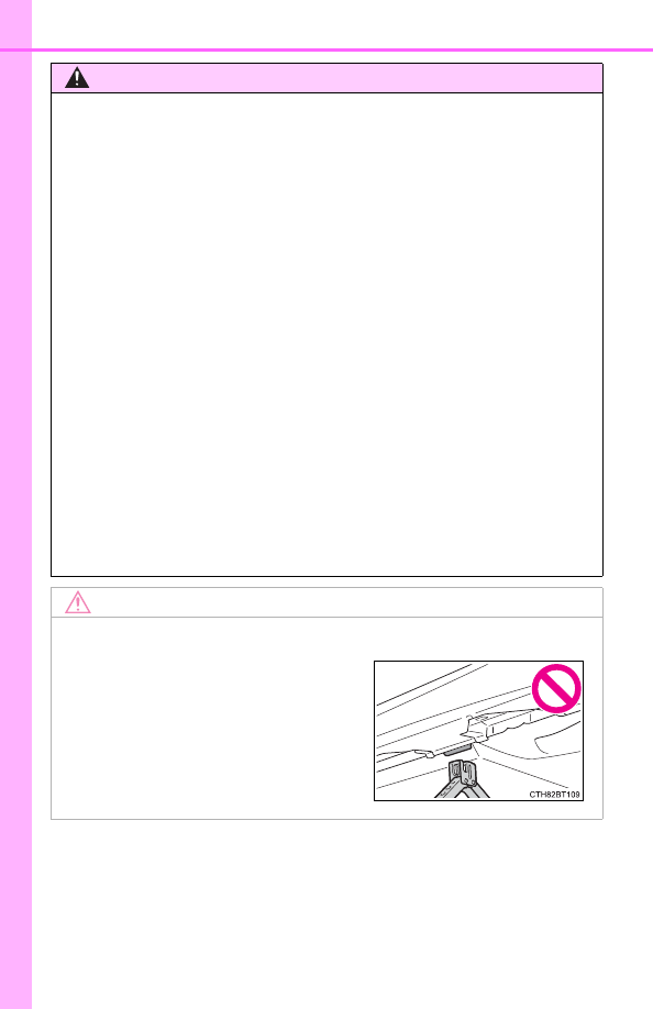
To prevent damage to the vehicle when using a jack

When  jacking  up  the  rear  of  the  vehi-

cle, make sure not to position the jack

under the bracket shown in the illustra-

tion  near  the  rear  jack  point,  as  the

vehicle body may be damaged.

-------------------------------------------------------------------------------------------------------------------------------------------------------------

527

7-2. Steps to take in an emergency

7

W

hen
 troub

le arises

When replacing tires on a vehicle with wheel lock nuts, use the follow-
ing procedures to remove and install the wheel lock nuts. The wheel
lock key is stored in the tray inside the luggage compartment. Always
return  the  wheel  lock  key  to  its  original  position  after  use,  so  that  it
does not get lost. (

P. 525)

Removal

For ease of removal, the wheel lock nut should always be the first
one loosened.

Place  the  wheel  lock  key  on  top  of  the  wheel  lock  nut,  turning
until the wheel lock key and wheel lock nut patterns engage.
Place  the  wheel  nut  wrench  on  the  wheel  lock  key,  and  while
applying pressure on the wheel lock key, loosen the wheel lock
nut.

Installation

For  ease  of  installation,  the  wheel  lock  nut  should  always  be  the
last one tightened.

By hand, install a wheel lock nut on each wheel.
Place  the  wheel  lock  key  on  top  of  the  wheel  lock  nut,  turning
until the wheel lock key and wheel lock nut patterns engage.
Place  the  wheel  nut  wrench  on  the  wheel  lock  key,  and  while
applying pressure on the wheel lock key, tighten the wheel lock
nut to the recommended torque.

Wheel lock nut (if equipped)

NOTICE

When using a wheel lock key

Do not use an impact wrench. Using an impact wrench may cause perma-
nent damage to wheel lock nut and wheel lock key. If in doubt about wheel
lock application, contact your Toyota dealer.

1

2

1

2

3

-------------------------------------------------------------------------------------------------------------------------------------------------------------

528

7-2. Steps to take in an emergency

Lift up the hook of the luggage
floor cover on the trunk floor.

Secure the luggage floor cover
using the hook provided.

Remove the jack.

Lift up the hook of the luggage
floor cover on the trunk floor.

Taking out the jack

1

2

3

Taking out the spare tire

1

-------------------------------------------------------------------------------------------------------------------------------------------------------------

529

7-2. Steps to take in an emergency

7

W

hen
 troub

le arises

Secure the luggage floor cover
using the hook provided.

Remove the tool tray.

Loosen the center fastener that
secures the spare tire.

When  taking  out  or  stowing  the

spare  tire,  make  sure  to  firmly

hold opposite end of the tire.

2

3

4

WARNING

When storing the spare tire

Be careful not to catch fingers or other body parts between the spare

tire and the body of the vehicle.

-------------------------------------------------------------------------------------------------------------------------------------------------------------

530

7-2. Steps to take in an emergency

Chock the tires.

For  vehicles  with  steel  wheels,
remove  the  wheel  ornament
using the wrench.

To  protect  the  wheel  ornament,

place  a  rag  between  the  wrench

and  the  wheel  ornament,  as

shown in the illustration.

Slightly  loosen  the  wheel  nuts
(one turn).

Vehicles  with  wheel  locks:  Use

the wheel lock key to loosen the

wheel lock.

Replacing a flat tire

1

Flat tire

Wheel chock positions

Front

Left-hand side

Behind the rear right-hand side tire

Right-hand side

Behind the rear left-hand side tire

Rear

Left-hand side

In front of the front right-hand side tire

Right-hand side

In front of the front left-hand side tire

2

3

-------------------------------------------------------------------------------------------------------------------------------------------------------------

531

7-2. Steps to take in an emergency

7

W

hen
 troub

le arises

Turn the tire jack portion “A” by
hand until the notch of the jack
is in contact with the jack point.

To prevent damage to the vehicle

when using the jack, position the

jack in the correct location. 

(

P. 526)

The jack point guides are located

under  the  rocker  panel.  They

indicate the jack point positions.

Assemble the jack handle.

Raise the vehicle until the tire is
slightly raised off the ground.

Remove all the wheel nuts and
the tire.

When  resting  the  tire  on  the

ground, place the tire so that the

wheel  design  faces  up  to  avoid

scratching the wheel surface.

4

5

6

7

-------------------------------------------------------------------------------------------------------------------------------------------------------------

532

7-2. Steps to take in an emergency

WARNING

Replacing a flat tire

Do not touch the disc wheels or the area around the brakes immedi-

ately after the vehicle has been driven.

After the vehicle has been driven the disc wheels and the area around

the brakes will be extremely hot. Touching these areas with hands, feet

or other body parts while changing a tire, etc. may result in burns.

Failure  to  follow  these  precautions  could  cause  the  wheel  nuts  to

loosen and the tire to fall off, resulting in death or serious injury.
• Have the wheel nuts tightened with a torque wrench to 76 ft•lbf (103

N•m, 10.5 kgf•m) as soon as possible after changing wheels.

• Do not attach a heavily damaged wheel ornament, as it may fly off

the wheel while the vehicle is moving.

• When installing a tire, only use wheel nuts that have been specifi-

cally designed for that wheel.

• If  there  are  any  cracks  or  deformations  in  the  bolt  screws,  nut

threads  or  bolt  holes  of  the  wheel,  have  the  vehicle  inspected  by

your Toyota dealer.

• When  installing  the  wheel  nuts,  be  sure  to  install  them  with  the

tapered ends facing inward.

-------------------------------------------------------------------------------------------------------------------------------------------------------------

533

7-2. Steps to take in an emergency

7

W

hen
 troub

le arises

Remove any dirt or foreign mat-
ter from the wheel contact sur-
face.

If  foreign  matter  is  on  the  wheel

contact  surface,  the  wheel  nuts

may loosen while the vehicle is in

motion,  causing  the  tire  to  come

off.

Install  the  tire  and  loosely  tighten  each  wheel  nut  by  hand  by
approximately the same amount.
When  replacing  a  steel  wheel
with  a  steel  wheel,  tighten  the
wheel  nuts  until  the  tapered
portion  comes  into  loose  con-
tact with the disc wheel seat.

When  replacing  an  aluminum
wheel  with  a  steel  wheel,
tighten the wheel nuts until the
tapered  portion  comes  into
loose  contact  with  the  disc
wheel seat.

Lower the vehicle.

Installing the spare tire

1

2

Tapered portion

Disc wheel 

seat

Tapered portion

Disc wheel 

seat

3

-------------------------------------------------------------------------------------------------------------------------------------------------------------

534

7-2. Steps to take in an emergency

Firmly  tighten  each  wheel  nut
two  or  three  times  in  the  order
shown in the illustration.

Vehicles  with  wheel  locks:

Tighten the wheel lock using the

wheel  lock  key  after  tightening

the other wheel nuts.
Tightening torque:

76 ft•lbf (103 N•m, 10.5 kgf•m)

Stow the flat tire, tire jack and all tools.

The compact spare tire

The  compact  spare  tire  is  identified  by  the  label  “TEMPORARY  USE

ONLY” on the tire sidewall.

Use the compact spare tire temporarily, and only in an emergency.

Make sure to check the tire inflation pressure of the compact spare tire. 

(

P. 562)

When using the compact spare tire

As  the  compact  spare  tire  is  not  equipped  with  a  tire  pressure  warning

valve and transmitter, low inflation pressure of the spare tire will not be

indicated  by  the  tire  pressure  warning  system. Also,  if  you  replace  the

compact spare tire after the tire pressure warning light comes on, the light

remains on.

When the compact spare tire is equipped

When driving with the compact spare tire installed, the vehicle height will

be different than when driving with standard tires.

If you have a flat front tire on a road covered with snow or ice (vehi-

cles with 16 or 17-inch wheels)

Install  the  compact  spare  tire  on  one  of  the  rear  wheels  of  the  vehicle.

Perform the following steps and fit tire chains to the front tires:

Replace a rear tire with the compact spare tire.
Replace the flat front tire with the tire removed from the rear of the vehi-

cle.
Fit tire chains to the front tires.

4

5

1

2

3

-------------------------------------------------------------------------------------------------------------------------------------------------------------

535

7-2. Steps to take in an emergency

7

W

hen
 troub

le arises

WARNING

When using the compact spare tire

Remember  that  the  compact  spare  tire  provided  is  specifically

designed for use with your vehicle. Do not use your compact spare tire

on another vehicle.

Do not use more than one compact spare tires simultaneously.

Replace the compact spare tire with a standard tire as soon as possi-

ble.

Avoid sudden acceleration, abrupt steering, sudden braking and shift-

ing operations that cause sudden engine braking.

When the compact spare tire is attached

The vehicle speed may not be correctly detected, and the following sys-

tems may not operate correctly:

*

:

If equipped

Speed limit when using the compact spare tire

Do not drive at speeds in excess of 50 mph (80 km/h) when a compact

spare tire is installed on the vehicle.
The compact spare tire is not designed for driving at high speeds. Fail-

ure to observe this precaution may lead to an accident causing death or

serious injury.

After using the tools and jack

Before driving, make sure all the tools and jack are securely in place in

their storage location to reduce the possibility of personal injury during a

collision or sudden braking.

• ABS & Brake assist

• VSC

• TRAC

• EPS

• AHB (Automatic High Beam)

AFS  (Adaptive  Front-lighting

System)

*

• Dynamic  radar  cruise  control

with full-speed range

• LTA (Lane Tracing Assist)

• PCS (Pre-Collision System)

• Tire pressure warning system

• BSM (Blind Spot Monitor)

*

• Intuitive parking assist

*

• PKSB 

(Parking 

Support

Brake)

*

• Rear view monitor system

*

• Toyota parking assist monitor

*

• Panoramic view monitor

*

• Navigation system

*

-------------------------------------------------------------------------------------------------------------------------------------------------------------

536

7-2. Steps to take in an emergency

NOTICE

Be  careful  when  driving  over  bumps  with  the  compact  spare  tire

installed on the vehicle.

The  vehicle  becomes  lower  when  driving  with  the  compact  spare  tire

compared to when driving with standard tires. Be careful when driving

over uneven road surfaces.

Driving with tire chains and the compact spare tire

Do not fit tire chains to the compact spare tire.

Tire chains may damage the vehicle body and adversely affect driving

performance.

When replacing the tires

When removing or fitting the wheels, tires or the tire pressure warning

valve  and  transmitter,  contact  your  Toyota  dealer  as  the  tire  pressure

warning valve and transmitter may be damaged if not handled correctly.

To avoid damage to the tire pressure warning valve and transmit-

ters

When  a  tire  is  repaired  with  liquid  sealants,  the  tire  pressure  warning

valve  and  transmitter  may  not  operate  properly.  If  a  liquid  sealant  is

used, contact your Toyota dealer or other qualified service shop as soon

as possible. Make sure to replace the tire pressure warning valve and

transmitter when replacing the tire. (

P. 457)

-------------------------------------------------------------------------------------------------------------------------------------------------------------

537

7-2. Steps to take in an emergency

7

W

hen
 troub

le arises

One of the following may be the cause of the problem:

The electronic key may not be functioning properly. (

P. 540)

There may not be sufficient fuel in the vehicle’s tank.
Refuel the vehicle.

There may be a malfunction in the immobilizer system. 
(

P. 90)

There may be a malfunction in the steering lock system.

The hybrid system may be malfunctioning due to an electrical prob-
lem such as electronic key battery depletion or a blown fuse. How-
ever, depending on the type of malfunction, an interim measure is
available to start the hybrid system. (

P. 538)

AXVH70 model

*

 only: The temperature of the hybrid battery (traction

battery) may be extremely low (below approximately -22°F [-30°C]). 
(

P. 85, 215)

*

:The model code is indicated on the Certification Label. (

P. 557)

One of the following may be the cause of the problem:

The 12-volt battery may be discharged. (

P. 542)

The 12-volt battery terminal connections may be loose or corroded.
(

P. 451)

If the hybrid system will not start

Reasons for the hybrid system not starting vary depending on
the  situation.  Check  the  following  and  perform  the  appropriate
procedure:

The hybrid system will not start even though the correct starting
procedure is being followed. (

P. 212)

The interior lights and headlights are dim, or the horn does not
sound or sounds at a low volume.

-------------------------------------------------------------------------------------------------------------------------------------------------------------

538

7-2. Steps to take in an emergency

One of the following may be the cause of the problem:

The 12-volt battery may be discharged. (

P. 542)

One or both of the 12-volt battery terminals may be disconnected.
(

P. 451)

Contact your Toyota dealer if the problem cannot be repaired, or if repair
procedures are unknown.

When  the  hybrid  system  does  not  start,  the  following  steps  can  be
used  as  an  interim  measure  to  start  the  hybrid  system  if  the  power
switch is functioning normally.
Do not use this starting procedure except in case of emergency.

Set the parking brake.
Shift the shift lever to P.
Turn the power switch to ACCESSORY mode.
Press  and  hold  the  power  switch  for  about  15  seconds  while
depressing the brake pedal firmly.

Even if the hybrid system can be started using the above steps, the
system  may  be  malfunctioning.  Have  the  vehicle  inspected  by  your
Toyota dealer.

The  interior  lights  and  headlights  do  not  turn  on,  or  the  horn
does not sound.

Emergency start function

1

2

3

4

-------------------------------------------------------------------------------------------------------------------------------------------------------------

539

7-2. Steps to take in an emergency

7

W

hen
 troub

le arises

Doors

Using the mechanical key (

P.

155) in order to perform the fol-
lowing operations (driver’s door
only):

Locks all doors
Closes  the  windows  and  the
moon  roof

*

1

  (turn  and

hold)

*

2

Unlocks the door

Turning the key rearward unlocks the driver's door. Turning the key once
again unlocks the other doors.

Opens the windows and the moon roof

*

1

 (turn and hold)

*

2

*

1

: If equipped

*

2

: This setting must be customized at your Toyota dealer.

If the electronic key does not operate 

properly

If  communication  between  the  electronic  key  and  vehicle  is
interrupted  (

P.  171)  or  the  electronic  key  cannot  be  used

because the battery is depleted, the smart key system and wire-
less  remote  control  cannot  be  used.  In  such  cases,  the  doors
and trunk can be opened and the hybrid system can be started
by following the procedure below.

Locking  and  unlocking  the  doors,  unlocking  the  trunk  and  key
linked functions

1

2

3

4

-------------------------------------------------------------------------------------------------------------------------------------------------------------

540

7-2. Steps to take in an emergency

Trunk

Turn the mechanical key clock-
wise to open.

Ensure  that  the  shift  lever  is  in  P  and  firmly  depress  the  brake
pedal.
Touch  the  Toyota  emblem  side
of  the  electronic  key  to  the
power switch.

When  the  electronic  key  is
detected, a buzzer sounds and the
power switch will turn to ON mode.
When  the  smart  key  system  is
deactivated  in  customization  set-
ting,  the  power  switch  will  turn  to
ACCESSORY mode.

Firmly depress the brake pedal and check that 

 is displayed

on the multi-information display.
Press the power switch shortly and firmly.

In the event that the power switch still cannot be started, contact your
Toyota dealer.

Starting the hybrid system

1

2

3

4

-------------------------------------------------------------------------------------------------------------------------------------------------------------

541

7-2. Steps to take in an emergency

7

W

hen
 troub

le arises

Stopping the hybrid system

Shift the shift lever to P and press the power switch as you normally do when
stopping the hybrid system.

Replacing the key battery

As the above procedure is a temporary measure, it is recommended that the
electronic key battery be replaced immediately when the battery is depleted.
(

P. 482)

Changing power switch modes

Release the brake pedal and press the power switch in step 

 above.

The hybrid system does not start and modes will be changed each time the
switch is pressed. (

P. 214)

When the electronic key does not work properly

Make sure that the smart key system has not been deactivated in the cus-
tomization setting. If it is off, turn the function on. 
(Customizable features: 

P. 581)

Check if battery-saving mode is set. If it is set, cancel the function. 
(

P. 170)

WARNING

When using the mechanical key and operating the power windows or
moon roof 

Operate the power window or moon roof after checking to make sure that
there  is  no  possibility  of  any  passenger  having  any  of  their  body  parts
caught in the window or moon roof. Also, do not allow children to operate
the mechanical key. It is possible for children and other passengers to get
caught in the power window or moon roof.

3

-------------------------------------------------------------------------------------------------------------------------------------------------------------

542

7-2. Steps to take in an emergency

If you have a set of jumper (or booster) cables and a second vehicle
with a 12-volt battery, you can jump start your vehicle by following the
steps below.

Confirm  that  the  electronic  key
is being carried.

When  connecting  the  jumper  (or
booster) cables, depending on the
situation,  the  alarm  may  activate
and doors locked. (

P. 93)

Open the hood and remove the
fuse box cover.

Push the tabs in and lift the lid off.

Open  the  exclusive  jump  start-
ing terminal cover.

If the 12-volt battery is discharged

The following procedures may be used to start the hybrid sys-
tem if the vehicle’s 12-volt battery is discharged.
You can also call your Toyota dealer or a qualified repair shop.

1

2

3

-------------------------------------------------------------------------------------------------------------------------------------------------------------

543

7-2. Steps to take in an emergency

7

W

hen
 troub

le arises

Connect the jumper cables according to the following procedure:

Connect  a  positive  jumper  cable  clamp  to  the  exclusive  jump
starting terminal on your vehicle.
Connect the clamp on the other end of the positive cable to the
positive (+) battery terminal on the second vehicle.
Connect a negative cable clamp to the negative (-) battery termi-
nal on the second vehicle.
Connect  the  clamp  at  the  other  end  of  the  negative  cable  to  a
solid, stationary, unpainted metallic point away from the exclusive
jump  starting  terminal  and  any  moving  parts,  as  shown  in  the
illustration.

4

1

2

3

4

-------------------------------------------------------------------------------------------------------------------------------------------------------------

544

7-2. Steps to take in an emergency

Start the engine of the second vehicle. Increase the engine speed
slightly  and  maintain  at  that  level  for  approximately  5  minutes  to
recharge the 12-volt battery of your vehicle.
Open  and  close  any  of  the  doors  of  your  vehicle  with  the  power
switch off.
Maintain the engine speed of the second vehicle and turn the power
switch to ON mode, then start the vehicle's engine.
Make sure the “READY” indicator comes on. If the indicator does
not come on, contact your Toyota dealer.
Once the hybrid system has started, remove the jumper cables in
the exact reverse order from which they were connected.
Close the exclusive jump starting terminal cover, and reinstall the
fuse box cover to its original position.

Once  the  hybrid  system  starts,  have  the  vehicle  inspected  at  your
Toyota dealer as soon as possible.

5

6

7

8

9

10

-------------------------------------------------------------------------------------------------------------------------------------------------------------

545

7-2. Steps to take in an emergency

7

W

hen
 troub

le arises

Starting the hybrid system when the 12-volt battery is discharged 

The hybrid system cannot be started by push-starting.

To prevent 12-volt battery discharge

Turn off the headlights and the audio system while the hybrid system is off.

Turn off any unnecessary electrical components when the vehicle is running
at a low speed for an extended period, such as in heavy traffic.

When the 12-volt battery is removed or discharged

Information  stored  in  the  ECU  is  cleared.  When  the  12-volt  battery  is
depleted, have the vehicle inspected at your Toyota dealer.

Some systems may require initialization. (

P. 589)

When removing the 12-volt battery terminals

When the 12-volt battery terminals are removed, the information stored in the
ECU is cleared. Before removing the 12-volt battery terminals, contact your
Toyota dealer.

Charging the 12-volt battery

The electricity stored in the 12-volt battery will discharge gradually even when
the vehicle is not in use, due to natural discharge and the draining effects of
certain electrical appliances. If the vehicle is left for a long time, the 12-volt
battery may discharge, and the hybrid system may be unable to start. (The
12-volt battery recharges automatically while the hybrid system is operating.)

When recharging or replacing the 12-volt battery

In some cases, it may not be possible to unlock the doors using the smart
key system when the 12-volt battery is discharged. Use the wireless remote
control or the mechanical key to lock or unlock the doors.

The hybrid system may not start on the first attempt after the 12-volt battery
has recharged but will start normally after the second attempt. This is not a
malfunction.

The power switch mode is memorized by the vehicle. When the 12-volt bat-
tery is reconnected, the system will return to the mode it was in before the
12-volt  battery  was  discharged.  Before  disconnecting  the  12-volt  battery,
turn the power switch off. 
If you are unsure what mode the power switch was in before the 12-volt bat-
tery discharged, be especially careful when reconnecting the 12-volt battery.

-------------------------------------------------------------------------------------------------------------------------------------------------------------

546

7-2. Steps to take in an emergency

When replacing the 12-volt battery

Use a Central Degassing type 12-volt battery (European Regulations).

Vehicles  without  a  moon  roof:  Use  a  12-volt  battery  that  the  case  size  is
same as the previous one (LN2), 20 hour rate capacity (20HR) is equivalent
(55Ah)  or  greater,  and  performance  rating  (CCA)  is  equivalent  (345A)  or
greater.
Vehicles with a moon roof: Use a 12-volt battery that the case size is same
as  the  previous  one  (LN2),  20  hour  rate  capacity  (20HR)  is  equivalent
(60Ah)  or  greater,  and  performance  rating  (CCA)  is  equivalent  (563A)  or
greater.
• If the sizes differ, the 12-volt battery cannot be properly secured.
• If the 20 hour rate capacity is low, even if the time period where the vehi-

cle is not used is a short time, the 12-volt battery may discharge and the
hybrid system may not be able to start.

Use a 12-volt battery with a handle. If a 12-volt battery without a handle is
used, removal is more difficult.

For details, consult your Toyota dealer.

After replacing, firmly attach the follow-
ing items to the exhaust hole of the 12-
volt battery.
• Use  the  exhaust  hose  that  was

attached to the 12-volt battery before
replacing and confirm that it is firmly
connected to the hole section of the
vehicle.

• Use  the  exhaust  hole  plug  included

with  the  12-volt  battery  replaced  or
the one installed on the battery prior
to  the  replacement.  (Depending  on
the 12-volt battery to be replaced, the
exhaust hole may be plugged.)

Exhaust hole plug
Exhaust hole
Exhaust hose
Hole section of the vehicle

1

2

3

4

-------------------------------------------------------------------------------------------------------------------------------------------------------------

547

7-2. Steps to take in an emergency

7

W

hen
 troub

le arises

WARNING

When removing the 12-volt battery terminals

Always remove the negative (-) terminal first. If the positive (+) terminal con-
tacts  any  metal  in  the  surrounding  area  when  the  positive  (+)  terminal  is
removed, a spark may occur, leading to a fire in addition to electrical shocks
and death or serious injury.

Avoiding 12-volt battery fires or explosions

Observe the following precautions to prevent accidentally igniting the flam-
mable gas that may be emitted from the 12-volt battery:

Make sure each jumper cable is connected to the correct terminal and that
it is not unintentionally in contact with any other than the intended terminal.

Do not allow the other end of the jumper cable connected to the “+” termi-
nal to come into contact with any other parts or metal surfaces in the area,
such as brackets or unpainted metal.

Do not allow the + and - clamps of the jumper cables to come into contact
with each other.

Do  not smoke,  use matches, cigarette lighters  or  allow  open flame near
the 12-volt battery.

12-volt battery precautions

The  12-volt  battery  contains  poisonous  and  corrosive  acidic  electrolyte,
while related parts contain lead and lead compounds. Observe the following
precautions when handling the 12-volt battery:

When  working  with  the  12-volt  battery,  always  wear  safety  glasses  and
take care not to allow any battery fluids (acid) to come into contact with
skin, clothing or the vehicle body.

Do not lean over the 12-volt battery.

In  the  event  that  battery  fluid  comes  into  contact  with  the  skin  or  eyes,
immediately wash the affected area with water and seek medical attention.
Place a wet sponge or cloth over the affected area until medical attention
can be received.

Always wash your hands after handling the 12-volt battery support, termi-
nals, and other 12-volt battery-related parts.

Do not allow children near the 12-volt battery.

After recharging the 12-volt battery

Have the 12-volt battery inspected at your Toyota dealer as soon as possi-
ble.
If the 12-volt battery is deteriorating, continued use may cause the 12-volt
battery to emit a malodorous gas, which may be detrimental to the health of
passengers.

-------------------------------------------------------------------------------------------------------------------------------------------------------------

548

7-2. Steps to take in an emergency

WARNING

When replacing the 12-volt battery

After replacing, securely attach the exhaust hose and exhaust hole plug to
the  exhaust  hole  of  the  replaced  12-volt  battery.  If  not  properly  installed,
gases (hydrogen) may leak into the vehicle interior, and there is the possi-
ble danger of the gas igniting and exploding.

NOTICE

When handling jumper cables

When connecting the jumper cables, ensure that they do not become entan-
gled in the cooling fan or engine drive belt.

To prevent damaging the vehicle

The exclusive jump starting terminal is to be used when charging the 12-volt
battery  from  another  vehicle  in  an  emergency.  It  cannot  be  used  to  jump
start another vehicle.

-------------------------------------------------------------------------------------------------------------------------------------------------------------

549

7-2. Steps to take in an emergency

7

W

hen
 troub

le arises

If the needle of the engine coolant temperature gauge enters
the  red  zone  or  “Engine  Coolant  Temp  High  Stop  in  a  Safe
Place See Owner’s Manual” is shown on the multi-information
display

Stop the vehicle in a safe place and turn off the air conditioning sys-
tem, and then stop the hybrid system.
If you see steam: 
Carefully lift the hood after the steam subsides.
If you do not see steam:
Carefully lift the hood.
After  the  hybrid  system  has
cooled 

down 

sufficiently,

inspect  the  hoses  and  radiator
core (radiator) for any leaks.

Radiator
Cooling fan

If a large amount of coolant leaks,
immediately  contact  your  Toyota
dealer.

If your vehicle overheats

The following may indicate that your vehicle is overheating.

The needle of the engine coolant temperature gauge (

P. 102)

enters  the  red  zone or a loss  of  hybrid  system  power  is  experi-
enced. (For example, the vehicle speed does not increase.)

“Engine  Coolant Temp  High  Stop  in  a  Safe  Place  See  Owner’s
Manual” or “Hybrid System Overheated Output Power Reduced”
is shown on the multi-information display

Steam comes out from under the hood.

Correction procedures

1

2

3

1

2

-------------------------------------------------------------------------------------------------------------------------------------------------------------

550

7-2. Steps to take in an emergency

The coolant level is satisfactory
if  it  is  between  the  “F”  and  “L”
lines on the reservoir.

Reservoir
“F” line
“L” line
Radiator cap

Add coolant if necessary.

Water  can  be  used  in  an  emer-
gency if coolant is unavailable.

Start the hybrid system and turn the air conditioning system on to
check that the radiator cooling fan operates and to check for cool-
ant leaks from the radiator or hoses.

The fan operates when the air conditioning system is turned on immedi-
ately after a cold start. Confirm that the fan is operating by checking the fan
sound and air flow. If it is difficult to check these, turn the air conditioning
system on and off repeatedly. (The fan may not operate in freezing tem-
peratures.)

If the fan is not operating: 
Stop the hybrid system immediately and contact your Toyota dealer.
If the fan is operating: 
Have the vehicle inspected at the nearest Toyota dealer.

4

1

2

3

4

5

6

7

-------------------------------------------------------------------------------------------------------------------------------------------------------------

551

7-2. Steps to take in an emergency

7

W

hen
 troub

le arises

If  “Hybrid  System  Overheated  Output  Power  Reduced”  is
shown on the multi-information display

Stop the vehicle in a safe place.
Stop the hybrid system and carefully lift the hood.
After  the  hybrid  system  has
cooled  down,  inspect  the
hoses  and  radiator  core
(radiator) for any leaks.

Radiator
Cooling fan

If  a  large  amount  of  coolant
leaks,  immediately  contact
your Toyota dealer.

The coolant level is satisfac-
tory  if  it  is  between  the
“FULL”  and  “LOW”  lines  on
the reservoir.

Reservoir
“FULL”
“LOW”

Add coolant if necessary.

Water can be used in an emer-
gency if coolant is unavailable.

1

2

3

1

2

4

1

2

3

5

-------------------------------------------------------------------------------------------------------------------------------------------------------------

552

7-2. Steps to take in an emergency

After  stopping  the  hybrid  system  and  waiting  for  5  minutes  or
more, start the hybrid system again and check for the multi-infor-
mation display.
If the message does not disappear:

Stop the hybrid system and contact your Toyota dealer.

If the message is not displayed:

The hybrid system temperature has dropped and the vehicle
may be driven normally.

However, if the message appears again frequently, contact your Toyota
dealer.

WARNING

To  prevent  an  accident  or  injury  when  inspecting  under  the  hood  of
your vehicle

Observe the following precautions. 
Failure to do so may result in serious injury such as burns.

If steam is seen coming from under the hood, do not open the hood until
the steam has subsided. The engine compartment may be very hot.

After the hybrid system has been turned off, check that the “READY” indi-
cator is off. When the hybrid system is operating, the gasoline engine may
automatically  start,  or  the  cooling  fan  may  suddenly  operate  even  if  the
gasoline engine stops. Do not touch or approach rotating parts such as the
fan, which may lead to fingers or clothing (especially a tie, a scarf or a muf-
fler) getting caught, resulting in serious injury.

Do  not  loosen  the  radiator  cap  and  the  coolant  reservoir  cap  while  the
hybrid system and radiator are hot.
High temperature steam or coolant could spray out.

NOTICE

When adding engine/power control unit coolant

Wait until the hybrid system has cooled down before adding engine/power
control unit coolant.
When adding coolant, do so slowly. Adding cool coolant to a hot hybrid sys-
tem too quickly can cause damage to the hybrid system.

To prevent damage to the cooling system

Observe the following precautions:

Avoid contaminating the coolant with foreign matter (such as sand or dust
etc.).

Do not use any coolant additives.

6

-------------------------------------------------------------------------------------------------------------------------------------------------------------

553

7-2. Steps to take in an emergency

7

W

hen
 troub

le arises

Stop  the  hybrid  system.  Set  the  parking  brake  and  shift  the  shift
lever to P.
Remove the mud, snow or sand from around the front wheels.
Place wood, stones or some other material under the front wheels
to help provide traction.
Restart the hybrid system.
Shift the shift lever to D or R and release the parking brake. Then,
while exercising caution, depress the accelerator pedal.

When it is difficult to free the vehicle

If the vehicle becomes stuck

Carry out the following procedures if the tires spin or the vehicle
becomes stuck in mud, dirt or snow:

1

2

3

4

5

Press 

 to turn off TRAC.

WARNING

When attempting to free a stuck vehicle

If you choose to push the vehicle back and forth to free it, make sure the
surrounding area is clear to avoid striking other vehicles, objects or people.
The vehicle may also lunge forward or lunge back suddenly as it becomes
free. Use extreme caution.

When shifting the shift lever

Be careful not to shift the shift lever with the accelerator pedal depressed.
This  may  lead  to  unexpected  rapid  acceleration  of  the  vehicle  that  may
cause an accident resulting in death or serious injury.

-------------------------------------------------------------------------------------------------------------------------------------------------------------

554

7-2. Steps to take in an emergency

NOTICE

To avoid damaging the transmission and other components

Avoid  spinning  the  front  wheels  and  depressing  the  accelerator  pedal
more than necessary.

If  the  vehicle  remains  stuck even  after  these procedures  are  performed,
the vehicle may require towing to be freed.

-------------------------------------------------------------------------------------------------------------------------------------------------------------

-------------------------------------------------------------------------------------------------------------------------------------------------------------

556

8-1. Specifications

*

1

: Unladen vehicles

*

2

: For LE or XLE grade models

*

3

: For SE or XSE grade models

*

4

: 205/65R16 tires

*

5

: 215/55R17 tires

*

6

: 235/45R18 and 235/40R19 tires

Maintenance data (fuel, oil level, etc.)

Dimensions and weights

Overall length

192.1 in. (4880 mm)

*

2

192.7 in. (4895 mm)

*

3

Overall width

72.4 in. (1840 mm)

Overall height

*

1

56.9 in. (1445 mm)

Wheelbase

111.2 in. (2825 mm)

Tread

*

1

Front

63.0 in. (1600 mm)

*

4

62.6 in. (1590 mm)

*

5

62.2 in. (1580 mm)

*

6

Rear

63.2 in. (1605 mm)

*

4

62.8 in. (1595 mm)

*

5

62.6 in. (1590 mm)

*

6

Vehicle capacity weight
(occupants + luggage)

925 lb. (420 kg)

Seating capacity

Seating capacity

5 (Front 2, Rear 3)

-------------------------------------------------------------------------------------------------------------------------------------------------------------

557

8-1. Specifications

8

Ve
hicle

 spe
cifi

cations

Vehicle identification number

The  vehicle  identification  number  (VIN)  is  the  legal  identifier  for
your  vehicle.  This  is  the  primary  identification  number  for  your
Toyota. It is used in registering the ownership of your vehicle.
This number is stamped on the
top left of the instrument panel.

This number is also on the Cer-
tification Label.

Engine number

The engine number is stamped
on the engine block as shown.

Vehicle identification

-------------------------------------------------------------------------------------------------------------------------------------------------------------

558

8-1. Specifications

*

: Checking your vehicle’s model: 

P. 557

Engine

Model

A25A-FXS

Type

4-cylinder in line, 4-cycle, gasoline

Bore and stroke

3.44 

 4.07 in. (87.5 

 103.4 mm)

Displacement

151.8 cu. in. (2487 cm

3

)

Valve clearance

Automatic adjustment

Fuel

Fuel type

Unleaded gasoline only

Octane rating

87 (Research Octane Number 91) or higher

Fuel tank capacity
(Reference)

13 gal. (49.3 L, 10.8 Imp. gal.)

Electric motor (Traction motor)

Type

Permanent magnet synchronous motor

Maximum output

88 kW

Maximum torque

149 ft

•lbf (202 N•m, 20.6 kgf•m)

Hybrid battery (Traction battery)

AXVH70 model

*

AXVH71 models

*

Type

Lithium-ion battery

Nickel-metal hydride bat-
tery

Voltage

3.7 V/cell

7.2 V/module

Capacity

4.0 Ah

6.5 Ah (3HR)

Quantity

70 cells

34 modules

Nominal voltage

259 V

244.8 V

-------------------------------------------------------------------------------------------------------------------------------------------------------------

559

8-1. Specifications

8

Ve
hicle

 spe
cifi

cations

Oil capacity (Drain and refill [Reference

*

])

*

: The engine oil capacity is a reference quantity to be used when changing

the  engine  oil.  Warm  up  the  engine  and  turn  off  the  hybrid  system,  wait
more than 5 minutes, and check the oil level on the dipstick.

Engine oil selection

“Toyota  Genuine  Motor  Oil”  is  used  in  your  Toyota  vehicle.  Use
Toyota approved “Toyota Genuine Motor Oil” or equivalent to sat-
isfy the following grade and viscosity.
Oil grade: API SN/RC multigrade engine oil
Recommended viscosity: SAE 0W-16

SAE  0W-16  is  the  best  choice  for
good fuel economy and good start-
ing in cold weather.
If SAE 0W-16 is not available, SAE
0W-20  oil  may  be  used.  However,
it  must  be  replaced  with SAE 0W-
16 at the next oil change.

Oil viscosity (0W-16 is explained here as an example):

• The 0W in 0W-16 indicates the characteristic of the oil which allows cold

startability. Oils with a lower value before the W allow for easier starting of
the engine in cold weather.

• The 16 in 0W-16 indicates the viscosity characteristic of the oil when the

oil is at high temperature. An oil with a higher viscosity (one with a higher
value) may be better suited if the vehicle is operated at high speeds, or
under extreme load conditions.

How to read oil container label:
API registered mark is added to
some oil containers to help you
select the oil you should use.

Lubrication system

With filter

4.8 qt. (4.5 L, 4.0 Imp. qt.)

Without filter

4.4 qt. (4.2 L, 3.7 Imp. qt.)

Outside temperature

-------------------------------------------------------------------------------------------------------------------------------------------------------------

560

8-1. Specifications

Cooling system 

Capacity 
(Reference)

Gasoline engine

6.4 qt. (6.1 L, 5.4 Imp. qt.)

Power control unit

1.9 qt. (1.8 L, 1.6 Imp. qt.)

Coolant type

Use either of the following:

• “Toyota Super Long Life Coolant” 
• Similar  high-quality  ethylene  glycol-based

non-silicate,  non-amine,  non-nitrite,  and
non-borate  coolant  with  long-life  hybrid
organic acid technology

Do not use plain water alone.

Ignition system

Spark plug

Make

DENSO FC16HR-Q8

Gap

0.031 in. (0.8 mm)

NOTICE

Iridium-tipped spark plugs

Use only iridium-tipped spark plugs. Do not adjust spark plug gap.

-------------------------------------------------------------------------------------------------------------------------------------------------------------

561

8-1. Specifications

8

Ve
hicle

 spe
cifi

cations

*

: The fluid capacity is a reference quantity. 

If replacement is necessary, contact your Toyota dealer. 

*

: Minimum pedal clearance when depressed with a force of 67 lbf (300 N, 31

kgf) while the hybrid system is operating.

Electrical system

12-volt battery

Open voltage at 
 68

F (20

C):

12.0 V or higher 
If  the  voltage  is  lower  than  the  standard  value,
charge the battery. 
(When  checking  the  voltage,  after  turning  the
power  switch  off,  wait  for  30  seconds  with  the
high  beam  headlights  illuminated,  then  turn  the
high beam headlights off and check the voltage.)

Charging rates

5 A max.

Hybrid transmission

Fluid capacity

*

4.1 qt. (3.9 L, 3.4 Imp. qt.)

Fluid type

Toyota Genuine ATF WS

NOTICE

Hybrid transmission fluid type

Using  transmission  fluid  other  than  the  above  type  may  cause  abnormal
noise or vibration, or ultimately damage the transmission of your vehicle.

Brakes

Pedal clearance

*

3.3 in. (85 mm)

Pedal free play

0.04 

 0.24 in. (1 

 6 mm)

Brake pad wear limit

0.04 in. (1.0 mm)

Fluid type

FMVSS No.116 DOT 3 or SAE J1703
FMVSS No.116 DOT 4 or SAE J1704

Steering

Free play

Less than 1.2 in. (30 mm)

-------------------------------------------------------------------------------------------------------------------------------------------------------------

562

8-1. Specifications

Type A

Type B

Tires and wheels

Tire size

205/65R16 95H, T155/70D17 110M

Tire inflation pressure

(Recommended  cold  tire

inflation pressure)

Driving under normal conditions

Front: 

35 psi (240 kPa, 2.4 kgf/cm

2

 or bar)

Rear: 

35 psi (240 kPa, 2.4 kgf/cm

2

 or bar)

Spare: 

60 psi (420 kPa, 4.2 kgf/cm

2

 or bar)

Driving  at  high  speeds  (above  100  mph

[160  km/h])  (in  countries  where  such

speeds are permitted by law)

Add 5 psi (30 kPa, 0.3 kgf/cm

2

 or bar) to

the  front  tires  and  rear  tires.  Never

exceed  the  maximum  cold  tire  inflation

pressure indicated on the tire sidewall.

Wheel size

16 

 6 1/2 J, 17 

 4 T (compact spare)

Wheel nut torque

76 ft•lbf (103 N•m, 10.5 kgf•m)

Tire size

215/55R17 94V, T155/70D17 110M

Tire inflation pressure

(Recommended  cold  tire

inflation pressure)

Driving under normal conditions

Front: 

35 psi (240 kPa, 2.4 kgf/cm

2

 or bar)

Rear: 

35 psi (240 kPa, 2.4 kgf/cm

2

 or bar)

Spare: 

60 psi (420 kPa, 4.2 kgf/cm

2

 or bar)

Driving  at  high  speeds  (above  100  mph

[160  km/h])  (in  countries  where  such

speeds are permitted by law)

Add 5 psi (30 kPa, 0.3 kgf/cm

2

 or bar) to

the  front  tires  and  rear  tires.  Never

exceed  the  maximum  cold  tire  inflation

pressure indicated on the tire sidewall.

Wheel size

17 

 7 1/2 J, 17 

 4 T (compact spare)

Wheel nut torque

76 ft•lbf (103 N•m, 10.5 kgf•m)

-------------------------------------------------------------------------------------------------------------------------------------------------------------

563

8-1. Specifications

8

Ve
hicle

 spe
cifi

cations

Type C

Tire size

235/45R18 94V, T155/70D17 110M

Tire inflation pressure

(Recommended  cold  tire

inflation pressure)

Driving under normal conditions

Front: 

35 psi (240 kPa, 2.4 kgf/cm

2

 or bar)

Rear: 

35 psi (240 kPa, 2.4 kgf/cm

2

 or bar)

Spare: 

60 psi (420 kPa, 4.2 kgf/cm

2

 or bar)

Driving  at  high  speeds  (above  100  mph

[160  km/h])  (in  countries  where  such

speeds are permitted by law)

Add 5 psi (30 kPa, 0.3 kgf/cm

2

 or bar) to

the  front  tires  and  rear  tires.  Never

exceed  the  maximum  cold  tire  inflation

pressure indicated on the tire sidewall.

Wheel size

18 

 8 J, 17 

 4 T (compact spare)

Wheel nut torque

76 ft•lbf (103 N•m, 10.5 kgf•m)

-------------------------------------------------------------------------------------------------------------------------------------------------------------

564

8-1. Specifications

*

1

: Light bulbs not listed in this table are LED bulbs.

*

2

: If equipped

Light bulbs

*

1

Light bulbs

Bulb No.

W

Type

Exterior

Front  side  marker
lights (bulb type)

W5W

5

A

Front turn signal/
parking lights 
(bulb type)

7444NA

28/8

B

Rear turn signal lights
(bulb type)

WY21W

21

B

Rear 

side 

marker

lights (bulb type)

W5W

5

A

Back-up lights 
(bulb type)

921

16

A

Interior

Rear interior light

*

2

8

C

Door courtesy lights

*

2

5

A

Vanity lights

*

2

8

A

Trunk light

5

A

A: Wedge base bulbs (clear)

C: Double end bulbs

B: Wedge base bulbs (amber)

-------------------------------------------------------------------------------------------------------------------------------------------------------------

565

8-1. Specifications

8

Ve
hicle

 spe
cifi

cations

Gasoline quality

In very few cases, driveability problems may be caused by the brand of gaso-
line you are using. If driveability problems persist, try changing the brand of
gasoline. If this does not correct the problem, consult your Toyota dealer.

Recommendation of the use of gasoline containing detergent additives

Toyota recommends the use of gasoline that contains detergent additives to
avoid the build-up of engine deposits.

All  gasoline  sold  in  the  U.S.A.  contains  minimum  detergent  additives  to
clean and/or keep clean intake systems, per EPA’s lowest additives concen-
tration program.

Toyota  strongly  recommends  the  use  of Top Tier  Detergent  Gasoline.  For
more  information  on Top Tier  Detergent  Gasoline  and  a  list  of  marketers,
please go to the official website www.toptiergas.com.

Recommendation of the use of low emissions gasoline

Gasolines  containing  oxygenates  such  as  ethers  and  ethanol,  as  well  as
reformulated gasolines, are available in some cities. These fuels are typically
acceptable for use, providing they meet other fuel requirements.
Toyota  recommends  these  fuels,  since  the  formulations  allow  for  reduced
vehicle emissions.

Fuel information

You must only use unleaded gasoline.
Select octane rating 87 (Research Octane Number 91) or higher.
Use  of  unleaded  gasoline  with  an  octane  rating  lower  than  87
may result in engine knocking. Persistent knocking can lead to
engine damage.

At minimum, the gasoline you use should meet the specifications of
ASTM D4814 in the U.S.A..

-------------------------------------------------------------------------------------------------------------------------------------------------------------

566

8-1. Specifications

Non-recommendation of the use of blended gasoline

If you use gasohol in your vehicle, be sure that it has an octane rating no
lower than 87.

Toyota does not recommend the use of gasoline containing methanol.

Non-recommendation of the use of gasoline containing MMT

Some gasoline contains an octane enhancing additive called MMT (Methylcy-
clopentadienyl Manganese Tricarbonyl).
Toyota  does  not  recommend  the  use  of  gasoline  that  contains  MMT.  If  fuel
containing  MMT  is  used,  your  emission  control  system  may  be  adversely
affected.
The malfunction indicator lamp on the instrument cluster may come on. If this
happens, contact your Toyota dealer for service.

If your engine knocks

Consult your Toyota dealer.

You may occasionally notice light knocking for a short time while accelerat-
ing or driving uphill. This is normal and there is no need for concern.

Use only gasoline containing up to 15%
ethanol.
DO  NOT  use  any  flex-fuel  or  gasoline
that could contain more than 15% etha-
nol,  including  from  any  pump  labeled
E30,  E50,  E85  (which  are  only  some
examples  of  fuel  containing  more  than
15% ethanol).

DO NOT use gasoline contain-
ing more than 15% ethanol.

(30% ethanol)

(50% ethanol)

(85% ethanol)

-------------------------------------------------------------------------------------------------------------------------------------------------------------

567

8-1. Specifications

8

Ve
hicle

 spe
cifi

cations

NOTICE

Notice on fuel quality

Do not use improper fuels. If improper fuels are used, the engine will be
damaged.

Do not use leaded gasoline.
Leaded gasoline can cause damage to your vehicle’s three-way catalytic
converters causing the emission control system to malfunction.

Do not use gasohol other than the type previously stated.
Other  gasohol  may  cause  fuel  system  damage  or  vehicle  performance
problems.

Using unleaded gasoline with an octane number or rating lower than the
level previously stated will cause persistent heavy knocking.
At worst, this will lead to engine damage.

Fuel-related poor driveability

If poor driveability (poor hot starting, vaporization, engine knocking, etc.) is
encountered after using a different type of fuel, discontinue the use of that
type of fuel.

When refueling with gasohol

Take care not to spill gasohol. It can damage your vehicle’s paint.

-------------------------------------------------------------------------------------------------------------------------------------------------------------

568

8-1. Specifications

Full-size tire

Compact spare tire

Tire information

Typical tire symbols

-------------------------------------------------------------------------------------------------------------------------------------------------------------

569

8-1. Specifications

8

Ve
hicle

 spe
cifi

cations

Tire size (

P. 571)

Summer tires or all season tires (

P. 462)

An all season tire has “M+S” on the sidewall. A tire not marked “M+S”

is a summer tire.

TUBELESS or TUBE TYPE

A tubeless tire does not have a tube and air is directly put into the tire.

A tube type tire has a tube inside the tire and the tube maintains the air

pressure.

Radial tires or bias-ply tires

A radial tire has “RADIAL” on the sidewall. A tire not marked “RADIAL”

is a bias-ply tire.

DOT and Tire Identification Number (TIN) (

P. 570)

Location of treadwear indicators (

P. 455)

Uniform tire quality grading

For details, see “Uniform Tire Quality Grading” that follows.

Maximum cold tire inflation pressure (

P. 562)

This means the pressure to which a tire may be inflated.

Load limit at maximum cold tire inflation pressure (

P. 461)

Tire ply composition and materials

Plies are layers of rubber-coated parallel cords. Cords are the strands

which form the plies in a tire.

“TEMPORARY USE ONLY”

A  compact  spare  tire  is  identified  by  the  phrase  “TEMPORARY  USE

ONLY”  molded  on  its  sidewall.  This  tire  is  designed  for  temporary

emergency use only.

1

2

3

4

5

6

7

8

9

10

11

-------------------------------------------------------------------------------------------------------------------------------------------------------------

570

8-1. Specifications

DOT symbol

*

Tire Identification Number (TIN)
Tire manufacturer’s identification mark
Tire size code
Manufacturer’s optional tire type code (3 or 4 letters)
Manufacturing week
Manufacturing year
Manufacturer’s code

*

: The DOT symbol certifies that the tire conforms to applicable Federal

Motor Vehicle Safety Standards.

Typical DOT and Tire Identification Number (TIN)

Type A

Type B

1

2

3

4

5

6

7

8

-------------------------------------------------------------------------------------------------------------------------------------------------------------

571

8-1. Specifications

8

Ve
hicle

 spe
cifi

cations

Typical tire size information

The illustration indicates typical
tire size.

Tire use 
(P  =  Passenger  car  [some-
times omitted],
T = Temporary use)
Section width (millimeters)
Aspect ratio 
(tire height to section width)
Tire construction code (R = Radial, D = Diagonal)
Wheel diameter (inches)
Load index (2 digits or 3 digits)
Speed symbol (alphabet with one letter)

Tire dimensions

Section width
Tire height
Wheel diameter

Tire size

1

2

3

4

5

6

7

1

2

3

-------------------------------------------------------------------------------------------------------------------------------------------------------------

572

8-1. Specifications

Bead
Sidewall
Shoulder
Tread
Belt
Inner liner
Reinforcing rubber
Carcass
Rim lines
Bead wires
Chafer

Tire section names

1

2

3

4

5

6

7

8

9

10

11

-------------------------------------------------------------------------------------------------------------------------------------------------------------

573

8-1. Specifications

8

Ve
hicle

 spe
cifi

cations

This  information  has  been  prepared  in  accordance  with  regulations
issued  by  the  National  Highway  Traffic  Safety Administration  of  the
U.S. Department of Transportation.
It  provides  the  purchasers  and/or  prospective  purchasers  of  Toyota
vehicles with information on uniform tire quality grading.

Your Toyota  dealer  will  help  answer  any  questions  you  may  have  as

you read this information.

DOT quality grades

All passenger vehicle tires must conform to Federal Safety Require-
ments  in  addition  to  these  grades.  Quality  grades  can  be  found
where applicable on the tire sidewall between tread shoulder and
maximum section width.

For example: Treadwear 200 Traction AA Temperature A

Treadwear

The  treadwear  grade  is  a  comparative  rating  based  on  the  wear
rate of the tire when tested under controlled conditions on a speci-
fied government test course.

For example, a tire graded 150 would wear one and a half (1 - 1/2)

times as well on the government course as a tire graded 100.

The  relative  performance  of  tires  depends  upon  the  actual  condi-

tions of their use. Performance may differ significantly from the norm

due to variations in driving habits, service practices and differences

in road characteristics and climate.

Traction AA, A, B, C

The  traction  grades,  from  highest  to  lowest,  are AA, A,  B  and  C,
and  they  represent  the  tire’s  ability  to  stop  on  wet  pavement  as
measured under controlled conditions on specified government test
surfaces of asphalt and concrete.

A tire marked C may have poor traction performance.
Warning: The traction grade assigned to this tire is based on braking

(straight ahead) traction tests and does not include cornering (turn-

ing) traction.

Uniform Tire Quality Grading

-------------------------------------------------------------------------------------------------------------------------------------------------------------

574

8-1. Specifications

Temperature A, B, C

The temperature grades are A (the highest), B, and C, representing
the tire’s resistance to the generation of heat and its ability to dissi-
pate  heat  when  tested  under  controlled  conditions  on  a  specified
indoor laboratory test wheel.

Sustained  high  temperature  can  cause  the  material  of  the  tire  to

degenerate and reduce tire life, and excessive temperature can lead

to sudden tire failure.
Grade C corresponds to a level of performance which all passenger

car  tires  must  meet  under  the  Federal  Motor  Vehicle  Safety  Stan-

dard No. 109.
Grades B and A represent higher levels of performance on the labo-

ratory test wheel than the minimum required by law.
Warning: The temperature grades of a tire assume that it is properly

inflated and not overloaded.

Excessive speed, underinflation, or excessive loading, either sepa-

rately  or  in  combination,  can  cause  heat  buildup  and  possible  tire

failure.

-------------------------------------------------------------------------------------------------------------------------------------------------------------

575

8-1. Specifications

8

Ve
hicle

 spe
cifi

cations

Glossary of tire terminology

Tire related term

Meaning

Cold tire inflation pres-

sure

Tire  pressure  when  the  vehicle  has  been

parked  for  three  hours  or  more,  or  has  not

been driven more than 1 mile or 1.5 km under

that condition

Maximum 

inflation

pressure

The maximum cold inflated pressure to which

a tire may be inflated, shown on the sidewall

of the tire

Recommended  infla-

tion pressure

Cold tire inflation pressure recommended by a

manufacturer

Accessory weight

The combined weight (in excess of those stan-

dard  items  which  may  be  replaced)  of  auto-

matic  transmission,  power  steering,  power

brakes,  power  windows,  power  seats,  radio

and heater, to the extent that these items are

available  as  factory-installed  equipment

(whether installed or not)

Curb weight

The  weight  of  a  motor  vehicle  with  standard

equipment, including the maximum capacity of

fuel,  oil  and  coolant,  and  if  so  equipped,  air

conditioning  and  additional  weight  optional

engine

Maximum loaded vehi-

cle weight

The sum of:

(a) Curb weight

(b) Accessory weight

(c) Vehicle capacity weight

(d) Production options weight

Normal 

occupant

weight

150 lb. (68 kg) times the number of occupants

specified  in  the  second  column  of  Table  1

*

that follows

Occupant distribution

Distribution of occupants in a vehicle as speci-

fied in the third column of Table 1

*

 below

-------------------------------------------------------------------------------------------------------------------------------------------------------------

576

8-1. Specifications

Production 

options

weight

The combined weight of installed regular pro-

duction options weighing over 5 lb. (2.3 kg) in

excess  of  the  standard  items  which  they

replace,  not  previously  considered  in  curb

weight  or  accessory  weight,  including  heavy

duty  brakes,  ride  levelers,  roof  rack,  heavy

duty battery, and special trim

Rim

A  metal  support  for  a  tire  or  a  tire  and  tube

assembly  upon  which  the  tire  beads  are

seated

Rim diameter

(Wheel diameter)

Nominal diameter of the bead seat

Rim size designation

Rim diameter and width

Rim type designation

The industry manufacturer’s designation for a

rim by style or code

Rim width

Nominal distance between rim flanges

Vehicle 

capacity

weight 

(Total 

load

capacity)

The rated cargo and luggage load plus 150 lb.

(68 kg) times the vehicle’s designated seating

capacity

Vehicle maximum load

on the tire

The  load  on  an  individual  tire  that  is  deter-

mined by distributing to each axle its share of

the  maximum  loaded  vehicle  weight,  and

dividing by two

Vehicle normal load on

the tire

The  load  on  an  individual  tire  that  is  deter-

mined by distributing to each axle its share of

curb  weight,  accessory  weight,  and  normal

occupant  weight  (distributed  in  accordance

with Table 1

*

 below), and dividing by two

Weather side

The surface area of the rim not covered by the

inflated tire

Bead

The part of the tire that is made of steel wires,

wrapped or reinforced by ply cords and that is

shaped to fit the rim

Bead separation

A  breakdown  of  the  bond  between  compo-

nents in the bead

Tire related term

Meaning

-------------------------------------------------------------------------------------------------------------------------------------------------------------

577

8-1. Specifications

8

Ve
hicle

 spe
cifi

cations

Bias ply tire

A  pneumatic  tire  in  which  the  ply  cords  that

extend  to  the  beads  are  laid  at  alternate

angles  substantially  less  than  90  degrees  to

the centerline of the tread

Carcass

The  tire  structure,  except  tread  and  sidewall

rubber which, when inflated, bears the load

Chunking

The  breaking  away  of  pieces  of  the  tread  or

sidewall

Cord

The strands forming the plies in the tire

Cord separation

The  parting  of  cords  from  adjacent  rubber

compounds

Cracking

Any parting within the tread, sidewall, or inner-

liner of the tire extending to cord material

CT

A  pneumatic  tire  with  an  inverted  flange  tire

and  rim  system  in  which  the  rim  is  designed

with  rim  flanges  pointed  radially  inward  and

the  tire  is  designed  to  fit  on  the  underside  of

the  rim  in  a  manner  that  encloses  the  rim

flanges inside the air cavity of the tire

Extra load tire

A tire designed to operate at higher loads and

at  higher  inflation  pressures  than  the  corre-

sponding standard tire

Groove

The space between two adjacent tread ribs

Innerliner

The  layer(s)  forming  the  inside  surface  of  a

tubeless tire that contains the inflating medium

within the tire

Innerliner separation

The parting of the innerliner from cord material

in the carcass

Intended 

outboard

sidewall

(a) The  sidewall  that  contains  a  whitewall,

bears  white  lettering,  or  bears  manufac-

turer,  brand,  and/or  model  name  molding

that  is  higher  or  deeper  than  the  same

molding on the other sidewall of the tire, or

(b) The  outward  facing  sidewall  of  an  asym-

metrical tire that has a particular side that

must always face outward when mounted

on a vehicle

Tire related term

Meaning

-------------------------------------------------------------------------------------------------------------------------------------------------------------

578

8-1. Specifications

Light truck (LT) tire

A  tire  designated  by  its  manufacturer  as  pri-

marily  intended  for  use  on  lightweight  trucks

or multipurpose passenger vehicles

Load rating

The maximum load that a tire is rated to carry

for a given inflation pressure

Maximum load rating

The load rating for a tire at the maximum per-

missible inflation pressure for that tire

Maximum  permissible

inflation pressure

The maximum cold inflation pressure to which

a tire may be inflated

Measuring rim

The  rim  on  which  a  tire  is  fitted  for  physical

dimension requirements

Open splice

Any parting at any junction of tread, sidewall,

or innerliner that extends to cord material

Outer diameter

The overall diameter of an inflated new tire

Overall width

The  linear  distance  between  the  exteriors  of

the sidewalls of an inflated tire, including ele-

vations due to labeling, decorations, or protec-

tive bands or ribs

Passenger car tire

A  tire  intended  for  use  on  passenger  cars,

multipurpose passenger vehicles, and trucks,

that  have  a  gross  vehicle  weight  rating

(GVWR) of 10,000 lb. or less.

Ply

A layer of rubber-coated parallel cords

Ply separation

A  parting  of  rubber  compound  between  adja-

cent plies

Pneumatic tire

A  mechanical  device  made  of  rubber,  chemi-

cals, fabric and steel or other materials, that,

when  mounted  on  an  automotive  wheel,  pro-

vides the traction and contains the gas or fluid

that sustains the load

Radial ply tire

A  pneumatic  tire  in  which  the  ply  cords  that

extend to the beads are laid at substantially 90

degrees to the centerline of the tread

Reinforced tire 

A tire designed to operate at higher loads and

at  higher  inflation  pressures  than  the  corre-

sponding standard tire

Tire related term

Meaning

-------------------------------------------------------------------------------------------------------------------------------------------------------------

579

8-1. Specifications

8

Ve
hicle

 spe
cifi

cations

*

: Table 1 

 Occupant loading and distribution for vehicle normal load for

various designated seating capacities

Section width

The  linear  distance  between  the  exteriors  of

the sidewalls of an inflated tire, excluding ele-

vations due to labeling, decoration, or protec-

tive bands

Sidewall

That  portion  of  a  tire  between  the  tread  and

bead

Sidewall separation

The parting of the rubber compound from the

cord material in the sidewall

Snow tire

A tire that attains a traction index equal to or

greater  than  110,  compared  to  the ASTM  E-

1136  Standard  Reference  Test  Tire,  when

using  the  snow  traction  test  as  described  in

ASTM  F-1805-00,  Standard  Test  Method  for

Single  Wheel  Driving  Traction  in  a  Straight

Line on Snow-and Ice-Covered Surfaces, and
which is marked with an Alpine Symbol ( 

 )

on at least one sidewall

Test rim

The rim on which a tire is fitted for testing, and

may  be  any  rim  listed  as  appropriate  for  use

with that tire

Tread

That  portion  of  a  tire  that  comes  into  contact

with the road

Tread rib

A  tread  section  running  circumferentially

around a tire

Tread separation

Pulling away of the tread from the tire carcass

Treadwear  indicators

(TWI)

The  projections  within  the  principal  grooves

designed  to  give  a  visual  indication  of  the

degrees of wear of the tread

Wheel-holding fixture

The  fixture  used  to  hold  the  wheel  and  tire

assembly securely during testing

Tire related term

Meaning

-------------------------------------------------------------------------------------------------------------------------------------------------------------

580

8-1. Specifications

Designated seating 

capacity, Number of 

occupants

Vehicle normal load, 

Number of occupants

Occupant distribution 

in a normally loaded 

vehicle

2 through 4

2

2 in front

5 through 10

3

2 in front, 1 in second 

seat

11 through 15

5

2 in front, 1 in second 

seat, 1 in third seat, 1 

in fourth seat

16 through 20

7

2 in front, 2 in second 

seat, 2 in third seat, 1 

in fourth seat

-------------------------------------------------------------------------------------------------------------------------------------------------------------

581

8

Ve
hicle

 spe
cifi

cations

8-2. Customization

When customizing vehicle features, ensure that the vehicle is parked
in a safe place with the shift lever in P and the parking brake set.

Changing on the audio system screen

Press the “MENU” button.
Select “Setup” on the “Menu” screen.
Select “General” or “Vehicle” on the “Setup” screen.

Various setting can be changed. Refer to the list of settings that can
be changed for details.

Changing using the multi-information display

P. 111, 128

Customizable features

Your vehicle includes a variety of electronic features that can be
personalized to suit your preferences. The settings of these fea-
tures can be changed using the multi-information display, on the
audio system screen, or at your Toyota dealer.

Customizing vehicle features

1

2

3

-------------------------------------------------------------------------------------------------------------------------------------------------------------

582

8-2. Customization

Some function settings are changed simultaneously with other func-
tions being customized. Contact your Toyota dealer for further details.

Settings that can be changed on the audio system screen
Settings that can be changed by your Toyota dealer

Definition of symbols: O = Available, — = Not available

Gauges, meters and multi-information display 
(

P. 102



106, 119)

*

: The default setting varies according to country.

Customizable features

1

2

Function

Default setting

Customized setting

Language

English

French

O —

Spanish

Units

*

miles (MPG US)

miles (MPG Imperial)

O —

km (L/100 km)

km (km/L)

Convenience services 
(Suggestion function)

On

On

(when the vehicle is 

stopped)

O O

Off

1

2

-------------------------------------------------------------------------------------------------------------------------------------------------------------

583

8-2. Customization

8

Ve
hicle

 spe
cifi

cations

Door lock (

P. 158, 164, 539)

Function

Default setting

Customized setting

Unlocking 

using 

a

mechanical key

Driver’s door 

unlocked in one 

step, all doors 

unlocked in two 

steps

All doors unlocked in 

one step.

— O

Automatic door lock

Shift position 

linked door lock-

ing operation

Off

O O

Speed linked door 

locking operation

Automatic door unlock

Shift position 

linked door

unlocking opera-

tion

Off

O O

Driver’s door linked 

door unlocking oper-

ation

Locking/unlocking  of  the
trunk when all doors are
locked/unlocked

On

Off

— O

1

2

-------------------------------------------------------------------------------------------------------------------------------------------------------------

584

8-2. Customization

Smart key system and wireless remote control 
(

P. 158, 164, 168)

Smart key system (

P. 158, 164, 168)

Function

Default setting

Customized setting

Operation  buzzer  vol-
ume

5

Off to 7

O O

Operation signal 
(Emergency flashers) 

On

Off

O O

Time  elapsed  before
automatic 

door 

lock

function  is  activated  if
door  is  not  opened  after
being unlocked

60 seconds

Off

O O

30 seconds

120 seconds

Open 

door 

warning

buzzer

On

Off

— O

1

2

Function

Default setting

Customized setting

Smart key system

On

Off

O —

Smart door unlocking

Driver’s door

All the doors

O O

Time  elapsed  before
unlocking  all  the  door
when  gripping  and  hold-
ing the driver’s door han-
dle

2 seconds

Off

— O

Number  of  consecutive
door lock operations

2 times

As many as desired — O

1

2

-------------------------------------------------------------------------------------------------------------------------------------------------------------

585

8-2. Customization

8

Ve
hicle

 spe
cifi

cations

Wireless remote control (

P. 154, 158, 164)

Power windows and moon roof

 *

 (

P. 189, 192)

*

: If equipped

Moon roof

*

 (

P. 192)

*

: If equipped

Function

Default setting

Customized setting

Wireless remote control

On

Off

— O

Unlocking operation

Driver’s door 

unlocked in one 

step, all doors 

unlocked in two 

steps

All doors unlocked in 

one step

O O

Trunk  unlocking  opera-
tion

Press and hold 

(short)

One short press

— O

Push twice

Press and hold (long)

Off

Panic function

On

Off

— O

Reservation lock

On

Off

O O

1

2

Function

Default setting

Customized setting

Mechanical  key  linked
operation

Off

On

— O

Wireless  remote  control
linked operation

Off

On (open only)

— O

Wireless  remote  control
linked  operation  signal
(buzzer)

On

Off

— O

1

2

Function

Default setting

Customized setting

Linked operation of com-
ponents  when  mechani-
cal  key  is  used  (open
only)

Slide only

Tilt only

— O

Linked operation of com-
ponents  when  wireless
remote control is used

Slide only

Tilt only

— O

1

2

-------------------------------------------------------------------------------------------------------------------------------------------------------------

586

8-2. Customization

Automatic light control system (

P. 236)

Lights (

P. 236)

Intuitive parking assist

*

 (

P. 327)

*

: If equipped

BSM (Blind Spot Monitor)

*

 (

P. 318)

*

:

If equipped

Function

Default setting

Customized setting

Light sensor sensitivity

Standard

-2 to 2

O O

Time  elapsed  before
headlights  automatically
turn  off  after  doors  are
closed

30 seconds

Off

O O

60 seconds

90 seconds

1

2

Function

Default setting

Customized setting

Daytime  running  light
system (except Canada)

On

Off

O O

Windshield  wiper  linked
headlight illumination

On

Off

— O

1

2

Function

Default setting

Customized setting

Detection distance of the
front center sensor

Far

Near

— O

Detection distance of the
rear center sensor

Far

Near

— O

1

2

Function

Default setting

Customized setting

Outside  rear  view  mirror
indicator brightness

Bright

Dim

— O

Notification  timing  for
presence of approaching
vehicle (sensitivity)

Middle

Early

— O

Late

Only when vehicle 

detected in blind spot

1

2

-------------------------------------------------------------------------------------------------------------------------------------------------------------

587

8-2. Customization

8

Ve
hicle

 spe
cifi

cations

RCTA (Rear Cross Traffic Alert)

*

 (

P. 335)

*

:

If equipped

Automatic air conditioning system (

P. 378)

Illumination (

P. 390)

*

:

If equipped

Function

Default setting

Customized setting

RCTA buzzer volume

2

1

— O

3

1

2

Function

Default setting

Customized setting

A/C  auto  switch  opera-
tion

Auto

Manual

O O

1

2

Function

Default setting

Customized setting

Time  elapsed  before
lights turn off

15 seconds

Off

O O

7.5 seconds

30 seconds

Operation 

after 

the

power switch turned off

On

Off

— O

Operation 

when 

the

doors are unlocked

On

Off

— O

Operation  when  you
approach  the  vehicle
with  the  electronic  key
on your person

On

Off

— O

Footwell lights

*

On

Off

— O

Instrument  panel  orna-
ment  light

*

  and  inside

door handle lights

*

On

Off

— O

1

2

-------------------------------------------------------------------------------------------------------------------------------------------------------------

588

8-2. Customization

WARNING

During customization

As the hybrid system needs to be operating during customization, ensure
that the vehicle is parked in a place with adequate ventilation. In a closed
area such as a garage, exhaust gases including harmful carbon monoxide
(CO) may collect and enter the vehicle. This may lead to death or a serious
health hazard.

NOTICE

During customization

To prevent 12-volt battery discharge, ensure that the hybrid system is oper-
ating while customizing features.

-------------------------------------------------------------------------------------------------------------------------------------------------------------

589

8

Ve
hicle

 spe
cifi

cations

8-3. Items to initialize

Items to initialize

The following items must be initialized for normal system opera-
tion after such cases as the 12-volt battery being reconnected,
or maintenance being performed on the vehicle:

Item

When to initialize

Reference

Message  indicating  mainte-
nance is required 
(on some models)

• After the maintenance is per-

formed

P. 431

Tire pressure warning sys-

tem

• When the tire inflation pres-

sure  is  changed  such  as

when  changing  traveling

speed or load weight

• When the tire inflation pres-

sure  is  changed  such  as

when  the  tire  size  is

changed

• When rotating the tires

• After  performing  the  trans-

mitter  ID  code  registration

procedure

P. 457

-------------------------------------------------------------------------------------------------------------------------------------------------------------


Content      ..     7      8      9      10     ..