Toyota RM06H0E engine. Manual - part 6


  Index      Manuals     Toyota RM06H0E engine. Repair Manual


Search            


Content   ..  4  5  6  7   ..


Toyota RM06H0E engine. Manual - part 6


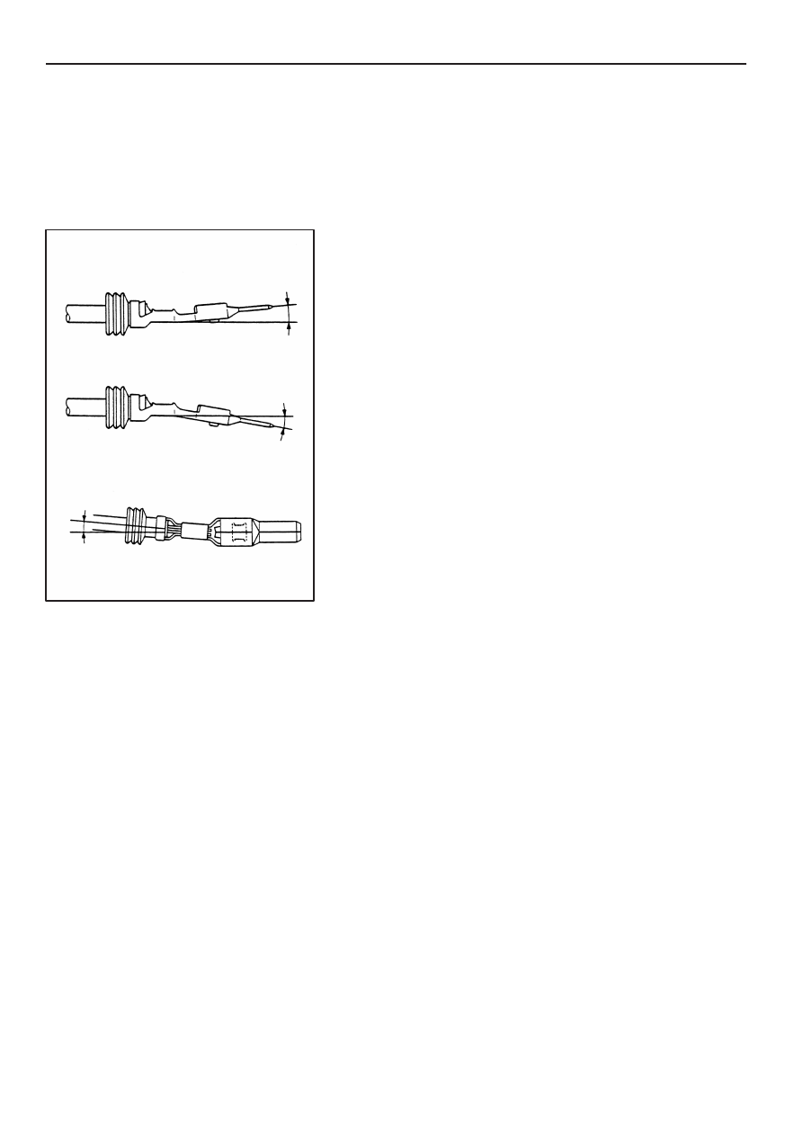
Terminal Deformation

(1)

Terminal Bending in Vertical Direction

(2)

Terminal Bending in Horizontal Direction

1

°

 or less

1

°

 or less

 or less

B–29

TERMINAL AND CONNECTOR REPAIR–TERMINAL REPLACEMENT

45

Wire Harness Repair Manual

(b)

Remove the insulation displacement female terminal

NOTICE:

D

Do not repair the insulation displacement female
terminal.

D

Always replace the part with a new one if any
terminals are removed.

5.

Inspect the terminal and the connector for
damage.

NOTE:

D

The locking clip is easily damaged.

D

Do not reuse the damaged part.

Step 3.

Replace the terminal.

Cut

Existing
terminal

New Terminal with lead

82998–12200

Stripped insulation length (A)
approximately 8 to 11 mm

Existing
Harness

Supplied lead
with New Terminal

A

A

TERMINAL AND CONNECTOR REPAIR–TERMINAL REPLACEMENT

B–30

46

Wire Harness Repair Manual

1.

Cut the Old Terminal from the Harness.

(a)

Use the new wire lead as a guide for proper length.

NOTE: If the length of wire removed is not
approximately the same length as the new piece, the
following problems may develop:

D

Too short –– tension on the terminal, splice, or
the connector, causing and open circuit.

D

Too long –– excessive wire near the connector,
may get pinched or abraded, causing a short
circuit.

HINT:

When connecting a wire harness at there or more

spots to the same connector, cut the wire harness as
shown on the left.

2.

Select the correct replacement terminal with
lead, from the supply parts.

3.

Strip insulation from wire on the harness and
replacement terminal lead.

Start stripping at least 8 mm (0.31 in.) to 11 mm (0.43 in.)
away from the end of the existing harness at vehicle side
and also from the end of the repair wire.

Good Example:

Bad Example:

(Wire insulation is Stripped at a Slant)

(Wire Lead is Cut)

(Insulation Remains on the Lead)

Wire Harness Outside Diameter

Insulation

Calipers

Nominal Size of the Wire

Twist Evenly

Calipers

Wire Lead
Diameter

(When nominal size is 0.3 or more)

B–31

TERMINAL AND CONNECTOR REPAIR–TERMINAL REPLACEMENT

47

Wire Harness Repair Manual

NOTICE:
Take care not to damage the wire when stripping the
wire harness lead. After finishing the operation,
visually inspect the wire. If there is any damage,
perform the operation again.

HINT:
If the wire size is not known, start with largest stripper hole
and work down until a clean strip of the insulation is
removed without nicking or cutting the wire lead.

4.

Select Correct Size of Sleeve from the Supply
Parts.

(a)

Measure the diameter of wire by using the measuring
device as following:

D

When size is based on the outside diameter of the
wire harness
Measure the outside diameter of the wire harness by
placing a measuring device, such as a micrometer or
Vernier Caliper, across the diameter of the insulation on
the lead and taking a reading.

D

When size is based on the nominal size of the wire
lead.
Measure the diameter of the wire lead by placing a
measuring device, such as a micrometer or Vernier
Caliper, across the diameter of the wire lead and taking
a reading.

HINT:
To calculate the ”nominal size” of wire

Nominal size=

3.14 x (Diameter of wire lead)

2

4

Small (Red)

Medium (Blue)

Large (Yellow)

Good Example

Two Stripped Wires

Sleeve (Blue)

Bad Example

Pressure–Contact
Section

Wire in
Short Position

Wire Bend

Special Tool

TERMINAL AND CONNECTOR REPAIR–TERMINAL REPLACEMENT

B–32

48

Wire Harness Repair Manual

(b)

Use the table to determine proper sleeve size

Part Number

Nominal size of wire
(Outside Diameter of
wire)

Small

82999–12010

0.3 or less
(1.0 – 0.2 mm)

Medium

82999–12020

0.5 – 1.25
(2.0 – 1.0 mm)

Large

82999–12030

2 or more
(5.0 – 3.0 mm)

NOTE: For details, refer to sleeve size table on item
4 of STEP 1

5.

Crimp the Replacement Terminal Lead to the
Harness Lead.

(a–1) When nominal size is 0.3 or more

Overlap the two stripped wire ends inside the sleeve
as illustrated on the left.

HINT:

You might find it easier if you use a miniature

special tool as a guide as you insert wires into the sleeve.

B–33

TERMINAL AND CONNECTOR REPAIR–TERMINAL REPLACEMENT

49

Wire Harness Repair Manual

(a–2) When nominal size is less than 0.3.

D

Two stripped wire ends are arranged for the same as
illustrated on the left.

D

Twist the two stripped wire ends together.

D

Insert the twisted wire ends into the sleeve.

Sleeve

Color Marks

Crimping
Tool

”CLOSE HERE”

Contact

”INS” Position

10 mm (0.39 in.)

Three or More Times

TERMINAL AND CONNECTOR REPAIR–TERMINAL REPLACEMENT

B–34

50

Wire Harness Repair Manual

(c)

The crimping tool (AMP Part No. 169060) has color
marks on it. Place the sleeve in the correct section of
the tool according to the color of the sleeve itself.

HINT:

For the crimping tool, AMP ”Part No. 169060” is

convenient to use.

(d)

With the center of the sleeve correctly placed
between the crimping jaws, squeeze the crimping tool
until either end comes into contact at the section
marked by ”CLOSE HERE”.

HINT:

Check to see that the sleeve and wires are still in

the correct position before closing the crimping tool ends
with steady pressure.

(e)

Pull the joined wires to either end. Make sure that they
are joined firmly by the sleeve.

NOTICE:
If the joined wires come loose the splice is defective,
so replace the sleeve and repeat the procedure.

(f)

Crimp both ends of the sleeve with the crimping tool
at the ”INS” position.

6.

Protect Joined Section

Wrap silicon tape around the joins to protect them from
moisture.

NOTE: This job is required in repairs of the engine
compartment, under the floor and other moisture entry
positions.

Three or More Times

10 mm (0.39 in.)

Tape overlapping

10 mm (0.39 in.)

Two or More Times

Finish

B–35

TERMINAL AND CONNECTOR REPAIR–TERMINAL REPLACEMENT

51

Wire Harness Repair Manual

HINT:

D

Before starting the operation, thoroughly wipe dirt and
grease off the sections to be joined.

D

If the adhesive surfaces of two tapes come in contact
they will stick together and will not come apart, so do
not remove the backing film except when using the
tape.

D

Do not let oil and dust, etc. get on the tape surface.

(a)

Ready about 100 mm (3.94 in.) of silicon tape (Part
No. 08231–00045) and peel off the film.

(b)

Stretch the silicon tape until its width is reduced by
half.

(c)

About 10 mm (0.39 in.) from the end of the sleeve,
wrap the silicon tape around the sleeve three or more
times while stretching the tape.

(d)

Wrap the remaining part of the sleeve with half of the
tape overlapping at each turn.

(e)

Firmly wrap the tape two times or more about 10 mm
(0.39 in.) from the other end of the sleeve, then wrap
the tape back towards the start again and firmly finish
winding the tape around the center of the sleeve.

Special Tool

Locking clip

Special Tool

Terminal Lance

”Insulation Displacement Connector”

Terminal Lance

”0.64 Type”

Special Tool

TERMINAL AND CONNECTOR REPAIR–TERMINAL REPLACEMENT

B–36

52

Wire Harness Repair Manual

Step 4.

Install the terminal into the connector.

HINT:
(a)

Make sure the terminal is positioned correctly.

(b)

Insert the terminal until the locking clip locks firmly.

(c)

Insert the terminal with terminal retainer in the
temporary lock position, if equipped.

NOTE: If reusing a terminal, check that the locking clip is
still in good condition and in the proper position.

(a)

If it is on the terminal and not in the proper position,
use the special tool to gently bend the locking clip
back to the original shape.

(b)

Check that the other parts of the terminal are in their
original shape.

NOTICE:
Do not readjust or reuse the terminal lance of the
insulation displacement connector type terminal.
Always change the wire with the repair wire.

NOTICE:
As for 0.64 type terminal, do not adjust the terminal
lance with the special tool.

Splash Proof Type Connector

NOTICE:

D

Removal of the terminal from housing cavity will
cause damage to rubber plug material (the wire
seal), deteriorating waterproofing performance. Be
sure to replace the housing with a new one.

D

Check the withdrawn terminal for the following if
trying to use it again.

D

It is free of deformation and damage

D

It is free of adherents such as rubber plug
material (wire seal)

D

Replace any deformed terminal.


Content   ..  4  5  6  7   ..