Toyota RM06H0E engine. Manual - part 5


  Index      Manuals     Toyota RM06H0E engine. Repair Manual


Search            


Content   ..  3  4  5  6   ..


Toyota RM06H0E engine. Manual - part 5


Special Tool

Lock

Special Tool

Cover

Special Tool

Raise Up

Special Tool

Special Tool
Insert Mark

Terminal
Retainer

Terminal Retainer

[Retainer at Full Lock Position]

Stopper

[Retainer at Temporary Lock Position]

Terminal
Retainer

B–21

TERMINAL AND CONNECTOR REPAIR–TERMINAL REPLACEMENT

37

Wire Harness Repair Manual

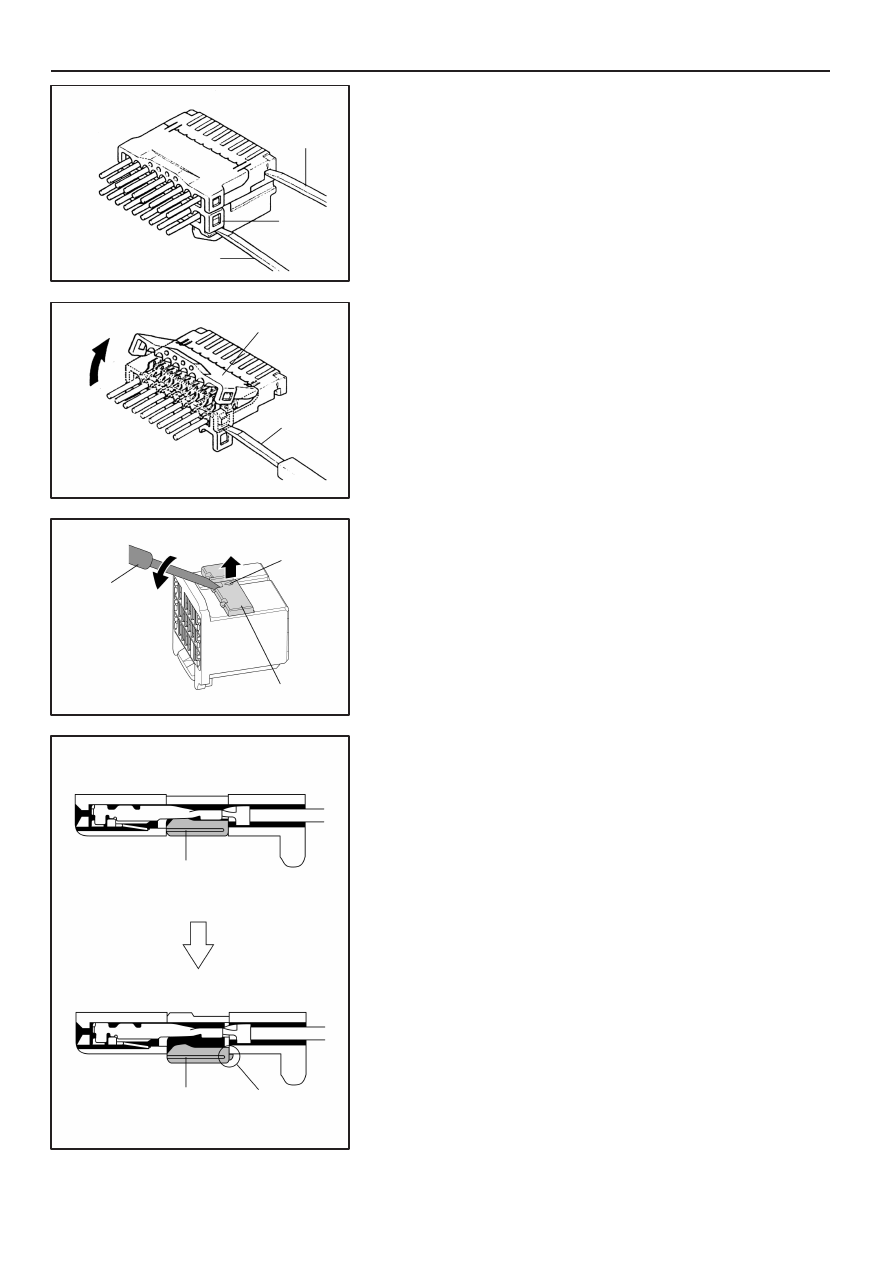
Type K (For Insulation Displacement Connector)

(1)

Separate Connector

Using a special tool, release the lock and separate the
connector into 2.

NOTICE:
Do not apply too muck force to the lock arm.

(2)

w/ Cover : Open Connector Cover

Using a special tool, release the lock and open the cover.

NOTICE:
Do not apply too much force to the lock arm.

Type L (For 0.64 Type Connector)

(1)

Using the special tool, raise the retainer up to the
temporary lock position.

HINT:

The needle insertion position varies according to

the connector’s shape (number of terminals, etc.), so
check the position before inserting it.

Good

Bad

Special Tool

Lock

Special
Tool

Special Tool

Lock

Special Tool

Lock Housing

Upper
Housing

TERMINAL AND CONNECTOR REPAIR–TERMINAL REPLACEMENT

B–22

38

Wire Harness Repair Manual

Type M (For 0.64 of Insulation Displacement Connector
(IDC) Type)

(1)

Remove the Lower Housing

Using a special tool, release the lock and remove the lower
housing.

NOTICE:

D

Do not apply too much force to the lock arm.

D

Mark the upper housing and lower housing to
prevent mistakes when putting them together.

(2)

Remove the Upper Housing

Using a special tool, release the lock and remove the upper
housing from the lock housing.

NOTICE:

D

Do not apply too much force to the lock arm.

D

Mark the upper housing and lower housing to
prevent mistakes when putting them together.

Good

Good

Bad

Bad

Tool Mark

Tool Mark

[Female]

[Male]

B–23

TERMINAL AND CONNECTOR REPAIR–TERMINAL REPLACEMENT

39

Wire Harness Repair Manual

Type N (For 0.64II Type Connector)

(1)

Insert the tool into the insertion position near the tool
mark and raise the terminal retainer up to the
temporary lock position using the tool.

Disengagement order

NOTICE:

D

Use a precision screwdriver (1.2mm) or special tool
when disengaging the terminal retainer.

D

Do not insert the tool into any position other than the
tool insertion positions. After disengaging the
terminal retainer, be sure to check that the terminal
retainer has not been deformed. If it has been
deformed, replace it with a new one.

D

Some connectors have 2 or more tool insertion
positions. When disengaging the terminal retainer
from these types of connectors, follow the
disengagement order shown in the illustration on
the left.

Jig Insertion Hole

TERMINAL AND CONNECTOR REPAIR–TERMINAL REPLACEMENT

B–24

40

Wire Harness Repair Manual

Type O (For 1.0III of KITCUT Type Connector)

(1)

Insert a jig horizontally into the jig insertion hole.

(2)

Push the jig in until it stops.

(3)

Pull out the wire in the direction indicated by the arrow
and remove the housing.

Locking Clip

Pull Out

Connector

Wire Harness

Terminal
Retainer

Locking
Clip

”Waterproof Type”

Special
Tool

B–25

TERMINAL AND CONNECTOR REPAIR–TERMINAL REPLACEMENT

41

Wire Harness Repair Manual

4.

Disconnect Terminal from Connector

(a)

Determine the primary locking system from the
charts.
1. Lock Located on terminal
2. Lock Located on connector
3. Method of entry and operation

(b)

Push the terminal gently into the connector and hold
it in this position.

(c)

Insert the special tool into the connector in the
direction shown in the chart.

(d)

Move the locking clip to the unlock position and hold
it there.

NOTE: Do not apply excessive force to the terminal.
Do not pry on the terminal with the special tool.

(e)

Carefully withdraw the terminal from the connector by
pulling the lead toward the rear of the connector.

NOTE: Do not use too much force. If the terminal
does not come out easily, repeat steps (a) through
(e).

Locking Clip

Terminal Retainer

”Non–Waterproof Type”

SST

Tool Hole

Terminal Lance

Stopper Portion

0.64 Type

Non–waterproof type TLC housing

Insert the tool from wire harness side

TERMINAL AND CONNECTOR REPAIR–TERMINAL REPLACEMENT

B–26

42

Wire Harness Repair Manual

(f)

Insert the SST into the connector in the direction
shown in the chart.

(g)

Insert the SST fully to the tool hole, and push the
terminal lance.

NOTICE:

D

The terminal has a lance shape, therefore, the
housing may be damaged and the terminal may get
stuck if forcibly pried by wires etc.

D

Insert the SST so that the stopper portion surface is
facing up.

(h)

Carefully withdraw the terminal from the connector by
pulling the lead toward the rear of the connector.

NOTICE:
Removal of the terminal from housing cavity will cause
damage to the wire seal section, deteriorating
waterproofing performance. Replace the connector
with a new one.

NOTICE:
Do not insert the special tool into the female terminal
box.  If you do so, replace the terminal with the new one
whether the terminal is broken or not.

NOTICE:
As for Non–waterproof type TLC housing, insert the
special tool into the housing from wire harness side.

Tool Hole

Terminal Lance

Special
Tool

Special
Tool

Tool Hole

Special Tool

Terminal
Lance

Special Tool

0.64 Type

B–27

TERMINAL AND CONNECTOR REPAIR–TERMINAL REPLACEMENT

43

Wire Harness Repair Manual

Insulation Displacement Connector Type

(a)

Using a special tool, push the terminal lance from the
tool hole.

(b)

Carefully withdraw the terminal from the connector by
pulling the lead toward the rear of the connector.

NOTICE:

D

Do not use too much force. If the terminal does not
come out easily, repeat step (a).

D

Always change the wire with the repair wire, in
accordance with step3.

primary
lock

Pull Out Terminal
While Pushing

TERMINAL AND CONNECTOR REPAIR–TERMINAL REPLACEMENT

B–28

44

Wire Harness Repair Manual

1.0III of KITCUT Type Connector

(a)

Remove Female Terminal

(1)

Insert the jig tip at an angle, as shown in the
illustration on the left.

(2)

Move the jig in the direction indicated by the arrow to
push and release the primary lock.

(3)

Pull out the terminal in the direction indicated by the
arrow and detach it.

NOTICE:

D

Do not remove and reinstall the same terminal more
than 3 times.

D

If the terminal is deformed at all, dispose of it.

D

Do not apply too much force when releasing the
primary lock.

D

Do not apply too much force when pulling out the
terminal. If the terminal does not come out easily,
repeat steps (1) to (3).


Content   ..  3  4  5  6   ..