4A–FE engine is an in–line, 4–cylinder, 1.6 liter DOHC 16–valve engine. Manual - part 32


  Index      Manuals     4A–FE engine is an in–line, 4–cylinder, 1.6 liter DOHC 16–valve engine. Repair Manual


Search            


Content   ..  30  31  32  33   ..


4A–FE engine is an in–line, 4–cylinder, 1.6 liter DOHC 16–valve engine. Manual - part 32


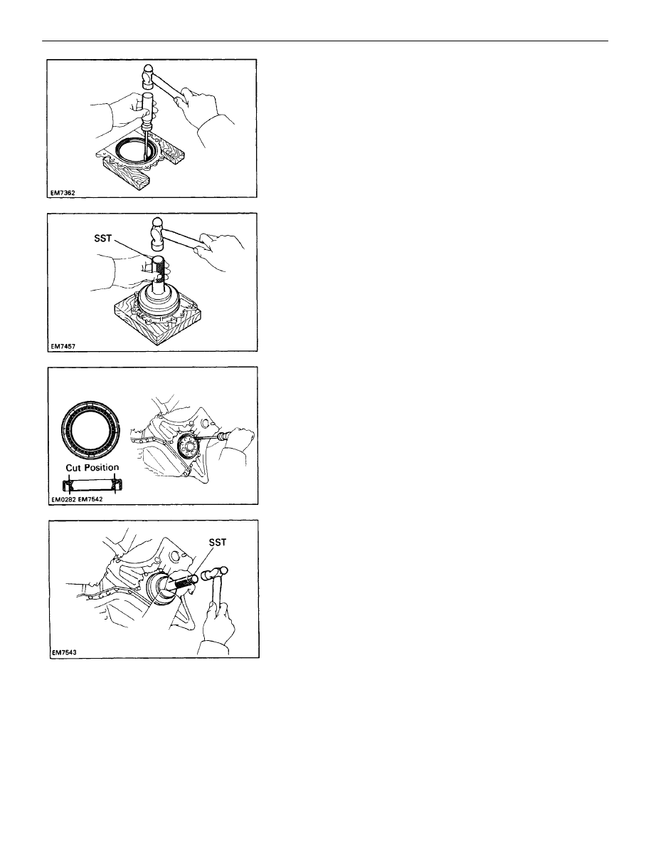
B. If rear oil seal retainer is installed to cylinder block:

(a) Using a knife, cut off the oil seal lip.
(b) Using a screwdriver, pry out the oil seal.
NOTICE: Be careful not to damage the crankshaft.

Tape the screwdriver tip.

(b) Using SST and a hammer, tap in a new oil seal

until its surface is flush with the rear oil seal
edge.

SST 09223–63010
(c) Apply MP grease to the oil seal lip.

(c) Apply M P grease to a new oil seal lip.
(d) Using SST and a hammer, tap in the oil seal until

its surface is flush with the rear oil seal retainer
edge.

SST 09223–63010

2. REPLACE CRANKSHAFT REAR OIL SEAL
A. If rear oil seal retainer is removed from cylinder block:

(a) Using screwdriver and hammer, tap out the oil seal.

ENGINE MECHANICAL

Cylinder Block (3S–GTE)

EM–250

ASSEMBLY OF PISTON AND CONNECTING
ROD ASSEMBLIES
1. ASSEMBLE PISTON AND CONNECTING ROD

(a) Using a small screwdriver, install a new snap ring

on one side of the piston pin hole.

HINT: Be sure that end gap of the snap ring is not
aligned with the pin hole cutout portion of the piston.

(e) Using a small screwdriver, install a new snap ring

on the other side of the piston pin hole.

HINT: Be sure that end gap of the snap ring is not
aligned with the pin hole cutout portion of the pis-
ton.

2. INSTALL PISTON RINGS

(a) Install the oil ring expander and two side rails by

hand.

(c) Coat the piston pin with engine oil.
(d) Align the front marks of the piston and connecting

rod, and push in the piston pin with your thumb.

(b) Gradually heat the piston to 80 – 90

°

C (176 –

194

°

F).

ENGINE MECHANICAL

Cylinder Block (3S–GTE)

EM–251

3. INSTALL BEARINGS

(a) Align the bearing claw with the groove of the connect-

ing rod or connecting cap.

(b) Install the bearings in the connecting rod and connect-

ing rod cap.

(c) Position the piston rings so that the ring ends are

as shown.

NOTICE: Do not align the ring ends.

(b) Using a piston ring expander, install the two com-

pression rings with the code mark facing up-
ward.

Code mark: R

ENGINE MECHANICAL

Cylinder Block (3S–GTE)

EM–252

ASSEMBLY OF CYLINDER BLOCK

(See page 

EM–223

)

HINT:

Thoroughly clean all parts to be assembled.

Before installing the parts, apply new engine oil to all
sliding and rotating surfaces.

Replace all gaskets, O–rings and oil seals with new
parts.

1. INSTALL OIL NOZZLES (See page 

LU–31

)

2. INSTALL MAIN BEARINGS

HINT:

Main bearings come in widths of 19.2 mm (0.756 in.)
and 23.0 mm (0.906 in.). Install the 23.0 mm (0.906
in.) bearings in the No.3 cylinder block journal position
with the main bearing cap. Install the 19.2 mm
(0.756 in.) bearings in the other positions.

Upper bearings have an oil groove and oil holes; lower
bearings do not.

(b) Align the bearing claw with the claw groove of the

main bearing cap, and push in the five lower
bearings.

HINT: A number is marked on each main bearing
cap to indicate the installation position.

3. INSTALL UPPER THRUST WASHERS

Install the two thrust washers under the No.3 journal
position of the cylinder block with the oil grooves facing
outward.

(a) Align the bearing claw with the claw groove of the

cylinder block, and push in the five upper bear-
ings.

ENGINE MECHANICAL

Cylinder Block (3S–GTE)

EM–253

(c) Apply a light coat of engine oil on the threads and

under the heads of the main bearing caps.

(d) Install and uniformly tighten the ten bolts of the

main bearing caps in several passes in the se-
quence
shown.

Torque: 59 N–m (600 kgf–cm, 43 ft–lbf)

(e) Check that the crankshaft turns smoothly.
(f) Check the crankshaft thrust clearance.

(See step 5 on page 

EM–236

)

5. INSTALL MAIN BEARING CAPS AND LOWER THRUST

WASHERS
(a) Install the two thrust washers on the No.3 bearing

cap with the grooves facing outward.

6. INSTALL PISTON AND CONNECTING ROD

ASSEMBLIES
(a) Cover the connecting rod bolts with a short piece of

hose to protect the crankshaft from damage.

(b) Install the five main bearing caps in their proper

locations.

HINT: Each bearing cap has a number and front
mark.

4. PLACE CRANKSHAFT ON CYLINDER BLOCK

ENGINE MECHANICAL

Cylinder Block (3S–GTE)

EM–254

(c) Apply a light coat of engine oil on the threads and

under the cap nuts.

(d) Using SST, install and alternately tighten the cap

nuts in several passes.

Torque: 67 N–m (680 kgf–cm, 49 ft–lbf)

(e) Check that the crankshaft turns smoothly.
(f) Check the connecting rod thrust clearance.

(See step 2 on page 

EM–234

)

7. INSTALL CONNECTING ROD CAPS

(a) Match the numbered connecting rod cap with the

connecting rod.

(b) Install the connecting rod cap with the front mark

facing forward.

(b) Using a piston ring compressor, push the correctly

numbered piston and connecting rod assemblies
into each cylinder with the front mark of the piston
facing forward.

8. INSTALL REAR OIL SEAL RETAINER

Install a new gasket and the retainer with the six bolts.
Torque: 9.3 N–m (95 kgf–cm, 82 in–lbf)

ENGINE MECHANICAL

Cylinder Block (3S–GTE)

EM–255

2. INSTALL OIL COOLER (See pages 

LU–26

 and 27)

3. INSTALL OIL FILTER (See page 

LU–7

)

4. INSTALL OIL PUMP AND OIL PAN

(See pages 

LU–21

 to 23)

5. INSTALL WATER PUMP AND IDLER PULLEY

BRACKET (See pages 

CO–14

 and 15)

6. INSTALL CYLINDER HEAD

(See pages 

EM–140

 to 148)

7. INSTALL TURBOCHARGER (See pages 

TC–15

 to 17)

8. INSTALL PULLEYS AND TIMING BELT

(See pages 

EM–55

 to 60)

9. INSTALL RH ENGINE MOUNTING BRACKET

Install the mounting bracket with the three bolts.
Torque: 52 N–m (530 kgf–cm, 38 ft–lbf)

10. INSTALL PS PUMP BRACKET

Install the PS pump bracket with the three bolts.
Torque: 43 N–m (440 kgf–cm, 32 ft–lbf)

11. REMOVE ENGINE STAND

POST ASSEMBLY

1. INSTALL KNOCK SENSOR

Using SST, install the knock sensor.
SST 09816–30010
Torque: 44 N–m (450 kgf–cm, 33 ft–lbf)

12. INSTALL REAR END PLATE

Torque: 9.3 N–m 195 kgf–cm, 82 in–lbf)

ENGINE MECHANICAL

Cylinder Block (3S–GTE)

EM–256

13. INSTALL FLYWHEEL

(a) Apply adhesive to two or three threads of the

mounting bolt end.

Adhesive: Part No. 08833–00070, THREE BOND 1324

or equivalent

(b) Install the flywheel on the crankshaft.
(c) Install and uniformly tighten the mounting bolts in

several passes in the sequence shown.

Torque: 108 N–m (1,100 kgf–cm, 80 ft–lbf)

14. INSTALL CLUTCH DISC AND COVER

(See CL section)

ENGINE MECHANICAL

Cylinder Block (3S–GTE)

EM–257


Content   ..  30  31  32  33   ..