Toyota Automatic Transmission A340 Series. Repair Manual - part 7
AT1636
AT8225
AT8236
AT8334
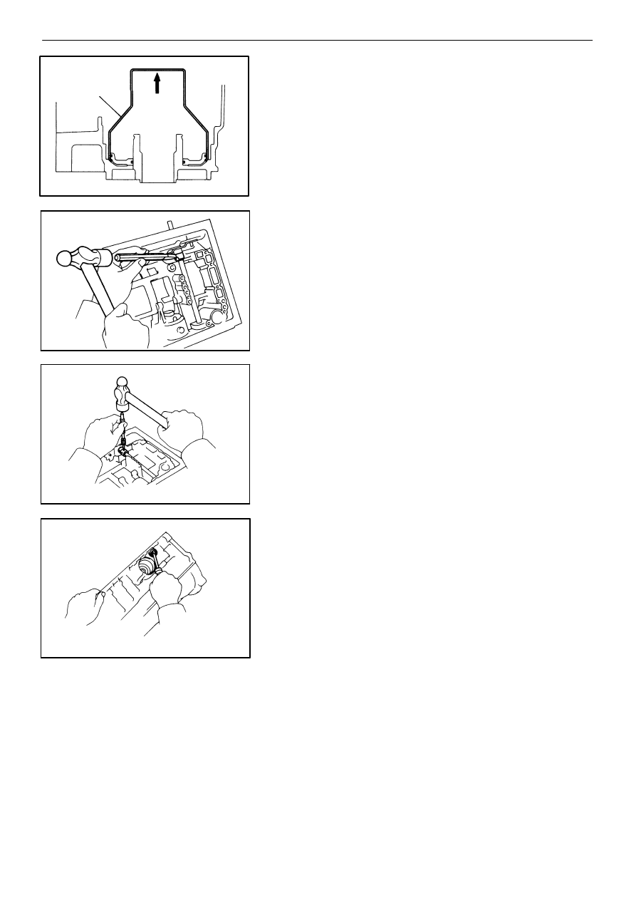
SST
(i)
Insert SST behind No. 1 brake piston and gradu-
ally lift it out of the transmission case.
SST
09350−30020 (09350−07090)
(j)
Remove the two O−rings from No. 1 piston.
40. REMOVE MANUAL VALVE LEVER, SHAFT AND OIL
SEALS
(a)
Using a chisel, cut off the spacer and remove it
from the shaft.
(b)
Using a pin punch, drive out the pin.
(c)
Pull the manual valve lever shaft out through the
case and remove the lever.
(d)
Using a screwdriver, remove the two oil seals.
AT−45
−
AUTOMATIC TRANSMISSION (A340E)
Removal of Component Parts