Toyota Automatic Transmission A340 Series. Repair Manual - part 5


  Index      Toyota     Toyota Automatic Transmission A340 Series. Repair Manual


Search            copyright infringement  


Content   ..  3  4  5  6   ..


Toyota Automatic Transmission A340 Series. Repair Manual - part 5


AT4505

AT5072

AT2310

(SUPRA, CRESSIDA)

AT4836 AT4994

Floor Shift

Column Shift

AT4625

(TRUCK, 4 RUNNER)

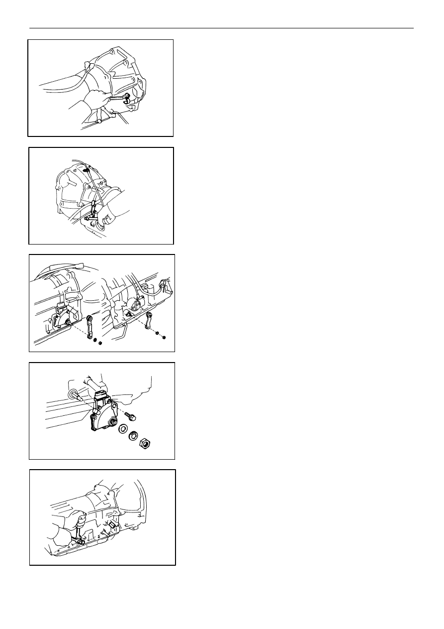
SEPARATE BASIC SUBASSEMBLY

1.

REMOVE WIRE HARNESS CLAMP AND THROTTLE

CABLE CLAMP

2.

REMOVE TRANSMISSION CONTROL SHAFT LEVER

3.

REMOVE NEUTRAL START SWITCH
(a)

Unstake the lock washer.

(b)

Remove the nut and bolt, and then remove the

neutral start switch.

(c)

Remove the lock washer and grommet.

4.

REMOVE UNIONS
(a)

Remove the two unions.

(b)

Remove the O−rings from both unions.

AT−29

AUTOMATIC TRANSMISSION (A340E)

Removal of Component Parts

AT7939

(TRUCK, 4 RUNNER)

AT6647

(SUPRA, CRESSIDA)

AT8216

AT1981 C4141

AT1986

5.

REMOVE SPEEDOMETER DRIVEN GEAR
(a)

Remove the bolt and lock plate.

(b)

Pull out the sleeve.

(c)

Pull out the driven gear from the sleeve.

(d)

Remove the O−ring from the sleeve.

6.

REMOVE SPEED SENSOR
(a)

Disconnect the connector.

(b)

Remove the speed sensor.

(c)

Remove the O−ring from it.

7.

REMOVE TRANSMISSION HOUSING
(a)

Remove the six bolts.

(b)

Remove the transmission housing.

8.

REMOVE EXTENSION HOUSING
(a)

Remove the six bolts.

(b)

Remove the extension housing.

AT−30

AUTOMATIC TRANSMISSION (A340E)

Removal of Component Parts

E7058

AT4637

AT2604 C4151

w/ ABS

w/o ABS

AT3168

SST

AT8217

(c)

Remove the oil apply tube and gasket from the

extension housing.

9.

REMOVE SPEEDOMETER DRIVE GEAR AND BALL
(a)

Using snap ring pliers, remove the snap ring.

(b)

Remove the speedometer drive gear and ball.

10. REMOVE SENSOR ROTOR AND KEY

(a)

Remove the sensor rotor and key.

(b)

Using snap ring pliers, remove the snap ring.

11. REMOVE OIL PAN

NOTICE: Do not turn the transmission over as this will

contaminate the valve body with any foreign matter at

the bottom of the pan.
(a)

Remove the nineteen bolts.

(b)

Install the blade of SST between the transmission

case and oil pan, cut off applied sealer.

SST

09032−00100

NOTICE: Be careful not to damage the oil pan flange.
(c)

Remove the pan by lifting the transmission case.

AT−31

AUTOMATIC TRANSMISSION (A340E)

Removal of Component Parts

AT2630

AT8218

AT1354

AT4440

AT0103

12. EXAMINE PARTICLES IN PAN

Remove the magnets and use them to collect steel

particles. Carefully lock at the foreign matter and par-

ticles in the pan and on the magnets to anticipate the

type of wear you will find in the transmission.

Steel (magnetic)

bearing, gear and clutch 

. . . . . . . 

plate wear

Brass (non−magnetic)

bushing wear

. . 

13. REMOVE OIL STRAINER AND GASKETS

(a)

Remove the three bolts holding the oil strainer to

the valve body.

(b)

Remove the oil strainer and two gaskets.

14. REMOVE OIL TUBES

Pry up both tube ends with a large screwdriver and re-

move the two tubes.

15. REMOVE SOLENOID WIRING

(a)

Disconnect the three connectors from No. 1, No.

2 and lock−up solenoid.

(b)

Remove the stopper plate from the case.

(c)

Pull out the solenoid wiring from the transmission

case.

(d)

Remove the O−ring from the grommet.

AT−32

AUTOMATIC TRANSMISSION (A340E)

Removal of Component Parts

D4992

AT4847

AT5016

SUPRA and CRESSIDA

D4994

AT8339

16. REMOVE VALVE BODY

(a)

Remove the seventeen bolts.

(b)

Disconnect the throttle cable from the cam and

remove the valve body.

17. REMOVE CHECK BALL BODY, ACCUMULATOR

SPRINGS AND PISTONS
(a)

Remove the check ball body and spring.

(b)

Remove the two springs from the C

0

 accumulator

piston.

(c)

Applying compressed air to the oil hole, remove

B

2

 and C

2

 accumulator pistons and two or three

springs.

AT−33

AUTOMATIC TRANSMISSION (A340E)

Removal of Component Parts

AT8220

AT4441

AT8432

AT7874

SST

AT8219

(d)

Applying compressed air to the oil hole, remove

the B

0

 accumulator piston and spring.

(e)

Applying compressed air to the oil hole, remove

the C

0

 accumulator piston.

(f)

Remove the O−ring from each piston.

18. REMOVE THROTTLE CABLE

(a)

Remove the retaining bolt and pull out the throttle

cable.

(b)

Remove the O−ring from the cable.

19. REMOVE OIL PUMP

(a)

Stand up the transmission.

(b)

Remove the seven bolts holding the oil pump to

the transmission case.

(c)

Using SST, remove the oil pump.

SST

09610−20012

(d)

Remove the O−ring from it.

AT−34

AUTOMATIC TRANSMISSION (A340E)

Removal of Component Parts

AT3148

AT8429

AT8428

AT8430

AT8431

(e)

Remove the race from the oil pump.

20. REMOVE OVERDRIVE PLANETARY GEAR UNIT

WITH OVERDRIVE DIRECT CLUTCH AND ONE−WAY

CLUTCH
(a)

Remove the overdrive planetary gear with the

overdrive direct clutch and one−way clutch from

the transmission case.

(b)

Remove the race and assembled bearing and

race.

(c)

Remove the bearing and race.

(d)

Remove the overdrive planetary ring gear from

the transmission case.

AT−35

AUTOMATIC TRANSMISSION (A340E)

Removal of Component Parts

AT8427

D5008

AT4442

Mark

Piston Rod

AT8213

AT8212

SST

21. CHECK PISTON STROKE OF OVERDRIVE BRAKE

(a)

Place SST and a dial indicator onto the overdrive

brake piston as shown in the figure.

SST

09350−30020 (09350−06120)

(b)

Measure the stroke applying and releasing the

compressed air (4 − 8 kg/cm

2

, 57 − 114 psi or

392 − 785 kPa) as shown in the figure.

Piston stroke:

(7M−GTE)

1.75 − 2.05 mm (0.0689 − 0.0807 in.)

(Others)

1.40 − 1.70 mm (0.0551 − 0.0669 in.)

If the values are nonstandard, inspect the discs.

(See page  AT−61)

22. REMOVE FLANGES, PLATES AND DISCS OF

OVERDRIVE BRAKE
(a)

Remove the snap ring.

(b)

Remove the flanges, plates and discs as a set.

(7M−GTE)

Two flanges, four plates and five discs

(Others)

Two flanges, three plates and four discs

The method of inspection, refer to  AT−61.

23. CHECK PISTON ROD STROKE OF SECOND COAST

BRAKE
(a)

Place a mark on the second coast brake piston

rod as shown in the figure.

AT−36

AUTOMATIC TRANSMISSION (A340E)

Removal of Component Parts


Content   ..  3  4  5  6   ..