Toyota FJ Cruiser (GSJ 10, 15 series). Instruction - part 484


  Index      Toyota     Toyota FJ Cruiser (model GSJ 10, 15 series) - service repair instruction 2007 year


Search            copyright infringement  


Content   ..  482  483  484  485   ..


Toyota FJ Cruiser (GSJ 10, 15 series). Instruction - part 484


SS–56

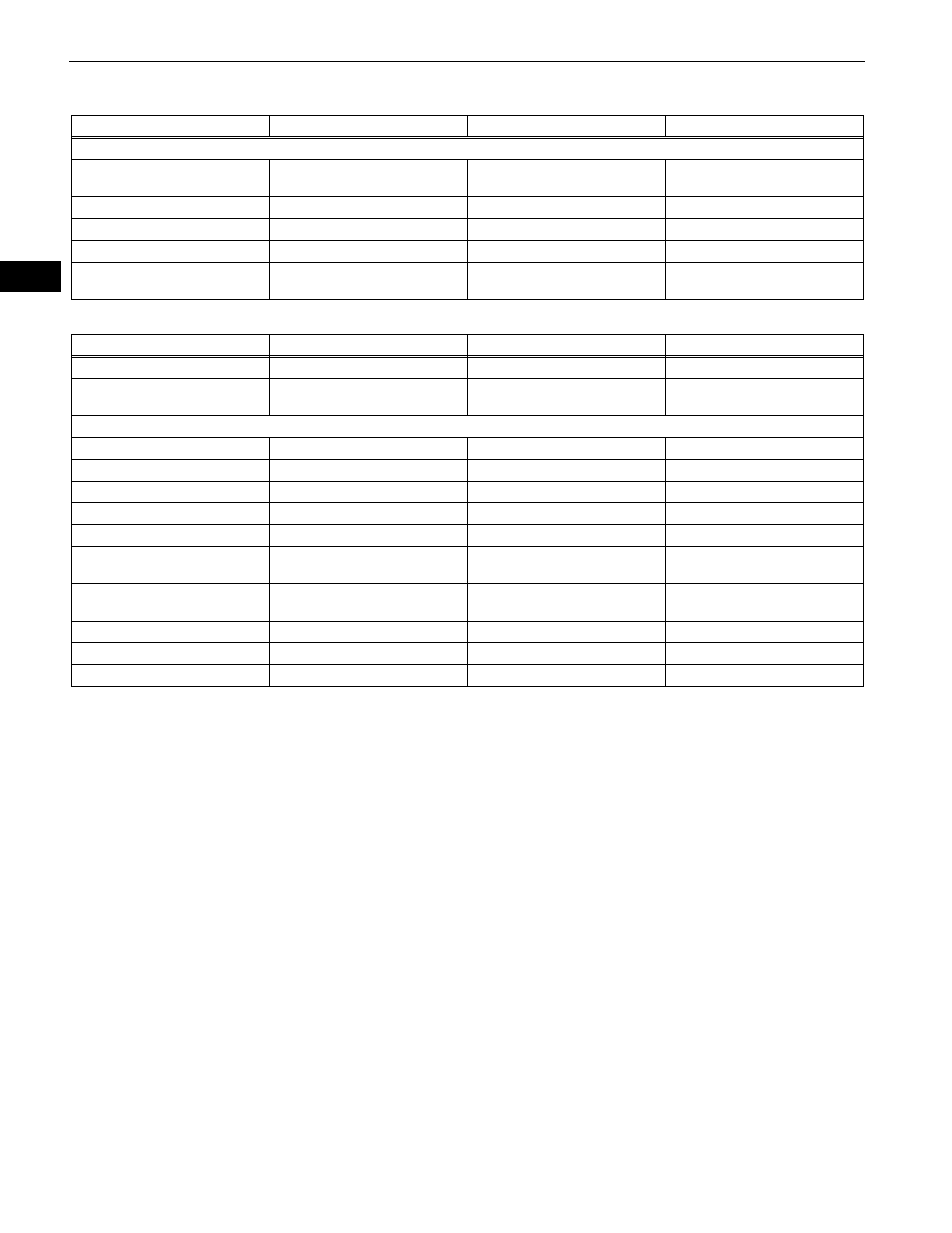
SERVICE SPECIFICATIONS  –  POWER STEERING

SS

TORQUE SPECIFICATIONS

( ): For use without SST

( ): For use without SST

Part tightened

N*m

kgf*cm

ft.*lbf

Power steering vane pump

Vane pump housing rear x Vane 
pump housing front

22

224

16

Pressure port union

69

704

51

Suction port union set bolt

9.0

92

80 in.*lbf

Vane pump assembly x Engine

21

214

15

Pressure feed tube assembly x 
Vane pump assembly

44 (42)

449 (428)

33 (31)

Part tightened

N*m

kgf*cm

ft.*lbf

No. 1 Engine under cover Body

29

296

21

Rear Engine under cove x Body 
for 4WD

29

296

21

Power steering link assembly

Control valve housing set bolt

18

184

13

Rack guide spring cap lock nut

69 (65)

700 (660)

51 (48)

Power steering rack x Rack end

103 (98)

1,050 (1,000)

76 (72)

Tie rod assembly lock nut

88

897

65

Turn pressure tube union nut

25 (23)

250 (235)

18 (17)

Power steering link assembly set 
bolt and nut

100

1,020

74

Pressure feed and return tubes x 
Control valve housing

25 (23)

250 (235)

18 (17)

Pressure feed tube clamp set bolt

28

286

21

Outlet return tube

44 (42)

499 (428)

33 (31)

Tie rod end x steering knuckle

49

500

36

SS–56

SERVICE SPECIFICATIONS  –  AIR CONDITIONING

SS

AIR CONDITIONING

SERVICE DATA

Refrigerant charge volume

570 to 630 g (20.11 to 22.22 oz.)

Magnetic clutch clearance

0.35 to 0.60 mm (0.014 to 0.024 in.)

Magnetic clutch relay

3 - 5 : 10k

Ω or higher

3 - 5 : Below 1

Ω(Apply battery voltage to terminals 1 and 2)

Heater blower relay

3 - 4 : Below 1

3 - 4 : 10k

Ω or higher (Apply battery voltage to terminals 1 and 2)

3 - 5 : 10k

Ω or higher

3 - 5 : Below 1

Ω(Apply battery voltage to terminals 1 and 2)

SERVICE SPECIFICATIONS  –  AIR CONDITIONING

SS–57

SS

TORQUE SPECIFICATIONS

AIR CONDITIONING UNIT

COMPRESSOR AND MAGNETIC CLUTCH

CONDENSER

Part Tightened

N*m

kgf*cm

ft.*lbf

Negative battery terminal x Battery

3.9

40

35 in.*lbf

Part Tightened

N*m

kgf*cm

ft.*lbf

No. 1 cooler evaporator x Cooler expansion valve x Air conditioning tube

3.5

36

31 in.*lbf

Air conditioning unit assembly x Instrument panel reinforcement

9.8

100

87 in.*lbf

Air conditioning unit assembly x Body

5.4

55

48 in.*lbf

Main body ECU (Driver side junction block x Instrument panel reinforcement

8.4

86

74 in.*lbf

Bracket x Main body ECU (Driver side junction block

8.4

86

74 in.*lbf

Steering intermediate shaft assembly x Thrust stopper

36

367

27

Part Tightened

N*m

kgf*cm

ft.*lbf

Magnet clutch hub x Cooler compressor assembly

18

184

13

Pressure relief valve x Cooler compressor assembly

8.0

82

71 in.*lbf

Cooler compressor assembly x Compressor bracket

24.5

250

18

Discharge hose sub-assembly x Cooler compressor assembly

9.8

100

87 in.*lbf

Suction hose sub-assembly x Cooler compressor assembly

9.8

100

87 in.*lbf

Suction hose sub-assembly x Timing chain cover

7.8

80

69

Battery hold down clamp x Battery

6.0

61

53 in.*lbf

Part Tightened

N*m

kgf*cm

ft.*lbf

Cap x Modulator

2.9

30

25 in.*lbf

No. 1 cooler condenser cushion x Body

5.5

56

49 in.*lbf

Cooler condenser assembly x No. 1 cooler condenser cushion

5.5

56

49 in.*lbf

No. 2 cooler condenser cushion RH x Air conditioning tube assembly

5.4

55

48 in.*lbf

No. 2 cooler condenser cushion RH x Cooler condenser assembly

5.5

56

49 in.*lbf

No. 2 cooler condenser cushion LH x Cooler condenser assembly

5.5

56

49 in.*lbf

Cooler bracket x No. 2 cooler condenser cushion LH

5.4

55

48 in.*lbf

Air conditioning tube assembly x Cooler condenser assembly

5.4

55

48 in.*lbf

Discharge hose sub-assembly x Condenser assembly

5.4

55

48 in.*lbf

SERVICE SPECIFICATIONS  –  SUPPLEMENTAL RESTRAINT SYSTEM

SS–57

SS

SUPPLEMENTAL RESTRAINT 
SYSTEM

TORQUE SPECIFICATIONS

Part Tightened

N*m

kgf*cm

ft.*lbf

Steering pad x Steering wheel assembly

8.8

90

78 in.*lbf

Steering wheel assembly x Steering column assembly

50

510

37

Front passenger airbag assembly x Instrument panel reinforcement

20

204

15

Curtain shield airbag assembly x Body

9.8

100

7

Center airbag sensor assembly x Body

17.5

179

13

Front airbag sensor x Body

9.0

92

80 in.*lbf

Side airbag sensor x Body

9.0

92

80 in.*lbf

Rear airbag sensor x Body

9.0

92

80 in.*lbf

Seat position sensor x Front seat assembly

8.0

82

71 in.*lbf


Content   ..  482  483  484  485   ..