Toyota FJ Cruiser (GSJ 10, 15 series). Instruction - part 365


  Index      Toyota     Toyota FJ Cruiser (model GSJ 10, 15 series) - service repair instruction 2007 year


Search            copyright infringement  


Content   ..  363  364  365  366   ..


Toyota FJ Cruiser (GSJ 10, 15 series). Instruction - part 365


POWER STEERING  –  VANE PUMP

PS–11

PS

3.

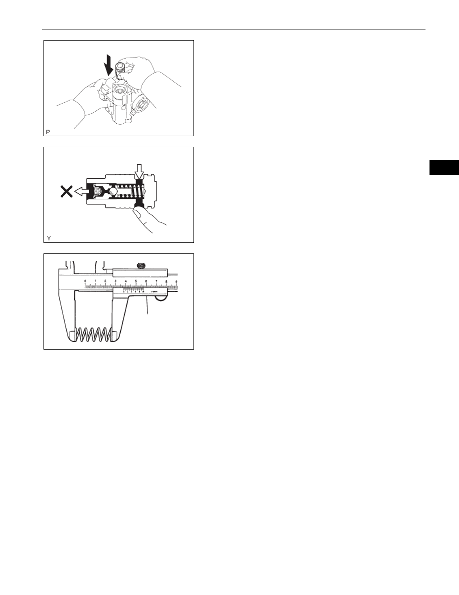
INSPECT FLOW CONTROL VALVE
(a) Coat the flow control valve with power steering fluid 

and check that it falls smoothly into the flow control 
valve hole under its own weight.

(b) Check the flow control valve for leakage. Close one 

of the holes and apply compressed air of 392 to 490 

kPa (4 to 5 kgf/cm

2

, 57 to 71 psi) to the hole on the 

opposite side. Confirm that the air does not flow out 
from the end holes.
If necessary, replace the vane pump assembly.

4.

INSPECT COMPRESSION SPRING
(a) Using vernier calipers, measure the free length of 

the spring.
Minimum free length:

29.2 mm (1.150 in.)

If it is not within the specification, replace the vane 
pump assembly.

5.

INSPECT PRESSURE PORT UNION SUB-ASSEMBLY
(a) If the union seat in the pressure port union is badly 

damaged, it could cause fluid leakage, so replace 
the vane pump assembly.

F051270

Compressed Air

F052069E02

Vernier Caliper

R008702E02

PS–12

POWER STEERING  –  VANE PUMP

PS

REASSEMBLY

NOTICE:
When installing, coat the parts indicated by the arrows 
with power steering fluid (See page 

PS-3

).

1.

INSTALL VANE PUMP HOUSING OIL SEAL
(a) Coat a new vane pump housing oil seal lip with 

power steering fluid.

(b) Using SST and a press, install a new oil seal.

SST

09950-60010 (09951-00280), 09950-70010 
(09951-07100)

NOTICE:
Make sure that the oil seal is installed facing in 
the correct direction.

2.

INSTALL PULLEY SHAFT SUB-ASSEMBLY
(a) Coat the bushing inner surface of the vane pump 

housing front with power steering fluid.

(b) Gradually insert the vane pump shaft.

NOTICE:
Do not damage the vane pump housing oil seal 
lip in the vane pump housing front.

3.

INSTALL VANE PUMP FRONT SIDE PLATE
(a) Coat a new O-ring with power steering fluid and 

install it onto the vane pump housing front.

(b) Coat a new O-ring with power steering fluid and 

install it onto the side plate.

SST

Oil Seal

F051271E01

Power Steering Fluid

F051272E01

F051267

C065368

POWER STEERING  –  VANE PUMP

PS–13

PS

(c) Align the dent of the side plate with that of the vane 

pump housing front and install the side plate.
NOTICE:
Make sure that the side plate is installed facing 
the correct direction.

4.

INSTALL VANE PUMP CAM RING
(a) Align the dent of the cam ring with that of the side 

plate and install the cam ring with the inscribed 
mark facing outward.

5.

INSTALL VANE PUMP ROTOR
(a) Install the vane pump rotor with the inscribed mark 

facing outward.

(b) Coat the 10 vane plates with power steering fluid.
(c) Install the vane plates with the round ends facing 

outward.

(d) Using a snap ring expander, install a new snap ring 

onto the pulley shaft.

6.

INSTALL VANE PUMP REAR HOUSING
(a) Coat a new O-ring with power steering fluid and 

install it onto the vane pump housing rear.

(b) Align the straight pin of the vane pump housing rear 

with the dents of the cam ring, side plate and vane 
pump housing front, and install the vane pump 
housing rear with the 4 bolts.
Torque: 22 N*m (224 kgf*cm, 16 ft.*lbf)

7.

INSPECT PRELOAD
(a) Check that the pump rotates smoothly without 

making any abnormal noises.

(b) Provisionally install the service bolt.

Recommended service bolt:

Thread diameter:

10 mm (0.3937 in.)

Thread pitch:

1.25 mm (0.0492 in.)

Bolt length:

50 mm (1.9685 in.)

F051273

Inscribed Mark

F051274E01

Inscribed Mark

Round End

F051275E02

F051276

C053369

PS–14

POWER STEERING  –  VANE PUMP

PS

(c) Using a torque wrench, check the pump rotating 

torque.
Torque: 0.27 N*m (2.8 kgf*cm, 2.4 in.*lbf)

8.

INSTALL POWER STEERING OIL PRESSURE 
SWITCH
(a) Coat the O-ring with power steering fluid and install 

it onto the power steering oil pressure switch.

(b) Install the power steering oil pressure switch onto 

the vane pump.
Torque: 21 N*m (214 kgf*cm, 15 ft.*lbf)

9.

INSTALL FLOW CONTROL VALVE
(a) Coat the compression spring and flow control valve 

with power steering fluid.

(b) Install the compression spring and flow control 

valve.

(c) Coat a new O-ring with power steering fluid and 

install it onto the pressure port union.

(d) Install the pressure port union.

Torque: 69 N*m (704 kgf*cm, 51 ft.*lbf)

10. INSTALL POWER STEERING SUCTION PORT UNION

(a) Coat a new O-ring with power steering fluid, and 

install it onto the suction port union.

(b) Install the suction port union with the bolt.

Torque: 12 N*m (122 kgf*cm, 9 ft.*lbf)

INSTALLATION

1.

INSTALL VANE PUMP
(a) Install the vane pump assembly with the 2 bolts.

Torque: 43 N*m (438 kgf*cm, 32 ft.*lbf)

(b) Install the wire harness clamp bracket with the bolt.

Torque: 8.0 N*m (82 kgf*cm, 71 in.*lbf)

(c) Connect the oil pressure switch connector.

NOTICE:
Make sure that no oil adheres to the connector.

F051277

F051260

C133829E01


Content   ..  363  364  365  366   ..