Toyota FJ Cruiser (GSJ 10, 15 series). Instruction - part 329


  Index      Toyota     Toyota FJ Cruiser (model GSJ 10, 15 series) - service repair instruction 2007 year


Search            copyright infringement  


Content   ..  327  328  329  330   ..


Toyota FJ Cruiser (GSJ 10, 15 series). Instruction - part 329


ME–48

METER  –  METER / GAUGE SYSTEM

ME

DESCRIPTION

The combination meter assembly controls the fuel receiver gauge in accordance with the resistance of the 
fuel sender gauge that varies depending on the fuel remaining amount in the fuel tank.
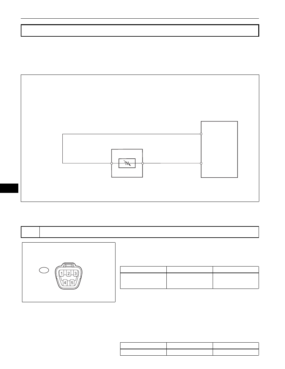
WIRING DIAGRAM

INSPECTION PROCEDURE

(a) Disconnect the L5 fuel sender gauge assembly 

connector.

(b) Check the meter indicator conditions.
Standard

HINT:
This inspection creates an intentional short circuit between 
the connector terminals, to check the meter indicator 
operation.
NOTICE:
Perform the check quickly (within less than 10 seconds).
(c) Measure the voltage.

Standard Voltage

Fuel Gauge Malfunction

1

INSPECT HARNESS AND CONNECTOR

Combination Meter Assembly

Fuel Sender Gauge Assembly

L

E3

E126871E01

Wire Harness Side:

Front View

L5

Fuel Sender Gauge Assembly Connector

E126865E01

Tester Connection

Condition

Specified Condition

L5-2 - L5-3

Short circuit (Ignition 

switch ON)

Fuel gauge indicates 

"F" or more 

(Combination meter)

Tester Connection

Condition

Specified Condition

L5-2 - Body ground

Ignition switch ON

4 to 7V

METER  –  METER / GAUGE SYSTEM

ME–49

ME

(d) Reconnect the fuel sender gauge assembly connector.

NG

OK

(a) Remove the fuel sender gauge assembly.

(b) Check that the float position is between E and F.
(c) Measure the resistance between terminals 2 and 3 of the 

fuel sender gauge connector.
Standard resistance

(d) Reinstall the fuel sender gauge assembly.

NG

OK

REPAIR OR REPLACE HARNESS OR 
CONNECTOR

2

INSPECT FUEL SENDER GAUGE ASSEMBLY

F

E

Warning

1/2

Fuel Sender Gauge Assembly:

E126882E01

Wire Harness Side:

Front View

L5

Fuel Sender Gauge Assembly Connector

E126865E01

Float Level

Float Position (mm (in.))

Specified Condition

F

77.3 (3.04) to 79.3 (3.12)

14.7 

 to 15.3 

1/2

1.6 (0.05)

212.5 

Warning

34.8 (1.37)

375.4 

E

75.0 (2.95) to 77.0 (3.03)

405 

 to 415 

REPLACE FUEL SENDER GAUGE 
ASSEMBLY

ME–50

METER  –  METER / GAUGE SYSTEM

ME

(a) Disconnect the E13 combination meter assembly 

connector.

(b) Disconnect the L5 fuel sender gauge assembly 

connector.

(c) Measure the resistance.

Standard resistance

(d) Reconnect the combination meter assembly and fuel 

sender gauge assembly connectors.

NG

OK

3

CHECK WIRE HARNESS AND CONNECTOR (COMBINATION METER ASSEMBLY - FUEL 
SENDER GAUGE ASSEMBLY)


L

Wire Harness Side:

Combination Meter Assembly Connector

Fuel Sender Gauge Assembly Connector

E13

L5

Front View

E3

Front View

E126866E01

Tester Connection

Specified Condition

E13-16 (L) - L5-2

Below 1

E13-5 (E3) - L5-3

Below 1

E13-16 (L) or L5-2 - Body ground

10k

 or higher

E13-5 (E3) or L5-3 - Body ground

10k

 or higher

REPAIR OR REPLACE HARNESS OR 
CONNECTOR

REPLACE COMBINATION METER ASSEMBLY

METER  –  METER / GAUGE SYSTEM

ME–51

ME

DESCRIPTION

The combination meter assembly controls the engine coolant temperature gauge in accordance with 
engine coolant temperature signals from the ECM.

WIRING DIAGRAM

INSPECTION PROCEDURE

(a) Connect the intelligent tester to the DLC3.
(b) Turn the ignition switch ON and turn the tester ON.
(c) Select the item below from the Data List, and read the 

value displayed on the intelligent tester.

METER

HINT:

If the value is 0

°C (32°F), the sensor circuit is open.

If the value is 127.5

°C (262°F), the sensor circuit is 

shorted.

OK:

Coolant temperature displayed on the tester is 
between 75

°C (167°F) and 105°C (221°F) after 

warming up.

Malfunction in Water Temperature Warning Light

1

READ VALUE OF INTELLIGENT TESTER (ENGINE COOLANT TEMPERATURE)

Combination Meter Assembly

ECM

THWO

E2

THW

TEMP

Engine Coolant 
Temperature Sensor

E126874E01

Item

Measurement Item/Range

(Display)

Normal Condition

Diagnostic Note

COOLANT TEMP

Engine coolant temperature / 

Min.: 0

°C,Max.: 127.5°C

After warming up: 75 to 105

°

(167 to 221

°F)

-


Content   ..  327  328  329  330   ..