Toyota FJ Cruiser (GSJ 10, 15 series). Instruction - part 326


  Index      Toyota     Toyota FJ Cruiser (model GSJ 10, 15 series) - service repair instruction 2007 year


Search            copyright infringement  


Content   ..  324  325  326  327   ..


Toyota FJ Cruiser (GSJ 10, 15 series). Instruction - part 326


ME–36

METER  –  METER / GAUGE SYSTEM

ME

4.

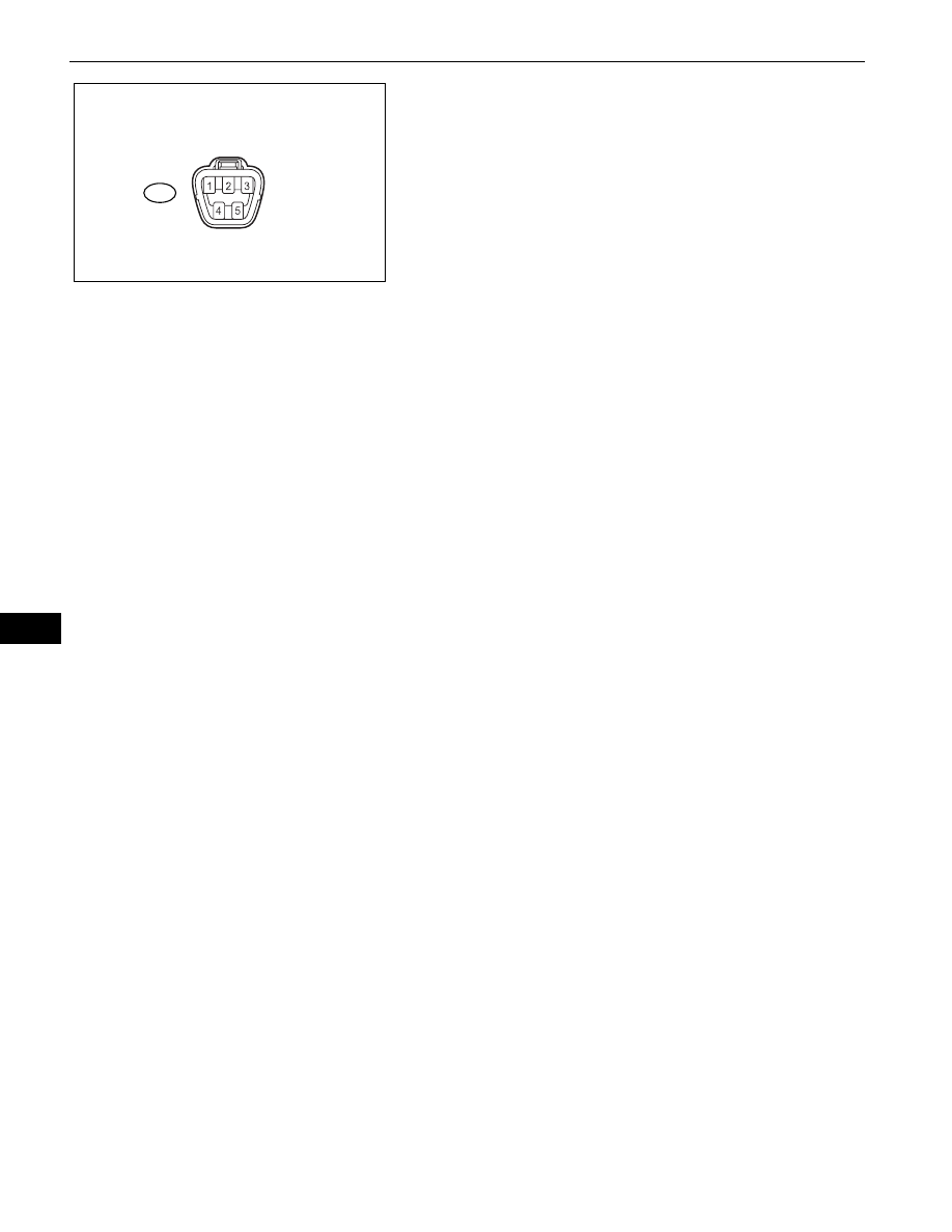
INSPECT FUEL RECEIVER GAUGE
(a) Disconnect the L5 fuel sender gauge connector.
(b) Check the fuel receiver gauge operation when the 

ignition switch is turned to the ON position.
OK:

Needle position is on EMPTY.

(c) Connect terminals 2 and 3 on the wire harness side 

connector of the fuel sender gauge.

(d) Check the fuel receiver gauge operation when the 

ignition switch is turned from OFF to ON.
OK:

Needle position is on FULL.

(e) Reconnect the fuel sender gauge connector.

5.

INSPECT FUEL LEVEL WARNING LIGHT
(a) Disconnect the fuel sender gauge connector.
(b) Turn the ignition switch to the ON position, then 

check that the fuel level needle indicates EMPTY 
and the fuel level warning light comes on.
OK:

Fuel level warning light comes on.

(c) Reconnect the fuel sender gauge connector.

6.

INSPECT ENGINE OIL PRESSURE WARNING LIGHT
(a) Disconnect the engine oil pressure switch 

connector.

(b) Turn the ignition switch to the ON position.
(c) Ground the terminal of the wire harness side 

connector, then check the engine oil pressure 
warning light.
OK:

Engine oil pressure warning light illuminates.

(d) Reconnect the engine oil pressure switch connector.

7.

INSPECT BRAKE WARNING LIGHT
(a) Inspect the parking brake warning light.

(1) Disconnect the parking brake switch connector.
(2) Turn the ignition switch to the ON position.
(3) Ground the terminal of the wire harness side 

connector, then check the parking brake 
warning light.
OK:

Brake warning light illuminates.

(4) Reconnect the parking brake switch connector.

(b) Inspect the brake fluid level warning light.

(1) Disconnect the brake fluid level warning switch 

connector.

(2) Turn the ignition switch to the ON position.
(3) Connect a terminal to the other terminal of the 

wire harness side connector, then check the 
brake fluid level warning switch.
OK:

Brake warning light illuminates.

(4) Reconnect the brake fluid level warning switch 

connector.

Wire Harness Side:

Front View

Fuel Sender Gauge Connector

L5

E126857E01

METER  –  METER / GAUGE SYSTEM

ME–37

ME

8.

INSPECT BRAKE FLUID LEVEL WARNING SWITCH
(a) Remove the reservoir tank cap and strainer.
(b) Disconnect the brake fluid level warning switch 

connector.

(c) Measure the resistance between the terminals.

Standard resistance:

Float inside reservoir tank is in high position 
(switch OFF): 10 k 

 or higher

(d) Use a syphon or a similar tool to drain fluid out of 

the reservoir tank.

(e) Measure the resistance between the terminals.

Standard resistance:

Float inside reservoir tank is in low position 
(switch ON): Below 1 

(f)

Pour the fluid back into the reservoir tank.

(g) Reconnect the brake fluid level warning switch 

connector.

(h) Reinstall the reservoir tank cap and strainer.

9.

OIL MAINTENANCE INDICATOR RESETTING 
PROCEDURE (U.S.A. only)

(a) Set the window display located inside the 

combination meter to the Trip A indication.

(b) Turn the ignition switch OFF.
(c) While pressing the ODO/TRIP display change 

switch (reset switch) (for at least 5 seconds), turn 
the ignition switch ON.

(d) When the reset procedure has been completed 

successfully, the MAINT REQD indicator light turns 
off and the ODO/TRIP meter indicates 0 (zero) and 
then returns to its regular display.
HINT:
If the reset fails, the MAINT REQD indicator light 
remains illuminated. Perform the procedure again.

Oil Maintenance Indicator

Condition

Specified State

Blinks

Vehicle has run 4,500 miles since previous 
setting

Indicator blinks for 15 seconds after ignition 
switch is turned ON (including 3 seconds for 
valve check)

Illuminates

Vehicle has run 5,000 miles since previous 
setting

Indicator illuminates after ignition switch is 
turned ON.

ME–38

METER  –  METER / GAUGE SYSTEM

ME

DESCRIPTION

This circuit provides power to the combination meter assembly.

WIRING DIAGRAM

Entire Combination Meter does not Operate

ES

B

IG+

Combination Meter Assembly

GAUGE

Ignition Switch

AM2

Battery

DOME

Short Pin

E126859E01

METER  –  METER / GAUGE SYSTEM

ME–39

ME

INSPECTION PROCEDURE

(a) Remove the DOME fuse from engine room relay block 

No. 2.

(b) Remove the GAUGE fuse from the main body ECU.
(c) Measure the resistance.

Standard Resistance:

Below 1

(d) Reinstall the fuse.

NG

OK

(a) Disconnect the E13 combination meter connector.
(b) Measure the resistance.

Standard resistance

(c) Measure the voltage.

Standard voltage

1

CHECK FUSE (DOME, GAUGE)

Engine Room R/B No.2:

DOME

GAUGE

Main Body ECU:

E126883E01

CHECK SHORT CIRCUIT IN COMPONENTS 
AND WIRES CONNECTED TO FUSE

2

INSPECT COMBINATION METER ASSEMBLY


Wire Harness Side:

E13

Combination Meter Assembly Connector

Front View

ES

IG+

B

E126858E01

Terminal No.

Condition

Specified Condition

E13-21 (ES) - Body 

ground

Always

Below 1 

Terminal No.

Condition

Specified Condition

E13-2 (IG+) - Body 

ground

Ignition switch ON

11 to 14V


Content   ..  324  325  326  327   ..