Toyota FJ Cruiser (GSJ 10, 15 series). Instruction - part 224


  Index      Toyota     Toyota FJ Cruiser (model GSJ 10, 15 series) - service repair instruction 2007 year


Search            copyright infringement  


Content   ..  222  223  224  225   ..


Toyota FJ Cruiser (GSJ 10, 15 series). Instruction - part 224


FU–12

1GR-FE FUEL  –  FUEL INJECTOR

FU

9.

REMOVE NO. 2 SURGE TANK STAY
(a) Remove the 2 bolts and the No. 2 surge tank stay.

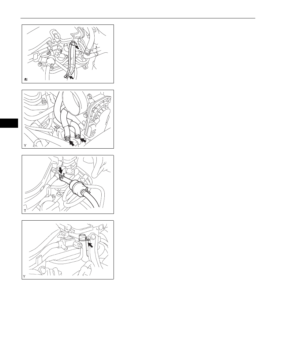
10. REMOVE INTAKE AIR SURGE TANK

(a) Disconnect the 2 water by-pass hoses.

(b) Disconnect the fuel vapor feed hose.

(c) Disconnect the ventilation hose.

A126391

A126395

A126449

A075645

1GR-FE FUEL  –  FUEL INJECTOR

FU–13

FU

(d) Disconnect the 2 VSV connectors.
(e) Disconnect the throttle body with motor connector.
(f)

Separate the 3 wire harness clamps and the hose 
clamp.

(g) Remove the 2 nuts.
(h) Using a socket hexagon wrench 8, remove the 4 

bolts, intake air surge tank and the gasket.

11. DISCONNECT NO. 1 FUEL PIPE SUB-ASSEMBLY

(a) Remove the No. 2 fuel pipe clamp.
(b) Pinch the tube connector, and then pull the fuel pipe 

out of the delivery pipe as shown in the illustration.
NOTICE:

Remove any dirt and foreign objects from the 
fuel tube connector before performing this 
work.

Do not allow any scratches or foreign objects 
on the parts when disconnecting, as the fuel 
tube connector has the O-ring that seals the 
pipe.

Perform this work by hand. Do not use any 
tools.

Do not forcibly bend, twist or turn the nylon 
tube.

Protect the disconnected part by covering it 
with a vinyl bag after disconnecting the fuel 
tube.

If the fuel tube connector and pipe are stuck, 
push and pull to release them.

A075646E01

A075648

Nylon Tube

Tube Connector

O-ring

Pipe

1

2

Pinch

Pull

1 Pinch

A121823E01

FU–14

1GR-FE FUEL  –  FUEL INJECTOR

FU

12. DISCONNECT NO. 2 FUEL PIPE SUB-ASSEMBLY

(a) Remove the No. 2 fuel pipe clamp.
(b) Pinch the tube connector, and then pull the fuel pipe 

out of the delivery pipe as shown in the illustration.
NOTICE:

Remove any dirt and foreign objects from the 
fuel tube connector before performing this 
work.

Do not allow any scratches or foreign objects 
on the parts when disconnecting, as the fuel 
tube connector has the O-ring that seals the 
pipe.

Perform this work by hand. Do not use any 
tools.

Do not forcibly bend, twist or turn the nylon 
tube.

Protect the disconnected part by covering it 
with a vinyl bag after disconnecting the fuel 
tube.

If the fuel tube connector and pipe are stuck, 
push and pull to release them.

13. REMOVE FUEL DELIVERY PIPE SUB-ASSEMBLY

(a) Disconnect the 6 fuel injector connectors.
(b) Remove the 6 bolts and remove the fuel delivery 

pipe together with the 6 fuel injectors.
NOTICE:
Do not drop the injectors when removing the 
fuel delivery pipe.

14. REMOVE FUEL INJECTOR

(a) Pull the 6 injectors out of the delivery pipe.

INSPECTION

1.

INSPECT FUEL INJECTOR ASSEMBLY
(a) Check the resistance.

(1) Using an ohmmeter, measure the resistance 

between the terminals.
Standard resistance

Nylon Tube

Tube Connector

O-ring

Pipe

1

2

Pinch

Pull

A121824E01

A075652E01

Injector

Delivery Pipe

A075653E05

Ohmmeter

A095332E03

Tester Connection

Specified Condition

1 -2

11.6 to 12.4 

at 20°C (68°F)

1GR-FE FUEL  –  FUEL INJECTOR

FU–15

FU

If the result is not as specified, replace the fuel 
injector.

(b) Check the injection volume.

NOTICE:

Perform the test in a well-ventilated area 
away from naked for flames.

Handle the fuel tube connector carefully.

(1) Install the fuel tube connector into SST (hose), 

then connect the tube connector to the fuel 
pipe.
SST

09268-31011 (95336-08070, 09268-
41500)

CAUTION:
Connect the fuel tube connector (quick 
type) after observing the precautions.

(2) Remove the fuel pressure regulator (See page 

FU-22

).

(3) Install the O-ring onto the fuel inlet of the 

pressure regulator.

(4) Connect SST (hose) to the fuel inlet of the 

pressure regulator with another SST (union) 
and the 2 bolts.
SST

09268-31011 (09268-41091, 95336-
08070)

Torque: 9.0 N*m (92 kgf*cm, 80 in.*lbf)

(5) Connect the fuel return hose to the fuel outlet of 

the pressure regulator.

(6) Install a new O-ring onto the injector.
(7) Connect SST (adaptor and hose) to the injector 

and hold the injector and union with SST 
(clamp).
SST

09268-31011 (95336-08070, 09268-
41100), 09268-41140

(8) Set the injector in a graduated cylinder.

CAUTION:
Install a suitable vinyl tube onto the injector 
to prevent gasoline splashes.

SST

SST

SST

Injector

Fuel Tube 
Connector

Pressure 
Regulator

A075912E01

Fuel Tube Connector

SST (Hose)

(SST)

B012947E08

SST 
(Hose)

SST 
(Union)

Fuel Return Hose

Pressure 
Regulator

A076630E01

SST

SST        
(Adapter)

O-Ring

Vinyl Tube

SST 
(Clamp)

A075914E03


Content   ..  222  223  224  225   ..