Toyota FJ Cruiser (GSJ 10, 15 series). Instruction - part 149


  Index      Toyota     Toyota FJ Cruiser (model GSJ 10, 15 series) - service repair instruction 2007 year


Search            copyright infringement  


Content   ..  147  148  149  150   ..


Toyota FJ Cruiser (GSJ 10, 15 series). Instruction - part 149


1GR-FE ENGINE MECHANICAL  –  TIMING CHAIN

EM–29

EM

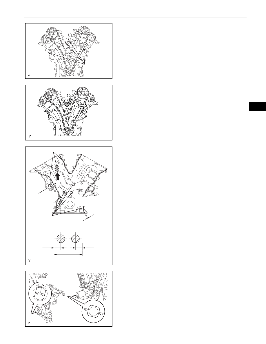
(c) Apply continuous beads of seal packing (diameter 3 

to 4 mm (0.12 to 0.16 in.)) to the 4 locations shown 
in the illustration.
Seal packing:

Toyota Genuine Seal Packing Black, Three 
Bond 1207B or the equivalent

(d) Keep the seal surface between the cylinder block 

and the cylinder head shown in the illustration free 
of oil before installing the chain cover.

(e) Apply continuous beads of seal packing (diameter 3 

to 4 mm (0.12 to 0.16 in.)) to the timing chain cover 
as shown in the illustration.
Seal packing:

Water pump part:

Toyota Genuine Seal Packing 1282B, Three 
Bond 1282B or the equivalent

Other parts:

Toyota Genuine Seal Packing Black, Three 
Bond 1207B or the equivalent

NOTICE:

Install the timing chain cover within 3 minutes 
of applying the seal packing. The timing chain 
cover bolts and nuts must be tightened within 
15 minutes of the installation. Otherwise the 
seal packing must be removed and reapplied.

Do not apply seal packing to portion A shown 
in the illustration.

(f)

Align the key way of the oil pump drive rotor with the 
rectangular portion of the crankshaft timing gear, 
and slide the timing chain cover into place.

Seal Packing

G036306E01

A126368

Seal Packing

Seal Packing

Water Pump 
Part

Water Pump Part

Seal Width 3 to 4 mm

3 to 4 mm

3 to 4 mm

16.7 mm

3 to 4 mm

B - B’

B

B

A

A076303E04

15 q

A076304E01

EM–30

1GR-FE ENGINE MECHANICAL  –  TIMING CHAIN

EM

(g) Install the timing chain cover with the 24 bolts and 2 

nuts. Tighten the bolts and nuts uniformly in several 
steps.
Torque: 23 N*m (235 kgf*cm, 17 ft.*lbf)
NOTICE:
Pay attention not to wrap the chain and slipper 
over the timing chain cover seal line.
Each bolt length is as follows

8.

INSTALL CYLINDER HEAD COVER SUB-ASSEMBLY 
LH (See page 

EM-57

)

9.

INSTALL CYLINDER HEAD COVER SUB-ASSEMBLY 
(See page 

EM-58

)

10. INSTALL WATER INLET (See page 

CO-9

)

11. INSTALL VVT SENSOR (See page 

ES-417

)

12. INSTALL CAMSHAFT TIMING OIL CONTROL VALVE 

ASSEMBLY (See page 

ES-415

)

13. INSTALL IGNITION COIL ASSEMBLY (See page 

IG-8

)

14. INSTALL INTAKE AIR SURGE TANK (See page 

FU-

17

)

15. INSTALL NO. 2 SURGE TANK STAY (See page 

FU-19

)

16. INSTALL NO. 1 SURGE TANK STAY (See page 

FU-19

)

17. INSTALL OIL BAFFLE PLATE (See page 

FU-19

)

18. INSTALL THROTTLE BODY BRACKET (See page 

FU-

19

)

19. INSTALL AIR CLEANER ASSEMBLY (See page 

ES-

431

)

20. INSTALL OIL PAN SUB-ASSEMBLY

(a) Remove any old packing (FIPG) material.

HINT:
Do not drop any oil on the contact surfaces of the 
cylinder block, rear oil seal and oil pan.

(b) Install a new O-ring onto the oil pump.

A

B

B

B

B

B

B

B

B

B

B

B

B

B

B

A

A

A

A

A

A

Nut

Nut

A

A

B

G036303E02

Bolt

Length

A

25 mm (0.98 in.)

B

55 mm (2.17 in.)

A076452E01

1GR-FE ENGINE MECHANICAL  –  TIMING CHAIN

EM–31

EM

(c) Apply a continuous bead of seal packing (diameter 

3 to 4 mm (0.12 to 0.16 in.)) to the oil pan as shown 
in the illustration.
Seal packing:

Toyota Genuine Seal Packing Black, Three 
Bond 1207B or the equivalent

NOTICE:
Install the oil pan within 3 minutes of applying 
the seal packing. Tighten the oil pan bolts and 
nuts within 15 minutes of installing the oil pan. 
Otherwise, the seal packing must be removed 
and reapplied.

(d) Install the oil pan with the 17 bolts and 2 nuts, and 

tighten the bolts and nuts uniformly in several steps.
Torque: 10 mm (0.39 in.) head

10 N*m (102 kgf*cm, 7.4 ft.*lbf)
12 mm (0.47 in.) head
21 N*m (214 kgf*cm, 16 ft.*lbf)
Nut
21 N*m (1,214 kgf*cm, 16 ft.*lbf)

HINT:
Each bolt length is as follows:

(e) Install the 4 housing bolts.

Torque: 37 N*m (377 kgf*cm, 27 ft.*lbf)

(f)

Install the flywheel housing under cover.

21. INSTALL OIL STRAINER SUB-ASSEMBLY

(a) Install a new gasket and the oil strainer with the 2 

nuts.
Torque: 9.0 N*m (92 kgf*cm, 80 in.*lbf)

22. INSTALL NO. 2 OIL PAN SUB-ASSEMBLY

(a) Remove any old packing (FIPG) material.

HINT:
Do not drop any oil on the contact surfaces of the oil 
pan and No. 2 oil pan.

Seal 
Packing

Seal Width: 3 to 4 mm

G036801E01

A

A

A

A

A

A

B

B

B

B

Nut

C

C

Nut

B

B

B

B

B

G036833E01

Bolt

Length

A

25 mm (0.98 in.)

B

45 mm (1.77 in.)

C

14 mm (0.55 in.)

Flywheel Housing 
Under Cover

A076446E01

A072951E01

EM–32

1GR-FE ENGINE MECHANICAL  –  TIMING CHAIN

EM

(b) Apply a continuous bead of seal packing (diameter 

3 to 4 mm (0.12 to 0.16 in.)) as shown in the 
illustration.
Seal packing:

Toyota Genuine Seal Packing Black, Three 
Bond 1207B or the equivalent

NOTICE:
Install the No. 2 oil pan within 3 minutes of 
applying the seal packing. Tighten the No. 2 oil 
pan bolts and nuts within 15 minutes of 
installing the No. 2 oil pan. Otherwise, the seal 
packing must be removed and reapplied.

(c) Install the No. 2 oil pan with the 10 bolts and 2 nuts. 

Tighten the bolts and nuts uniformly in several 
steps.
Torque: Bolt

9.0 N*m (92 kgf*cm, 80 in.*lbf)
Nut
10 N*m (102 kgf*cm, 7.4 in.*lbf)

23. INSTALL CRANKSHAFT PULLEY

(a) Using SST, install the pulley set bolt.

SST

09213-54015 (91651-60855), 09330-00021

Torque: 250 N*m (2,549 kgf*cm, 184 ft.*lbf)

24. INSTALL NO. 1 IDLER PULLEY SUB-ASSEMBLY

(a) Install the idler pulley with the bolt.

Torque: 39 N*m (398 kgf*cm, 29 ft.*lbf)
HINT:
DOUBLE is marked on the No. 1 idler pulley to 
distinguish it from the No. 2 idler pulley.

Seal Packing

Seal Width: 3 to 4 mm

A076308E02

A072949E01

SST

A076309E02

“DOUBLE”

A076438E01


Content   ..  147  148  149  150   ..