Toyota FJ Cruiser (GSJ 10, 15 series). Instruction - part 148


  Index      Toyota     Toyota FJ Cruiser (model GSJ 10, 15 series) - service repair instruction 2007 year


Search            copyright infringement  


Content   ..  146  147  148  149   ..


Toyota FJ Cruiser (GSJ 10, 15 series). Instruction - part 148


1GR-FE ENGINE MECHANICAL  –  TIMING CHAIN

EM–25

EM

21. REMOVE OIL BAFFLE PLATE (See page 

FU-11

)

22. REMOVE NO. 1 SURGE TANK STAY (See page 

FU-11

)

23. REMOVE NO. 2 SURGE TANK STAY (See page 

FU-12

)

24. REMOVE INTAKE AIR SURGE TANK (See page 

FU-

12

)

25. REMOVE IGNITION COIL ASSEMBLY (See page 

IG-8

)

26. REMOVE CAMSHAFT TIMING OIL CONTROL VALVE 

ASSEMBLY (See page 

ES-414

)

27. REMOVE VVT SENSOR (See page 

ES-417

)

28. REMOVE WATER INLET (See page 

CO-8

)

29. REMOVE CYLINDER HEAD COVER SUB-ASSEMBLY 

(See page 

EM-40

)

30. REMOVE CYLINDER HEAD COVER SUB-ASSEMBLY 

LH (See page 

EM-40

)

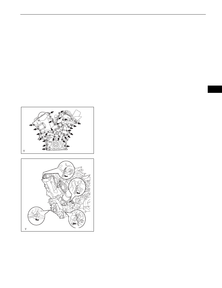
31. REMOVE TIMING CHAIN OR BELT COVER SUB-

ASSEMBLY
(a) Remove the 24 bolts and 2 nuts.

(b) Remove the timing chain cover by prying between 

the timing chain cover, cylinder head or cylinder 
block with a screwdriver.
NOTICE:
Be careful not to damage the contact surfaces of 
the timing chain cover, cylinder block and 
cylinder head.

(c) Remove the O-ring from the LH cylinder head.

32. REMOVE TIMING GEAR CASE OR TIMING CHAIN 

CASE OIL SEAL (See page 

EM-163

)

G036303E01

G036304E01

EM–26

1GR-FE ENGINE MECHANICAL  –  TIMING CHAIN

EM

33. SET NO. 1 COMPRESSION TO TDC/COMPRESSION

(a) Using the crankshaft pulley set bolt, turn the 

crankshaft to align the crankshaft set key with the 
timing line of the cylinder block.

(b) Check that the timing marks of the camshaft timing 

gears are aligned with the timing marks of the 
bearing caps as shown in the illustration.
If not, turn the crankshaft 1 complete revolution 
(360

°) and align the timing marks as above.

34. REMOVE NO. 1 CHAIN TENSIONER ASSEMBLY

NOTICE:

Never rotate the crankshaft with the chain 
tensioner removed.

When rotating the camshaft with the timing chain 
removed, rotate the crankshaft counterclockwise 
40

° from the TDC first.

(a) While turning the stopper plate of the tensioner 

upward, push in the plunger of the chain tensioner 
as shown in the illustration.

(b) While turning the stopper plate of the tensioner 

downward, insert a bar of 

φ 3.5 mm (0.138) into the 

holes in the stopper plate and tensioner to fix the 
stopper plate.

(c) Remove the 2 bolts, then remove the chain 

tensioner.

35. REMOVE CHAIN TENSIONER SLIPPER

36. REMOVE IDLE SPROCKET ASSEMBLY

(a) Using a 10 mm hexagon wrench, remove the No. 2 

idle gear shaft, No. 1 idle gear and No. 1 idle gear 
shaft.

37. REMOVE NO. 2 CHAIN VIBRATION DAMPER

(a) Remove the 2 No. 2 chain vibration dampers.

38. REMOVE CHAIN SUB-ASSEMBLY

Timing Line

Set Key

A076450E02

Bank 1:

Timing Marks

Timing Marks

Timing Marks

Bank 2:

G036290E06

Stopper Plate

Stopper Plate

Push

A072958E02

A072959E01

1GR-FE ENGINE MECHANICAL  –  TIMING CHAIN

EM–27

EM

INSTALLATION

1.

INSTALL CHAIN TENSIONER SLIPPER

2.

INSTALL NO. 1 CHAIN TENSIONER ASSEMBLY
(a) While turning the stopper plate of the tensioner 

clockwise, push in the plunger of the tensioner as 
shown in the illustration.

(b) While turning the stopper plate of the tensioner 

counterclockwise, insert a bar of 

φ 35 mm (0.138 in.) 

into the holes in the stopper plate and tensioner to 
fix the stopper plate.

(c) Install the chain tensioner with the 2 bolts.

Torque: 10 N*m (102 kgf*cm, 7.4 ft.*lbf)

3.

INSTALL CHAIN SUB-ASSEMBLY
(a) Set the No. 1 cylinder to TDC/ compression.

(1) Align the timing marks of the camshaft timing 

gears and bearing caps.

(2) Using the crankshaft pulley set bolt, turn the 

crankshaft to align the crankshaft set key with 
the timing line of the cylinder block.

Stopper Plate

Stopper Plate

Push

A076294E02

Bank 1:

Timing Marks

Timing Marks

Timing Marks

Bank 2:

G036290E06

Timing Line

Set Key

A076296E02

EM–28

1GR-FE ENGINE MECHANICAL  –  TIMING CHAIN

EM

(b) Align the yellow mark link with the timing mark of the 

crankshaft timing link.

(c) Align the orange mark links with the timing marks of 

the camshaft timing gears, and install the chain.

4.

INSTALL NO. 2 CHAIN VIBRATION DAMPER
(a) Install the 2 No. 2 chain vibration dampers.

5.

INSTALL IDLE SPROCKET ASSEMBLY
(a) Apply a light coat of engine oil to rotating surface of 

the No. 1 idle gear shaft.

(b) Temporarily install the No. 1 idle gear shaft together 

with the No. 2 idle gear shaft with the knock pin of 
the No. 1 idle gear shaft and the knock pin groove of 
the cylinder block are aligned.
NOTICE:
Orient the idle gear shafts correctly.

(c) Using a 10 mm hexagon wrench, tighten the No. 2 

idle gear shaft.
Torque: 60 N*m (612 kgf*cm, 44 ft.*lbf)

(d) Remove the bar from the chain tensioner.

6.

INSTALL TIMING GEAR CASE OR TIMING CHAIN 
CASE OIL SEAL (See page 

EM-163

)

7.

INSTALL TIMING CHAIN OR BELT COVER SUB-
ASSEMBLY
(a) Remove any old packing (FIPG) material.

HINT:
Do not drop any oil on the contact surfaces of the 
timing chain cover, cylinder head and cylinder block.

(b) Install a new O-ring onto the bank 2 cylinder head 

as shown in the illustration.

Timing Mark

Mark Link

A076297E03

Mark Links

Timing Marks

G036259E02

Knock Pin

Forward

A076299E02

G036305E01


Content   ..  146  147  148  149   ..