Toyota FJ Cruiser (GSJ 10, 15 series). Instruction - part 125
ES–448
1GR-FE ENGINE CONTROL SYSTEM – ACCELERATOR PEDAL
ES
ENGINE
1GR-FE ENGINE CONTROL SYSTEM
ACCELERATOR PEDAL
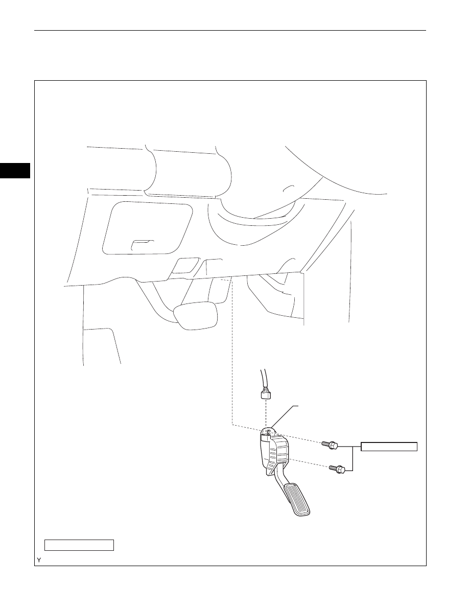
COMPONENTS
ACCELERATOR PEDAL ROD
ASSEMBLY
N*m (kgf*cm, ft*lbf) : Specified torque
5.0 (51, 44 in.*lbf)
A126414E01