Toyota FJ Cruiser (GSJ 10, 15 series). Instruction - part 117
1GR-FE ENGINE CONTROL SYSTEM – VVT SENSOR
ES–417
ES
REMOVAL
1.
DISCONNECT CABLE FROM NEGATIVE BATTERY
TERMINAL
2.
DRAIN ENGINE COOLANT (See page
)
3.
REMOVE V-BANK COVER (See page
)
4.
REMOVE AIR CLEANER ASSEMBLY (See page
)
5.
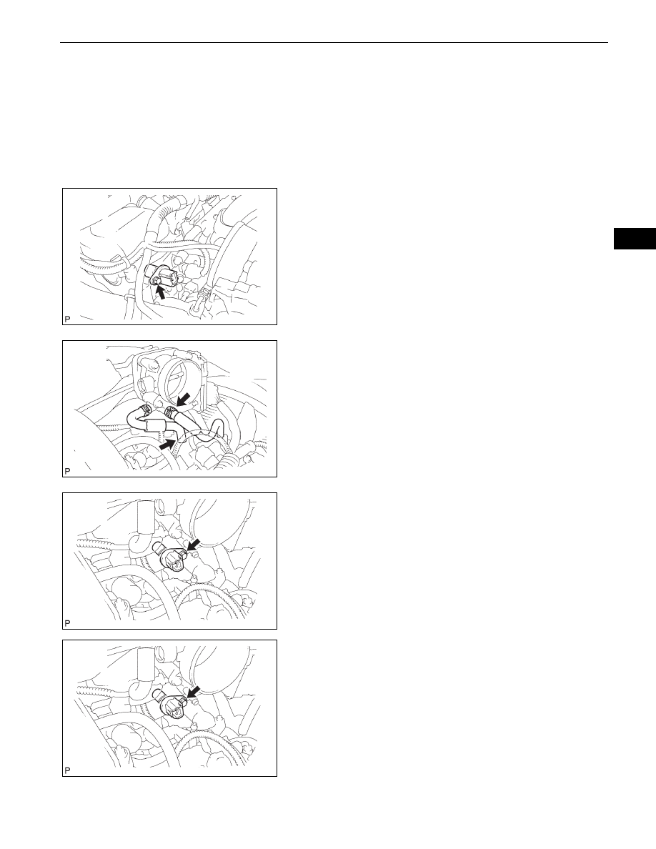
REMOVE VVT SENSOR
(a) Bank 1 side VVT sensor:
(1) Disconnect the VVT sensor connector.
(2) Remove the bolt and VVT sensor.
(b) Bank 2 side VVT sensor:
(1) Disconnect the No. 4 water by-pass hose and
No. 5 water by-pass hose.
(2) Disconnect the VVT sensor connector.
(3) Remove the bolt and VVT sensor.
INSTALLATION
1.
INSTALL VVT SENSOR
(a) Bank 2 side VVT sensor:
(1) Apply a light coat of engine oil to the O-ring of
the VVT sensor.
(2) Install the VVT sensor with the bolt.
Torque: 8.0 N*m (82 kgf*cm, 71 in.*lbf)
Bank 1:
A076413E02
Bank 2:
A076414E02
Bank 2:
A076415E02
Bank 2:
A076415E02