Toyota FJ Cruiser (GSJ 10, 15 series). Instruction - part 109


  Index      Toyota     Toyota FJ Cruiser (model GSJ 10, 15 series) - service repair instruction 2007 year


Search            copyright infringement  


Content   ..  107  108  109  110   ..


Toyota FJ Cruiser (GSJ 10, 15 series). Instruction - part 109


1GR-FE ENGINE CONTROL SYSTEM  –  SFI SYSTEM

ES–391

ES

(a) Remove the IGN fuse from the driver side J/B.
(b) Check the IGN fuse resistance.

Standard Resistance:

Below 1 

(c) Reinstall the IGN fuse.

NG

OK

(a) Disconnect the A1 ignition switch connector.
(b) Check the resistance.

Standard Resistance

(c) Reconnect the ignition switch connector.

NG

OK

(a) Turn the ignition switch ON.
(b) Measure the voltage between the terminals of the B3 

and E47 ECM connectors.
Standard Voltage

NG

4

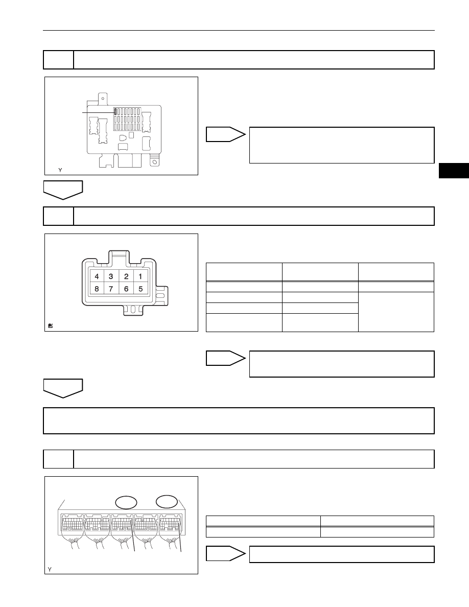
CHECK FUSE (IGN FUSE)

IGN Fuse

Driver Side J/B:

A133441E01

CHECK FOR SHORT IN ALL HARNESSES 
AND CONNECTORS CONNECTED TO FUSE 
AND REPLACE FUSE

5

INSPECT IGNITION OR STARTER SWITCH ASSEMBLY

Component Side:

Ignition Switch

A056879E34

Ignition Switch 

Positions

Tester Connections

Specified Conditions

LOCK

All Terminals

10 k

 or higher

ACC

2 - 4

Below 1 

ON

1 - 2, 1 - 4, 5 - 6

START

1 - 3, 1 - 4, 3 - 4, 5 - 6, 5 - 

7, 6 - 7

REPLACE IGNITION OR STARTER SWITCH 
ASSEMBLY (See page 

ST-19

)

CHECK AND REPLACE HARNESS AND CONNECTOR (BATTERY - IGNITION SWITCH, IGNITION 
SWITCH - ECM)

6

INSPECT ECM (MREL VOLTAGE)

B3

E47

E1 (-)

MREL(+)

ECM Connector

G100798E10

Tester Connections

Specified Conditions

MREL (E47-8) - E1 (B3-1)

11 to 14 V

REPLACE ECM (See page 

ES-446

)

ES–392

1GR-FE ENGINE CONTROL SYSTEM  –  SFI SYSTEM

ES

OK

(a) Remove the EFI fuse from the engine room R/B.
(b) Check the EFI fuse resistance.

Standard Resistance:

Below 1 

(c) Reinstall the EFI fuse.

NG

OK

(a) Remove the EFI relay from the engine room R/B.
(b) Check the EFI relay resistance.

Standard Resistance

(c) Reinstall the EFI relay.

NG

OK

7

CHECK FUSE (EFI FUSE)

EFI Fuse

Engine Room R/B:

A133436E02

CHECK FOR SHORT IN ALL HARNESSES 
AND CONNECTORS CONNECTED TO FUSE 
AND REPLACE FUSE

8

INSPECT EFI RELAY

B016200E02

Tester Connections

Specified Conditions

3 - 5

10 k

 or higher

Below 1 

(when battery voltage applied to terminals 1 and 2)

REPLACE EFI RELAY

1GR-FE ENGINE CONTROL SYSTEM  –  SFI SYSTEM

ES–393

ES

(a) Check the harness and connector between the EFI relay 

and ECM.
(1) Remove the EFI relay from the engine room R/B.
(2) Disconnect the E47 ECM connector.
(3) Check the resistance.

Standard Resistance (Check for open)

Standard Resistance (Check for short)

(4) Reinstall the EFI relay.
(5) Reconnect the ECM connector.

(b) Check the harness and connector between the EFI relay 

and body ground.
(1) Remove the EFI relay from the engine room R/B.
(2) Check the resistance.

Standard Resistance (Check for open)

(3) Reinstall the EFI relay.

NG

OK

9

CHECK HARNESS AND CONNECTOR (EFI RELAY- ECM, EFI RELAY - BODY GROUND)

1

2

5

3

Engine Room R/B:

EFI Relay

ECM Connector

E47

MREL

A133471E01

Tester Connections

Specified Conditions

EFI relay (1) - MREL (E47-8)

Below 1 

Tester Connections

Specified Conditions

EFI relay (1) or MREL (E47-8) - Body ground

10 k

 or higher

Tester Connections

Specified Conditions

EFI relay (2) - Body ground

Below 1 

REPAIR OR REPLACE HARNESS OR 
CONNECTOR

CHECK AND REPAIR HARNESS AND CONNECTOR (TERMINAL +B OF ECM - BATTERY 
POSITIVE TERMINAL)

ES–394

1GR-FE ENGINE CONTROL SYSTEM  –  SFI SYSTEM

ES

DESCRIPTION

The ECM constantly generates 5 V power from the battery voltage supplied to the +B (BATT) terminal to 
operate the microprocessor. The ECM also provides this power to the sensors through the VC output 
circuit.

When the VC circuit is short-circuited, the microprocessor in the ECM and sensors that are supplied 
power through the VC circuit are inactivated because the power is not supplied from the VC circuit. Under 
this condition, the system does not start up and the MIL does not illuminate even if the system 
malfunctions.
HINT:
Under normal conditions, the MIL is illuminated for several seconds when the ignition switch is first turned 
ON. The MIL goes off when the engine is started.

VC Output Circuit

5 V Constant Voltage Circuit

Microprocessor

From EFI Fuse

From EFI Relay

BATT

Throttle Position Sensor, Accelerator 
Pedal Position Sensor, etc. (Sensors 
which have IC)

Engine Coolant Temperature Sensor, 
Intake Air Temperature Sensor, etc.

R

+B

VCTA, VCPA, 
VCP2

ECM

A116143E09


Content   ..  107  108  109  110   ..