Toyota FJ Cruiser (GSJ 10, 15 series). Instruction - part 41
1GR-FE ENGINE CONTROL SYSTEM – SFI SYSTEM
ES–119
ES
DESCRIPTION
Refer to DTC P0115 (See page
MONITOR DESCRIPTION
ECT sensor cold start monitor
When a cold engine start is performed and then the engine is warmed up, if the ECT sensor value does
not change, it is determined that a malfunction has occurred. If this is detected in 2 consecutive driving
cycles, the MIL is illuminated and a DTC is set.
ECT sensor soak monitor
After a warmed up engine is started, if the ECT sensor value does not change when the engine is stopped
and then the next cold engine start is performed, it is determined that a malfunction has occurred. If this is
detected in 2 consecutive driving cycles, the MIL is illuminated and a DTC is set.
MONITOR STRATEGY
TYPICAL ENABLING CONDITIONS
ECT Sensor cold start monitor:
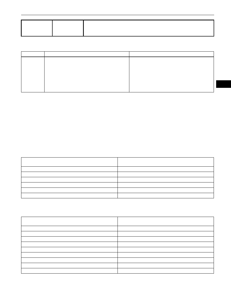
DTC
P0116
Engine Coolant Temperature Circuit Range /
Performance Problem
DTC No.
DTC Detection Conditions
Trouble Areas
P0116
When either of following conditions met (2 trip detection
logic):
•
When cold engine started and engine warmed up, Engine
Coolant Temperature (ECT) sensor value does not
change.
•
After warmed up engine started, if ECT sensor value
does not change when engine stopped and then next
cold engine start performed, it determined that
malfunction has occurred.
•
Thermostat
•
ECT sensor
Related DTCs
P0116: ECT sensor cold start monitor
P0116: ECT sensor soak monitor
Required Sensors/Components (Main)
ECT sensor
Required Sensors/Components (Related)
Intake Air Temperature (IAT) sensor and Mass Air Flow (MAF) meter
Frequency of Operation
Once per driving cycle
Duration
10 seconds
MIL Operation
2 driving cycles
Sequence of Operation
None
Monitor runs whenever following DTCs not present
P0100 to P0103: MAF meter
P0110 to P0113: IAT sensor
Battery voltage
10.5 V or more
Time after engine start
1 second or more
ECT at engine start
Less than 60
°C (140°F)
IAT sensor circuit
OK
Soak time
5 hours or more
Accumulated MAF
900 g or more
Engine
Running
Fuel cut
OFF
Difference between ECT at engine start and IAT
Less than 40
°C (72°F)