Toyota FJ Cruiser (GSJ 10, 15 series). Instruction - part 39


  Index      Toyota     Toyota FJ Cruiser (model GSJ 10, 15 series) - service repair instruction 2007 year


Search            copyright infringement  


Content   ..  37  38  39  40   ..


Toyota FJ Cruiser (GSJ 10, 15 series). Instruction - part 39


1GR-FE ENGINE CONTROL SYSTEM  –  SFI SYSTEM

ES–111

ES

DESCRIPTION

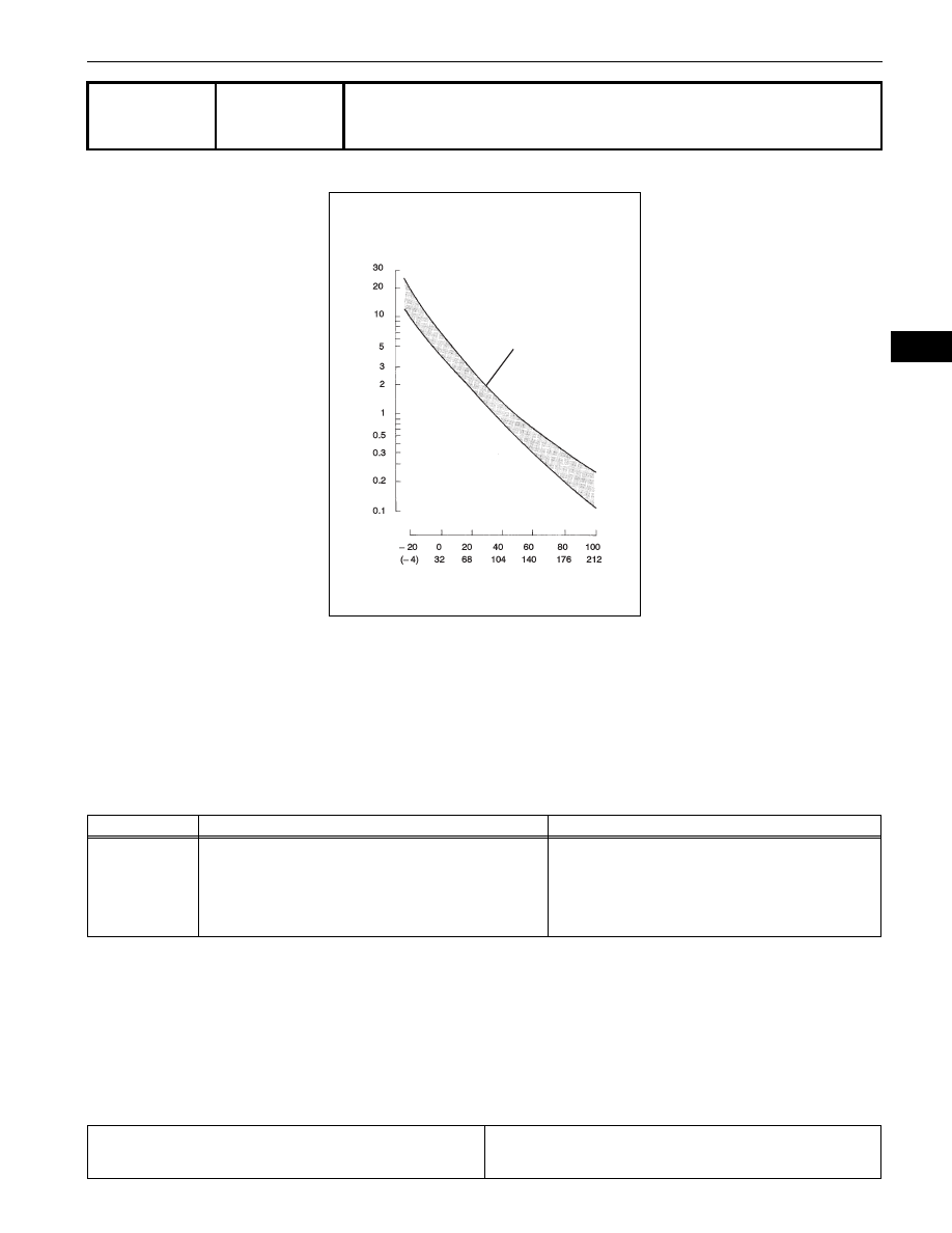
The Intake Air Temperature (IAT) sensor, mounted on the Mass Air Flow (MAF) meter, monitors the IAT. 
The IAT sensor has a built in thermistor with a resistance that varies according to the temperature of the 
intake air. When the IAT is low, the resistance of the thermistor increases. When the temperature is high, 
the resistance drops. These variations in resistance are transmitted to the ECM as voltage changes (See 
Fig. 1). 
The IAT sensor is powered by a 5 V supply from the THA terminal of the ECM, via resistor R.
Resistor R and the IAT sensor are connected in series. When the resistance value of the IAT sensor 
changes, according to changes in the IAT, the voltage at terminal THA also varies. Based on this signal, 
the ECM increases the fuel injection volume when the engine is cold to improve driveability.

MONITOR DESCRIPTION

The ECM performs OBD II monitoring based on the values from the intake air temperature sensor. If there 
is no change of the sensor value within the normal range, the ECM will not be able to perform OBD II 
monitoring or will misdiagnose that there is a malfunction in the sensor. The ECM detects the stuck intake 
air temperature sensor value by performing monitoring after the ignition switch is turned OFF or START.

MONITOR STRATEGY

DTC

P0111

Intake Air Temperature Sensor Gradient Too 
High

DTC No.

DTC Detection Conditions

Trouble Areas

P0111

When either of following conditions met (2 trip detection 
logic):

The intake air temperature rise is large, from the previous 
trip warm-up to the following trip.

When the change in the intake air temperature after 
engine start is less than the threshold value.

Mass air flow meter

Related DTCs

P0111: Intake air temperature sensor rationality (After engine stop)
P0111: Intake air temperature sensor rationality (After cold engine 
start)

Fig. 1

Resistance

Acceptable

Temperature

(kΩ)

(°C)
(°F)

A067628E14

ES–112

1GR-FE ENGINE CONTROL SYSTEM  –  SFI SYSTEM

ES

TYPICAL ENABLING CONDITIONS

All:

After engine stop:

After cold engine start:

TYPICAL MALFUNCTION THRESHOLDS

After engine stop:

After cold engine start:

WIRING DIAGRAM

Refer to DTC P0110 (See page 

ES-102

).

INSPECTION PROCEDURE

(a) Connect the intelligent tester to the DLC3.
(b) Turn the ignition switch ON.
(c) Turn the tester ON.
(d) Enter the following menus: DIAGNOSIS / ENHANCED 

OBD II / DTC INFO / CURRENT CODES.

(e) Read DTCs.

Required Sensors/Components (Main)

Intake Air Temperature (IAT) sensor

Required Sensors/Components (Sub)

Engine Coolant Temperature (ECT) sensor and Mass Air Flow (MAF) 
meter

Frequency of Operation

Once per driving cycle

Duration

10 seconds or more

MIL Operation

2 driving cycles

Sequence of Operation

None

Monitor runs whenever following DTCs are not present

-

Battery voltage

10.5 V or more

Time after engine start

10 seconds or more

ECT sensor circuit

OK

ECT in previous driving cycle

80

°C (176°F) or more

Accumulated MAF amount in previous driving cycle

7,000 g or more

ECT when 30 minutes elapsed after engine stop

20

°C (68°F) or more

Key-off duration

5 hours

Time after engine start

10 seconds or more

ECT sensor circuit

OK

ECT

70

°C (158°F) or more

Accumulated MAF amount

7,000 g or more

One of the following conditions 1 or 2 is met:

-

1. Duration while engine load is low

120 seconds or more

2. Duration while engine load is high

10 seconds or more

IAT change

Less than 1

°C (2°F) 

IAT change

Less than 1

°C (2°F) 

1

CHECK ANY OTHER DTCS OUTPUT (IN ADDITION TO DTC P0111)

1GR-FE ENGINE CONTROL SYSTEM  –  SFI SYSTEM

ES–113

ES

Result

HINT:
If any DTCs other than P0111 are output, troubleshoot 
those DTCs first.

B

A

Display (DTC Output)

Proceed To

P0111 and other DTCs

A

P0111

B

REPLACE MASS AIR FLOW METER (See 
page 

ES-409

)

GO TO DTC CHART (See page 

ES-57

)

ES–114

1GR-FE ENGINE CONTROL SYSTEM  –  SFI SYSTEM

ES

DESCRIPTION

A thermistor is built into the Engine Coolant Temperature (ECT) sensor, of which the resistance value 
varies according to the ECT.
The structure of the sensor and its connection to the ECM are the same as those of the Intake Air 
Temperature (IAT) sensor.
HINT:
When any of DTCs P0115, P0117 and P0118 are set, the ECM enters fail-safe mode. During fail-safe 
mode, the ECT is estimated to be 80

°C (176°F) by the ECM. Fail-safe mode continues until a pass 

condition is detected.

HINT:
When any of these DTCs are set, check the ECT by selecting the following menu items on an intelligent 
tester: DIAGNOSIS / ENHANCED OBD II / DATA LIST / PRIMARY / COOLANT TEMP.

MONITOR DESCRIPTION

The Engine Coolant Temperature (ECT) sensor is used to monitor the ECT. The ECT sensor has a 
thermistor with a resistance that varies according to the temperature of the engine coolant. When the 
coolant temperature is low, the resistance in the thermistor increases. When the temperature is high, the 
resistance drops.
These variations in resistance are reflected in the voltage output from the sensor. The ECM monitors the 
sensor voltage and uses this value to calculate the ECT. When the sensor output voltage deviates from 
the normal operating range, the ECM interprets this as a fault in the ECT sensor and sets a DTC.
Example:
If the sensor voltage output is more than 4.91 V for 0.5 seconds or more, the ECM determines that there 
is an open in the ECT sensor circuit, and sets DTC P0118. Conversely, if the voltage output is less than 
0.14 V for 0.5 seconds or more, the ECM determines that there is a short in the sensor circuit, and sets 
DTC P0117.
If the malfunction is not repaired successfully, a DTC is set 0.5 seconds after the engine is next started.

MONITOR STRATEGY

DTC

P0115

Engine Coolant Temperature Circuit

DTC

P0117

Engine Coolant Temperature Circuit Low Input

DTC

P0118

Engine Coolant Temperature Circuit High Input

DTC No.

Proceed To

DTC Detection Conditions

Trouble Areas

P0115

Step 1

Open or short in Engine Coolant 
Temperature (ECT) sensor circuit for 0.5 
seconds (1 trip detection logic)

Open or short in ECT sensor circuit

ECT sensor

ECM

P0117

Step 4

Short in Engine Coolant Temperature 
(ECT) sensor circuit for 0.5 seconds (1 
trip detection logic)

Short in ECT sensor circuit

ECT sensor

ECM

P0118

Step 2

Open in Engine Coolant Temperature 
(ECT) sensor circuit for 0.5 seconds (1 
trip detection logic)

Open in ECT sensor circuit

ECT sensor

ECM

Temperature Displayed

Malfunctions

-40

°C (-40°F)

Open circuit

140

°C (284°F) or higher

Short circuit

Related DTCs

P0115: Engine coolant temperature sensor open/short (Fluctuating)
P0117: Engine coolant temperature sensor short (Low voltage)
P0118: Engine coolant temperature sensor open (High voltage)


Content   ..  37  38  39  40   ..