Toyota FJ Cruiser (GSJ 10, 15 series). Instruction - part 23
1GR-FE ENGINE CONTROL SYSTEM – SFI SYSTEM
ES–47
ES
CHECK MODE PROCEDURE
HINT:
Intelligent tester only:
Compared to normal mode, check mode is more sensitive to
malfunctions. Therefore, check mode can detect the
malfunctions that cannot be detected by normal mode.
NOTICE:
All the stored DTCs and freeze frame data are erased if:
1) the ECM is changed from normal mode to check mode
or vice versa; or 2) the ignition switch is turned from ON
to ACC or OFF while in check mode.
Before changing modes, always check and make a note
of any DTCs and freeze frame data.
1.
CHECK MODE PROCEDURE (Using an intelligent
tester)
(a) Check and ensure the following conditions:
(1) Battery voltage 11 V or more
(2) Throttle valve fully closed
(3) Transmission in the P or N positions
(4) A/C switched OFF
(b) Turn the ignition switch OFF.
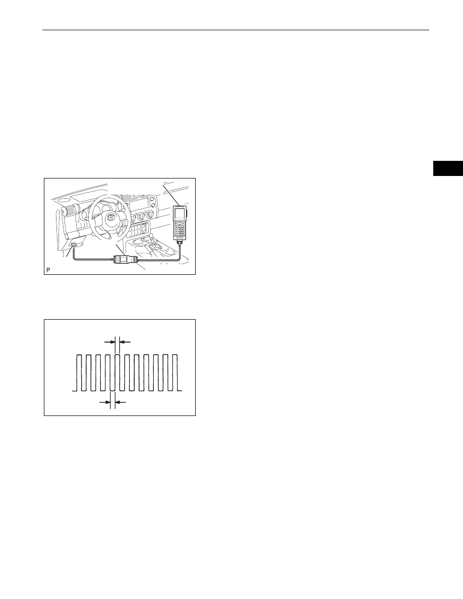
(c) Connect an intelligent tester to the DLC3.
(d) Turn the ignition switch ON.
(e) Turn the tester ON.
(f)
Select the following menu items: DIAGNOSIS /
ENHANCED OBD II / CHECK MODE.
(g) Switch the ECM from normal mode to check mode.
(h) Make sure the MIL flashes as shown in the
illustration.
(i)
Start the engine.
(j)
Make sure the MIL turns off.
(k) Simulate the conditions of the malfunction described
by the customer.
(l)
Check DTCs and freeze frame data using the tester.
Intelligent Tester
DLC3
CAN VIM
H102157E03
0.13 seconds
0.13 seconds
ON
OFF
A076900E12